32-Cavity Injection Mold for a Slim Tubular Part
A production tool for a thin-wall part, built as one matched core and cavity set. This record covers what the drawing asked for, where the build was difficult, and how the steel and the first samples were measured before the tool was released.
- Cavities
- 32Four columns of eight, one block
- Tool steel
- Hardened tool steelGrade fixed in the order
- Cavity work
- ±0.01 mmOn the dimensions marked on the tool drawing
- Verification
- CMM plus trial samplesEvery cavity on the same datum
Customer name, part drawing, resin grade and order volumes stay in the project file. What is published here is the tool, the build sequence and the inspection method.
Project at a glance
The record in one block. Each line was agreed at order and checked before the tool was released.
- Tool type
- Two-plate injection mold, cold runner, one part per cavity
- Cavity count
- 32, arranged four columns by eight rows
- Part
- Slim tubular part, thin wall, long coreWall thickness and length are set by the customer drawing
- Cavity steel
- Hardened tool steel, grade and hardness range fixed in the order
- Cavity tolerance
- ±0.01 mm on the cavity dimensions marked on the tool drawingNot a blanket tolerance for every surface
- Core and cavity
- Machined and measured as a matched pair
- Working surfaces
- Polished in the draw direction, edges protected
- Cooling
- Circuits on both sides, core cooled from the inside
- Guiding
- Four guide pillars into bushed bores in the opposite plate
- Handling
- Lifting eyes on both plates
- Trial
- T0 for first shots, T1 for measured samples from each cavity
- Handover
- Tool drawing, steel certificate, hardness record, T1 report, process sheet
The part, and what it asks of the tool
A thin wall moves the difficulty from the outside of the block to the inside of it.
The part is a slim tube with a thin wall and a closed profile. Most of the machining time on a tool like this goes into the core, not into the plate. The plate carries the outline; the core decides the wall.
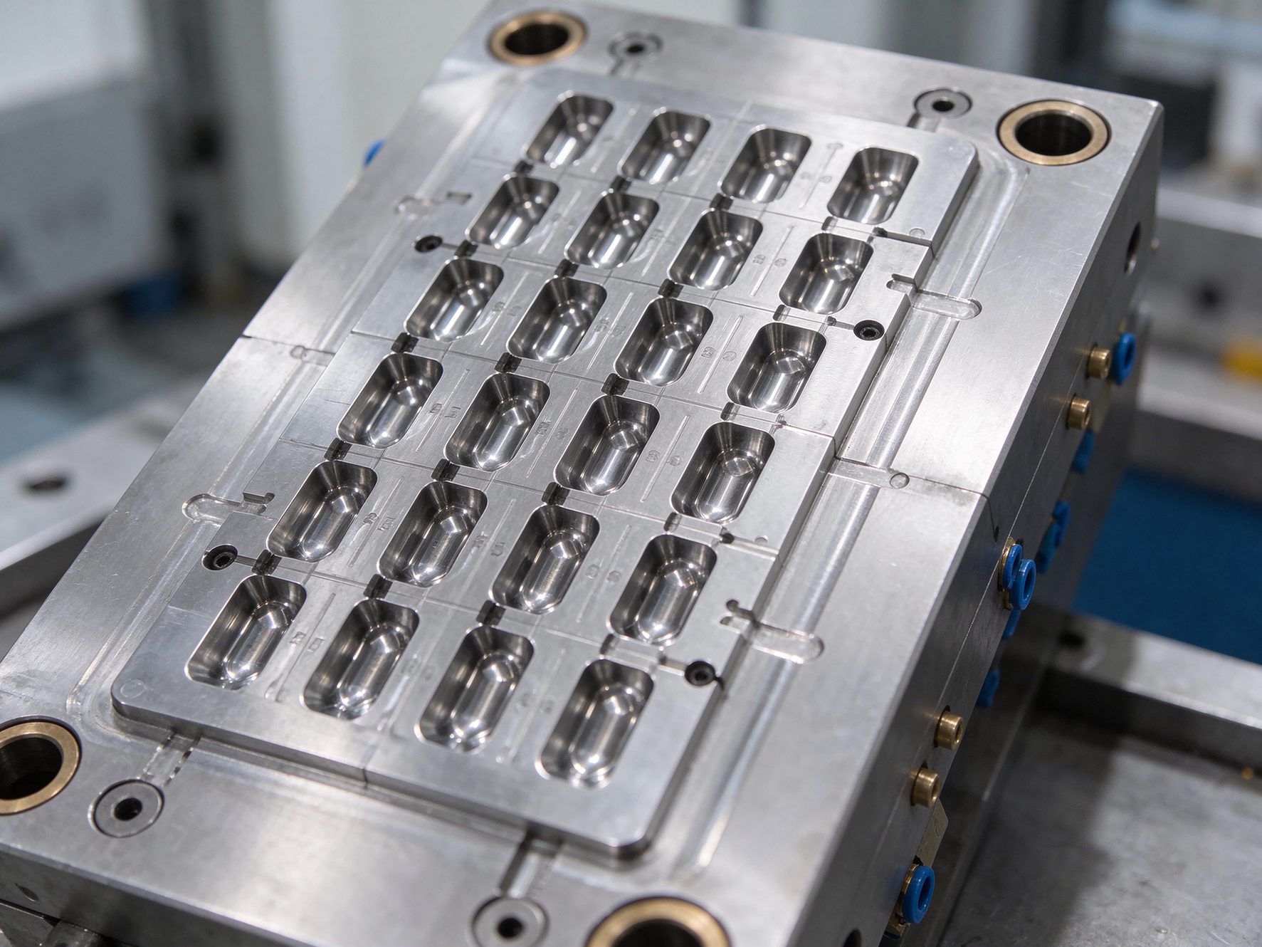
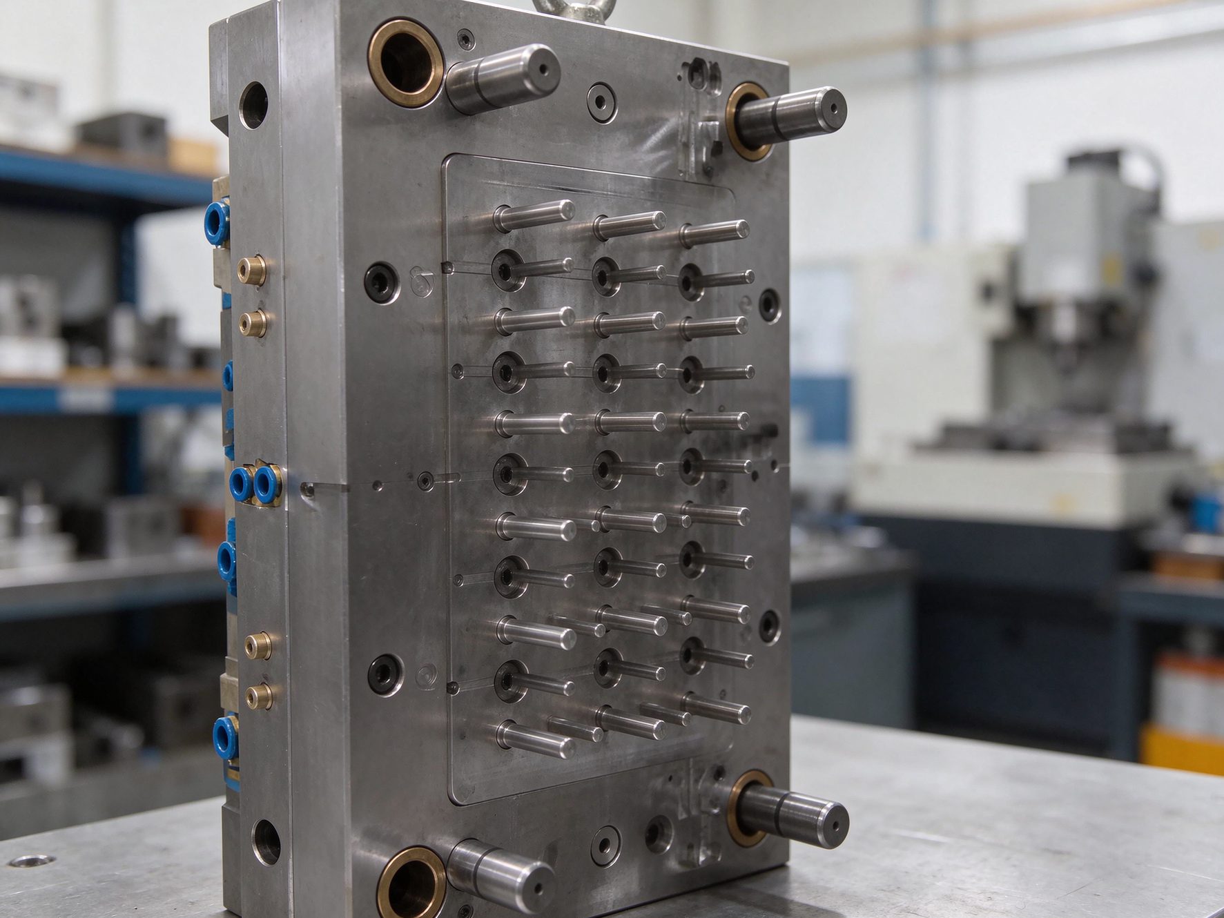
The cavity side forms the outer surface and the parting line. The core side carries a long, slim core that has to survive injection pressure, cool from the inside, and release without dragging on the wall it has just formed. Thirty-two of those cores sit in one block, and each one has to behave like the other thirty-one.
That shape changes the priorities. Wall thickness matters more than the outside profile, because a core that shifts by a few hundredths of a millimetre changes the wall on both sides at once. Cooling matters more than metal removal rate, because a hot core lengthens the cycle and pulls the part out of shape when it is ejected.
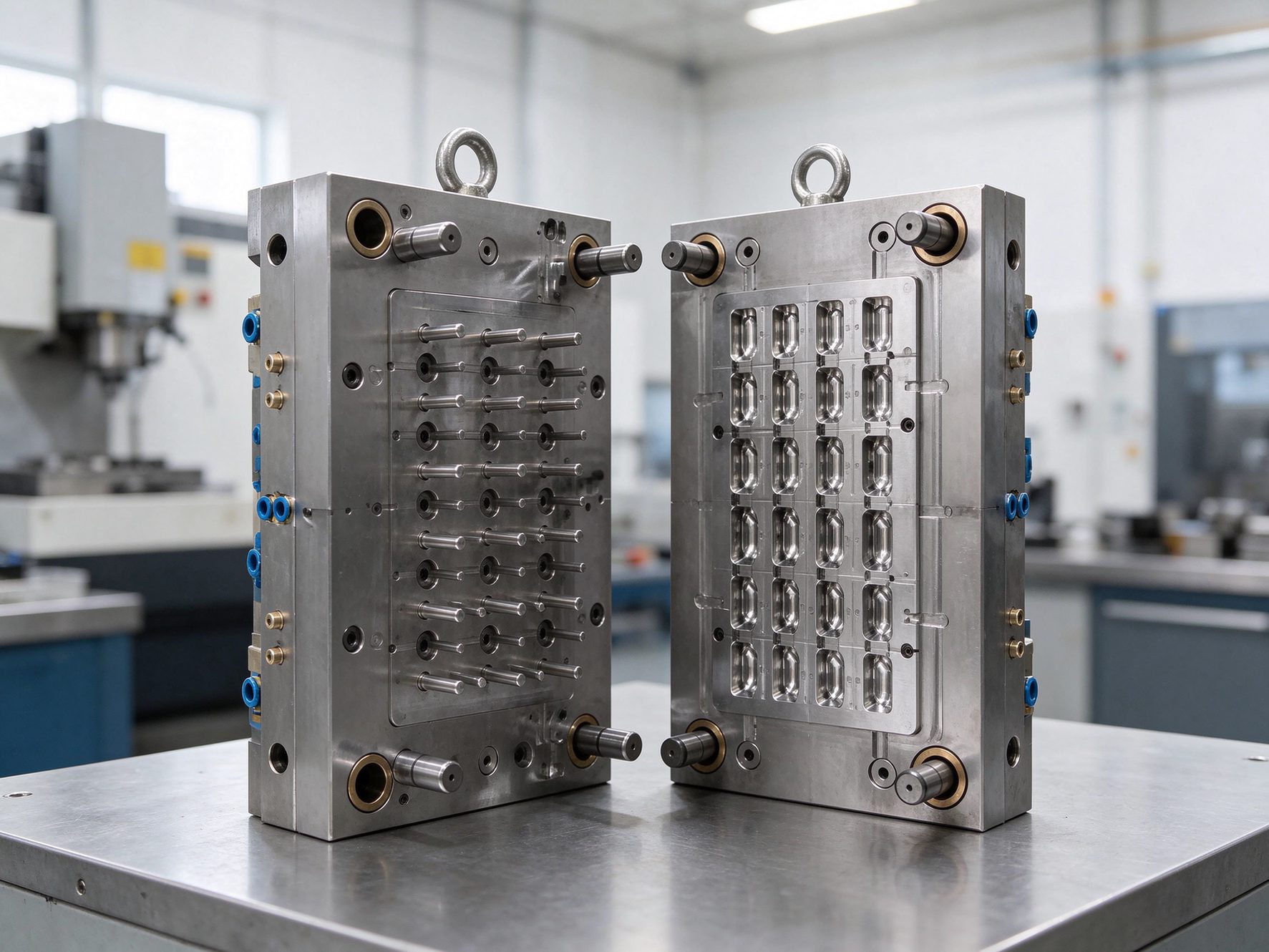
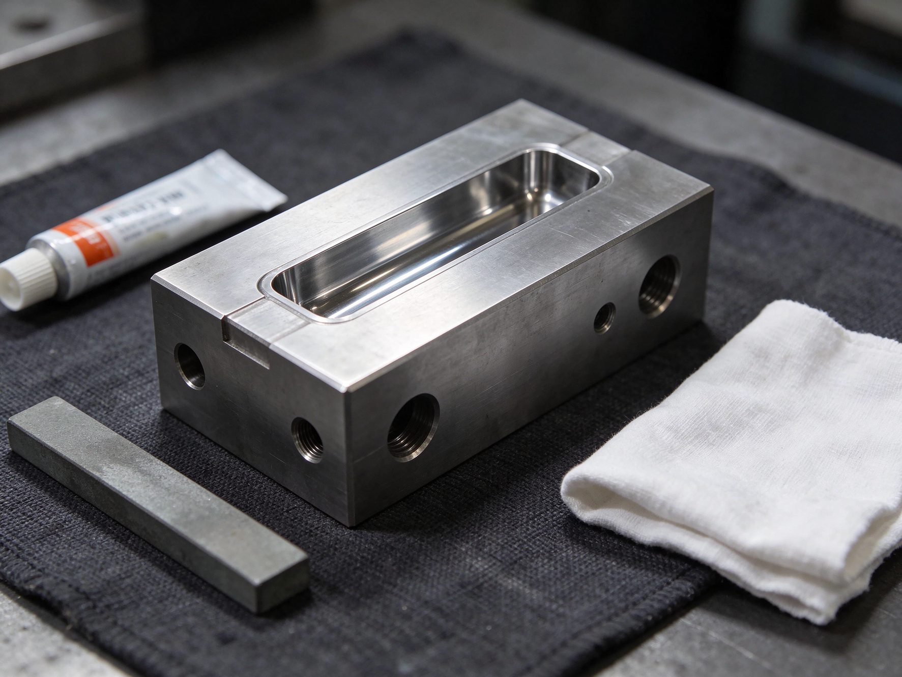
The tool in the photograph is the finished article: cavity block on the right, core side on the left, water fittings on the side of both plates, guide pillars at the four corners. What the photograph cannot show is the sequence that produced it, which is the rest of this page.
What the buyer put in writing
The order was fixed on a drawing, not on a description. These were the acceptance points.
| Requirement | What it meant in the tool | Where it was checked |
|---|---|---|
| Cavity dimensions | The steel dimensions that form the part, held to ±0.01 mm where the tool drawing marks it | CMM on the cavity block |
| Cavity-to-cavity consistency | Every cavity measured against the same datum, not against its own reference | CMM comparison list, cavity by cavity |
| Core and cavity fit | Core position, guide clearance and shut height after assembly | Fit check and pin gauges at assembly |
| Wall thickness | Core position inside each cavity, not the nominal wall alone | Sample measurement at T1 |
| Surface | Polish on the working faces, no rounded edge at the parting line | Visual against the agreed sample |
| Gate and vestige | Gate position and the finish left on the part after trimming | First shots, then trimmed samples |
| Documentation | Steel certificate, hardness record, dimensional report, trial report | Handover pack |
Acceptance points for this tool. The drawing numbers behind them stay with the customer.
Five places this tool could go wrong
None of these are solved by machining harder or polishing longer. They are solved in design, sequence and measurement.
-
A slim core bends under pressure
A long core acts like a beam. Injection pressure pushes it sideways, the wall on one side thickens and the wall on the other thins, and the part is out of tolerance in a way the plate cannot show. The answer starts before the first cut: core support, gate position and fill balance. A stiffer core that still fills unevenly moves the problem, it does not remove it.
-
Cavity 27 is not cavity 1
Thirty-two cavities mean thirty-two versions of the same dimension. If each cavity is cut and checked against its own reference, the tool can pass at the bench and still send rejects down the line. One datum, one comparison list, and the same characteristics measured on every cavity is what makes the block one tool instead of thirty-two tools in a frame.
-
Alignment across a long fit
The core has to enter the cavity with clearance small enough to hold the wall and large enough to survive a warm tool. The guide pillars set the position; the fit sets the rest. On a deep core, a small tilt at the base becomes a large offset at the tip, so the alignment is checked at assembly, not assumed from the machining report.
-
Polishing a deep pocket without moving the edge
Polish removes steel. Hand work at the bottom of a deep cavity can round the edge at the top and change the outline of the part. The allowance is left before the finishing cut, the edge is protected during polishing, and the working faces are worked in the draw direction so the part releases instead of dragging.
-
Fill balance across four columns
A runner that fills the first column early and the last column late gives different shrinkage along the block: the early cavities sink, the late ones burn or short. Venting has to follow the fill pattern, and the runner is sized for the last cavity, not the first. This is settled in the flow review, before steel is cut.
Decisions that shaped the build
Five choices carried most of the risk on this tool.
Core and cavity as a pair
The two halves were machined and measured together. A cavity dimension only means something next to the core dimension that answers it, so treating them as two independent parts invites a fit that has to be corrected by hand. The pair is the unit of work, and the pair is the unit of inspection.
One datum through the pair
The datum was set once and carried through rough machining, finishing, EDM and measurement. Changing the reference between operations is how a block ends up correct in each step and wrong as a whole. On a 32-cavity layout, that error shows up as a drift across the block, not as a single bad cavity.
Three axes where three axes are enough
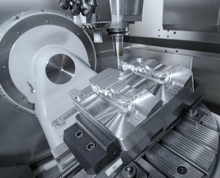
Most of the cavity and core work on this tool ran on three axes, with 3+2 indexing for the angled walls. Five-axis was used where the cutter had to reach a wall without tilting the part. A mold does not need five axes on every face, and pretending otherwise adds cost without adding accuracy.
Polish planned as a dimension
Polishing stock was left in the finishing cut, and the sequence ran from the deepest face outward so the edge stayed where the drawing put it. Polish is a dimensional operation on a tool like this, not a cosmetic step at the end.
A trial plan before the first cut
Before steel was cut, the trial was defined: which cavities, which characteristics, which instrument, and what would count as a pass. That plan decides where the steel-safe allowance is left, because a dimension that cannot be moved later cannot be corrected at T1.
Build sequence
Nine stages, in the order they ran on this tool.
Drawing review and DFM
Draft, wall, gate, ejection and the critical dimensions reviewed together. The issue list is agreed with the customer before steel is cut.
Tool design and 2D
Assembly, parting line, cooling layout, ejection and the dimension chain. The drawing that the shop works to, not the part drawing.
Steel order and incoming check
Grade and hardness range confirmed against the resin and the volume. Mill certificate and grade marking checked on receipt.
Rough machining and stress relief
Stock removed in stages, with stress relief before finishing so the block does not move after the last cut.
Heat treatment
To the specified range at a qualified supplier. Hardness verified on the part, with the record returned to the project file.
Finish milling and grinding
Three-axis and 3+2 work on the cavity and core, five-axis where the wall needed it. Locating and mating faces ground.
EDM
Wire EDM for sharp-cornered profiles and inserts, sinker EDM for detail a cutter cannot reach. Recast layer removed before polishing.
Polishing and fitting
Working faces polished to the agreed finish, edges protected, slides and ejectors fitted, cooling circuits pressure tested.
Trial and release
T0 on the intended press with the intended resin, then T1 with samples from each cavity measured. Corrections cut, report updated, tool released.
Steel and heat treatment
The steel choice is a wear decision. The certificate is what makes it a fact.
This tool was ordered in hardened tool steel, with the grade and hardness range fixed in the order. The grade is chosen against three things: what the resin does to the steel, how many cycles the tool has to survive, and how much polish the part needs. A glass-filled grade wears a cavity, a corrosive grade attacks it, and a high-polish surface needs a steel that can take the finish without tearing.
Hardness is checked after heat treatment, on the part, at a stated place, and recorded next to the mill certificate. Arriving hardness is not specified hardness: a block can arrive marked correctly and still measure outside the range after treatment, which is why the check is done rather than assumed.
Two details decide whether the hardness survives the rest of the build. Stress relief has to happen before finishing, or the block moves after the last cut. EDM recast has to be removed before polishing, or the surface looks finished and fails at the first thousand cycles.
| Grade family | Typical use on a tool |
|---|---|
| P20 | General cavity and core work, machines well, holds a good polish |
| 718H | Better homogeneity and polishability than plain P20, visible parts and larger blocks |
| H13 | Wear resistance and hot work, abrasive resins and high-volume tools |
| S136 | Corrosive resins such as PVC, and high-polish surfaces |
| NAK80 | Fine texture and appearance parts, good polishability |
| 45# / S50C | Structure plates only, never a cavity or core material |
The family used on this tool is recorded in its order, with the hardness range and the place it is measured.
Inspection: steel first, then the part
A cavity that measures correctly in steel can still produce a part out of tolerance. Both stages are measured, on the same characteristics.
| Check | Method | Record |
|---|---|---|
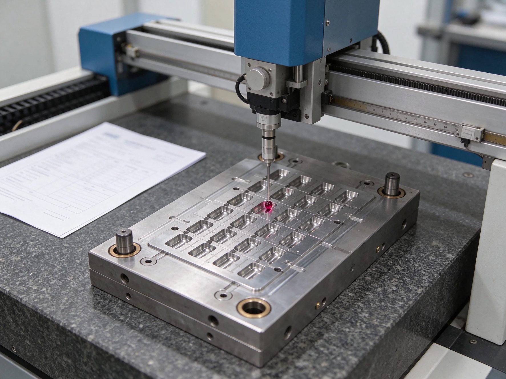
| Cavity and core dimensions | CMM on the finished steel, nominal against measured | Dimensional report, dimension by dimension |
| Cavity-to-cavity comparison | Each cavity measured against the same datum | One list covering all 32 cavities |
| Core and cavity fit | Pin gauges and fit check after assembly | Assembly record with clearances |
| Cooling circuits | Pressure test on both plates | Test record with pressure and time |
| Hardness | Tester on the part, at the stated place | Hardness record with mill certificate |
| Wall thickness and part dimensions | Samples from every cavity, same characteristics | T1 report, cavity identified per sample |
| Surface and edges | Visual against the agreed sample | Polish and texture note |
The measuring instrument is named in the report for a reason: a number without a method cannot be checked by anyone else.
What was handed over
A tool is only finished when the next person can run it without calling the person who built it.
The tool was released after the trial was approved. The report from that trial lists each cavity against the same characteristics, so a later question about a dimension can be settled with a record rather than a memory.
The handover pack for this build followed the same list used on other tools: the tool drawing, the steel certificate, the hardness record, the T1 report with cavity identification, the process sheet used at trial, and the maintenance points that matter for this geometry.
Two items are deliberately absent from this page. The customer and the application are not published, and the part drawing, resin grade and order volumes stay in the project file. Publishing a tool without publishing someone else's drawing is the line we hold.
Where the work happened
Machining, EDM and polishing of the cavity and core run in our mold shop, so a correction does not wait for a third party.
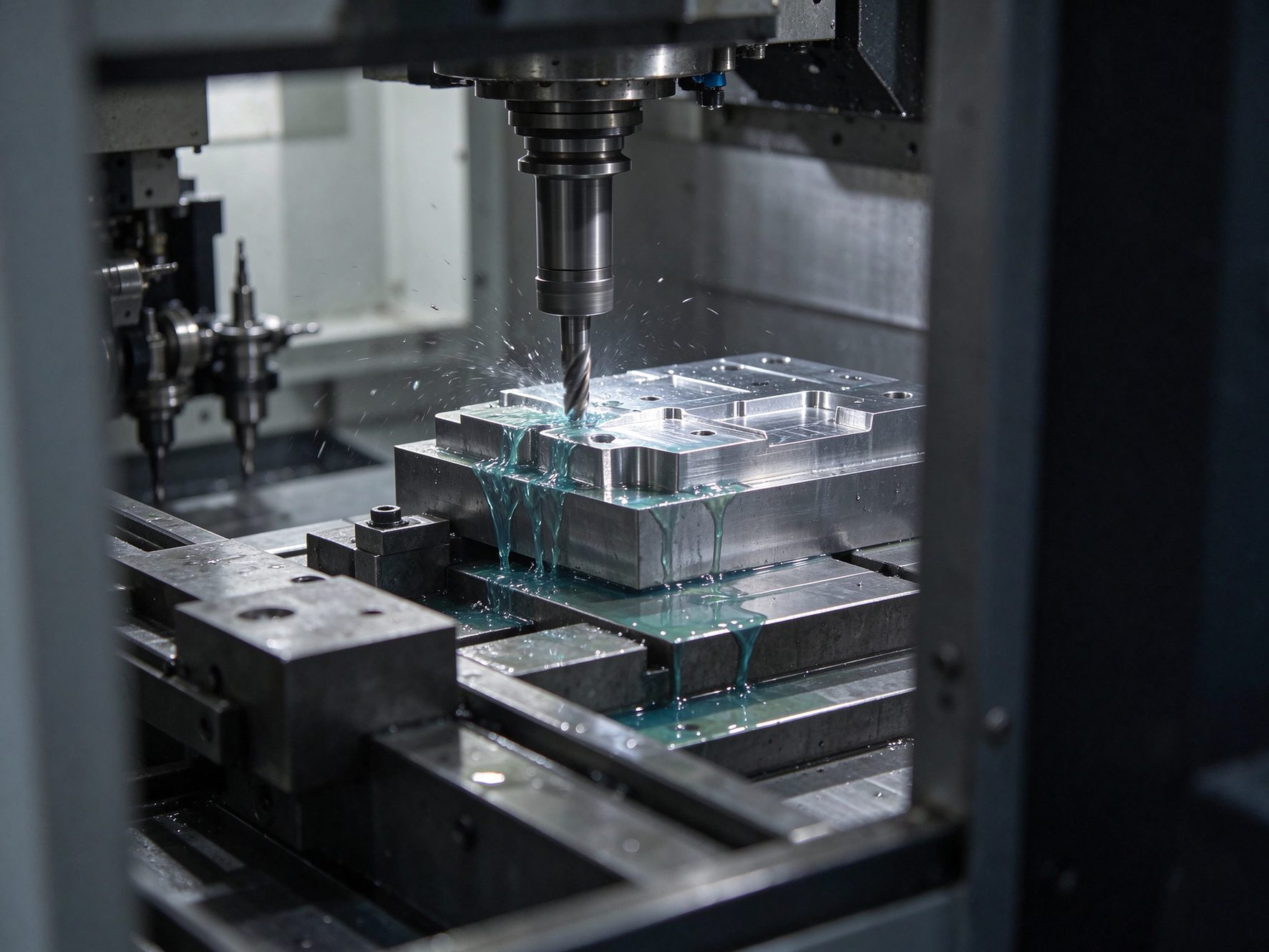
Machining, EDM and polishing of the cavity and core are done in our mold shop. That matters for a multi-cavity tool: when T1 shows a dimension that needs to move, the correction is a scheduling decision rather than a negotiation with an outside shop.
Heat treatment and texture work go to qualified suppliers, and the records come back to the project file. We do not describe those steps as if they happened under our roof, because the certificate is what the customer will rely on later.
The result is a build where the parts that need to stay together stay together, and the parts that need a specialist get one.
Polish is where a tool like this is most often hurried, and where a hurry is most expensive. A rounded edge at the parting line shows on every part for the life of the tool, and no amount of later inspection removes it.
The working faces are polished in the draw direction, the edges are protected, and the finish is checked against a sample rather than described in words. If the part needs a texture, the texture is agreed before the steel is finished, because texture and polish take different allowances.
Related capabilities
The pages behind this build, for the parts of a project that come before and after the tool.
Questions this page usually raises
Short answers, written for the person who has to defend the decision to a colleague.
What is a 32-cavity injection mold?
Why use 32 cavities for a small part?
What tolerance applies to the cavity?
How is cavity-to-cavity variation checked?
What does hardened tool steel mean on this tool?
Which mold steel grades do you work with?
Why polish the cavity, and how is the finish controlled?
What happens at T0 and T1?
Can a mold be corrected after trial?
Do you build the mold and run production?
What do you need to quote an injection mold?
How long does a multi-cavity mold take to build?
Send the drawing, not the description
A mold is quoted against a drawing, a resin and a volume. If you send those three, the reply can be specific about the cavity count, the steel, the trial plan and the documents you will receive. If the part is still moving, send it anyway and ask for a DFM review first.
- Part drawing or 3D model, with tolerances and critical surfaces
- Resin grade, and whether it is filled or flame retardant
- Expected first-year volume and the press you plan to run
- Cavity count you have in mind, or the target part price
- Polish, texture or cosmetic requirement, with a sample if one exists
- Documents needed at handover: steel cert, hardness, CMM, T1, PPAP