5-Axis CNC Machining of a Precision Flanged Component
How we plan, machine and inspect a flanged part with features on several faces — from drawing review to a dimensional report. This page shows our project-record format; the numeric fields and photos are examples to be replaced with verified project data before publication.
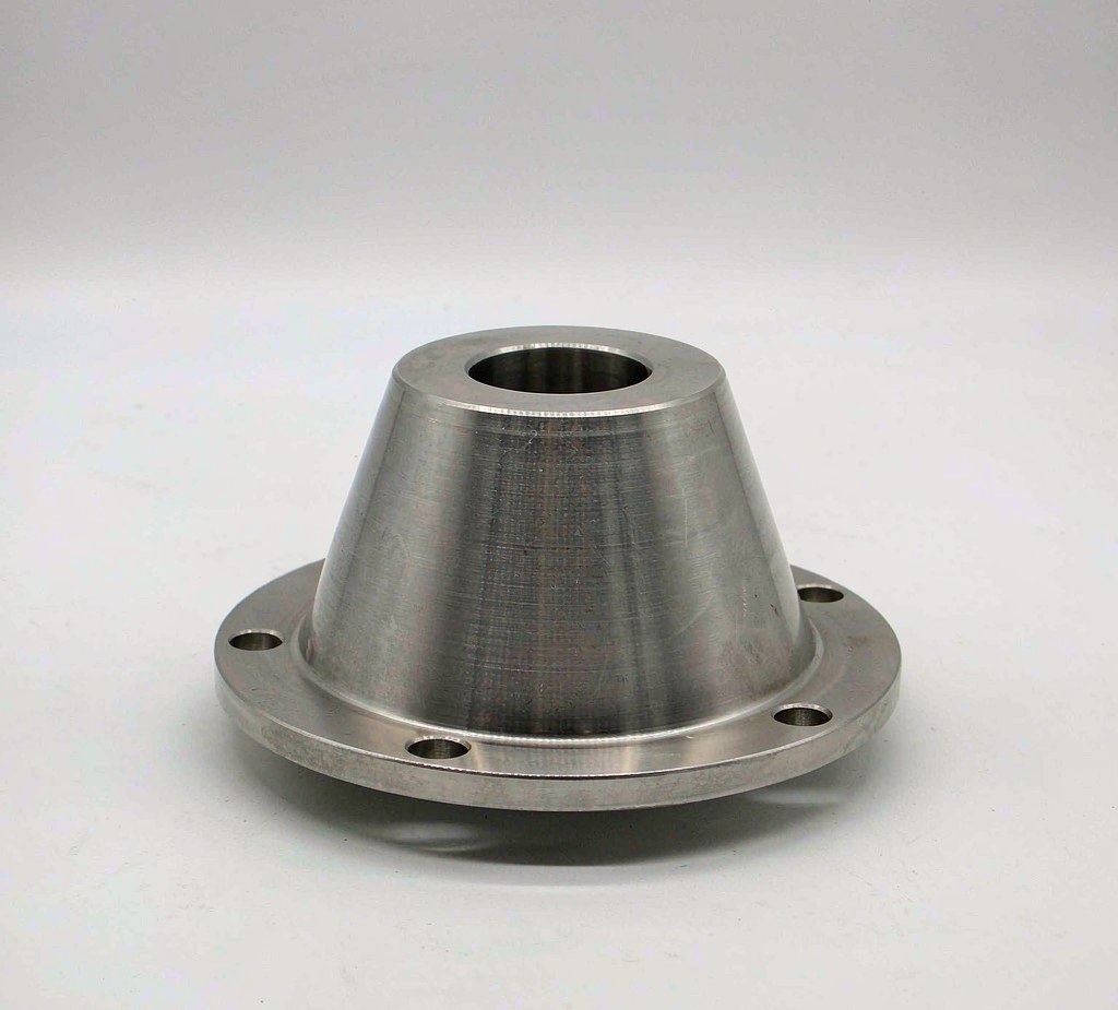
A flanged part is not difficult because of any single feature. It is difficult because the bolt-circle, bore, sealing face and hub must relate to each other. Our approach is to finish critical features in as few setups as possible, define datums from the drawing, and inspect the relationships — not just the individual sizes.
Project at a glance
This block is the summary a purchasing engineer reads first: what kind of part, which process, the review points and the deliverables. Values marked example field are placeholders that must be filled from the real project record before publication.
Project snapshot
We do not publish a fixed tolerance, cycle time or price for a part we have not verified. These fields are shown to explain what a complete record contains.
Part overview
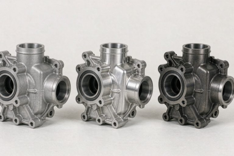
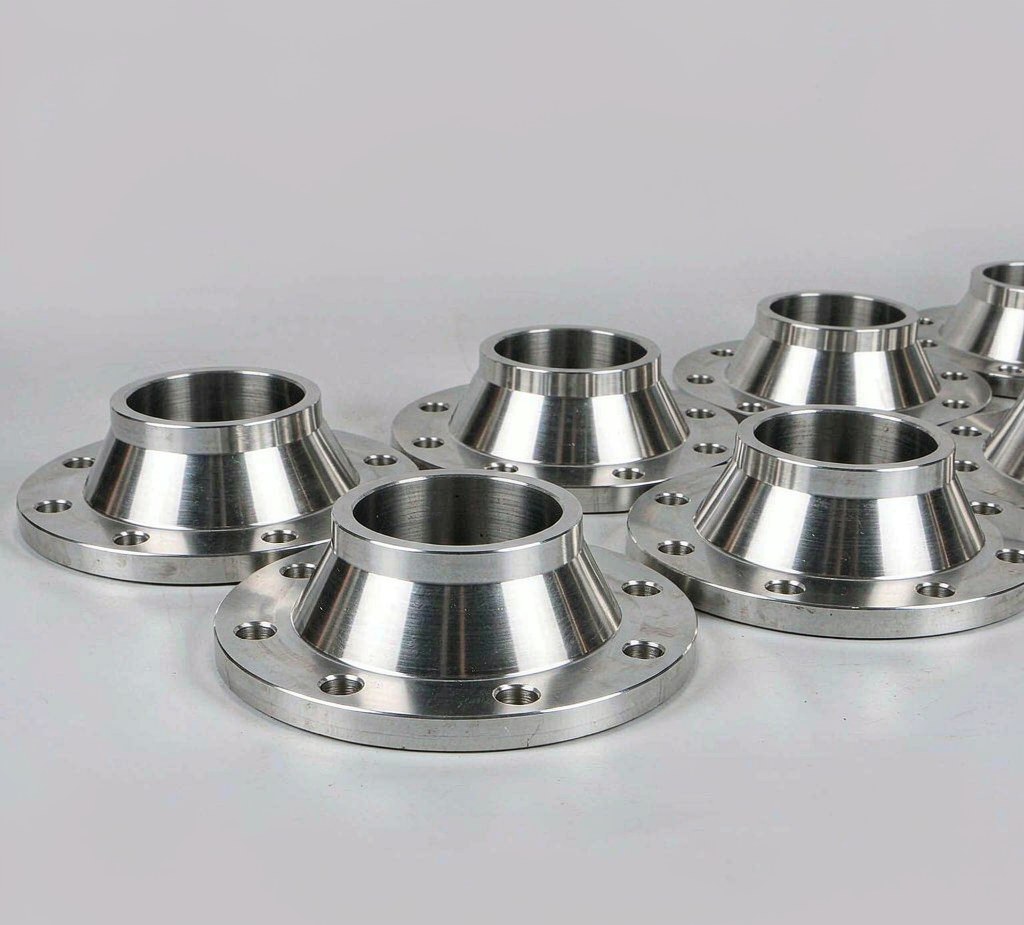
The part in this study is a flange-type component: a flat circular flange with a bolt-hole pattern, a tapered central hub and a through bore. Features sit on more than one plane and at more than one angle, which is typical of parts that use a 5-axis machine.
Mounting interface
A flat annular face carrying a circle of bolt holes. It locates the part against a mating component, so face flatness and hole position matter more than the outside diameter.
Tapered centre boss
A raised, tapered hub adds stiffness around the bore. The taper has to be machined at the correct angle and blend cleanly into the flange face.
Central through hole
The bore often receives a shaft, bearing or pipe. Its size and its position relative to the bolt circle are usually the most critical features on the drawing.
Holes & face details
Bolt holes, counterbores, seal grooves or small radii can be present. Each one adds a tool approach and may need a separate setup if the machine cannot reach it.
Customer requirements
A useful project record separates what the drawing requires from what the shop prefers. We read the drawing first and write down the features that control fit and function, then plan the process around them.
| Requirement | Why it matters | How it is controlled |
|---|---|---|
| Bolt-hole position | Sets where the part bolts onto the mating face | Drill on a rotary axis; inspect hole positions on a CMM |
| Bore diameter | Controls fit with a shaft, bearing or pipe | Finish-bore in one setup; check with a bore gauge |
| Bore-to-hole relationship | Keeps the centre aligned with the mounting pattern | Machine critical features without re-clamping; inspect as a datum relationship |
| Sealing-face flatness | Affects seal contact and leakage | Finish-face last; check flatness with a surface plate or CMM |
| Hub angle | Sets the shape and any mating clearance | Use the tilting axis; verify the angle on the drawing |
| Surface finish | Affects seal life and cleanability | Select tool and feed; check with a comparator |
Swipe the table to see all columns.
Machining challenges
These are the real difficulties a flanged part creates. Understanding them is more useful to a buyer than a machine model number, because the same challenges appear on many different parts.
Features on many faces
The flange face, hub taper and bore point in different directions. On a 3-axis machine each new face means a new setup, and each setup adds positioning error.
Repeated clamping
Taking the part off and clamping it again can shift the datum. That is how the bolt circle drifts away from the bore even when each size is correct on its own.
Tool access
A deep bore, an angled hub or a feature near the flange root can be hard for a straight tool to reach. The tool must approach at an angle without hitting the fixture.
Distortion & finish
Thin flanges and long hubs can move under cutting force or heat. Finishing strategy and tool sharpness decide whether flatness and finish hold after the part is freed.
Engineering solution
We solve these problems with planning, not by naming a machine. The steps below are the decisions a project engineer makes before the first cut.
- Define datums from the drawing. Choose the faces and bore that the inspection plan will measure from.basis for all setups
- Group features by direction. Put faces that share an approach into the same setup to reduce re-clamping.fewer setups
- Plan the tool approaches. Check that the tilting axis can reach the hub and bore without the holder hitting the part or fixture.access confirmed
- Choose the workholding. Clamp on a non-critical area so the datum faces and bolt circle stay open for machining and measurement.datums kept clear
- Separate roughing and finishing. Remove bulk material first, then take light finishing passes so heat and force do not move the part.stable finish
- Agree inspection before cutting. Decide how each critical feature will be measured and recorded in the quality plan.measured to drawing
Machining process
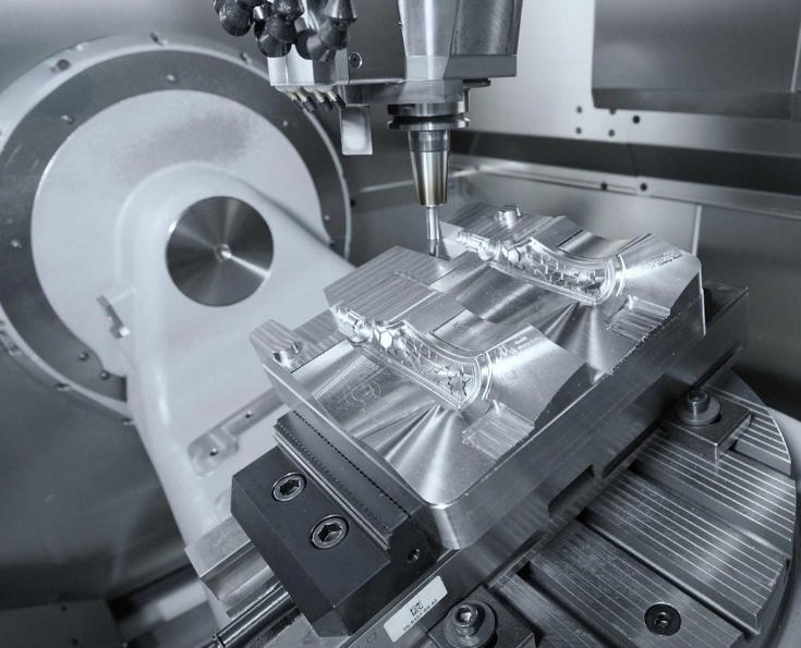
A build-to-print part follows a controlled sequence. The exact steps depend on the drawing, but the order below is typical for a flanged component with a bore and a bolt circle.
| Step | Operation | Purpose |
|---|---|---|
| 01 | Material & blank review | Confirm grade and size against the drawing before cutting |
| 02 | First setup — face & datum | Establish the reference face and bore for later operations |
| 03 | Rough the hub & profile | Remove bulk stock while leaving finish allowance |
| 04 | Second setup — bolt circle | Drill and finish the bolt holes relative to the datum |
| 05 | Finish bore & sealing face | Bring critical features to the drawing requirement |
| 06 | Deburr & clean | Remove edges and cutting residue before inspection |
| 07 | Dimensional inspection | Measure and record critical features against the drawing |
Swipe the table to see all columns.
Material & surface finish
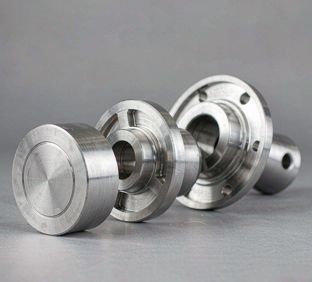
Material and finish are chosen for the working environment, not for the machine. The table shows common options for this type of part. The grade and finish for any real order come from the customer specification.
| Material | Typical reason to choose it | Common finish |
|---|---|---|
| 304 stainless | General corrosion resistance and cost control | Machined finish, passivation available |
| 316 stainless | Better resistance in chloride or marine air | Machined finish, passivation available |
| Carbon steel | Strength and lower cost for protected environments | Machined finish, coating per spec |
| Aluminum 6061 | Light weight and easy machining | Machined finish, anodizing available |
Swipe the table to see all columns.
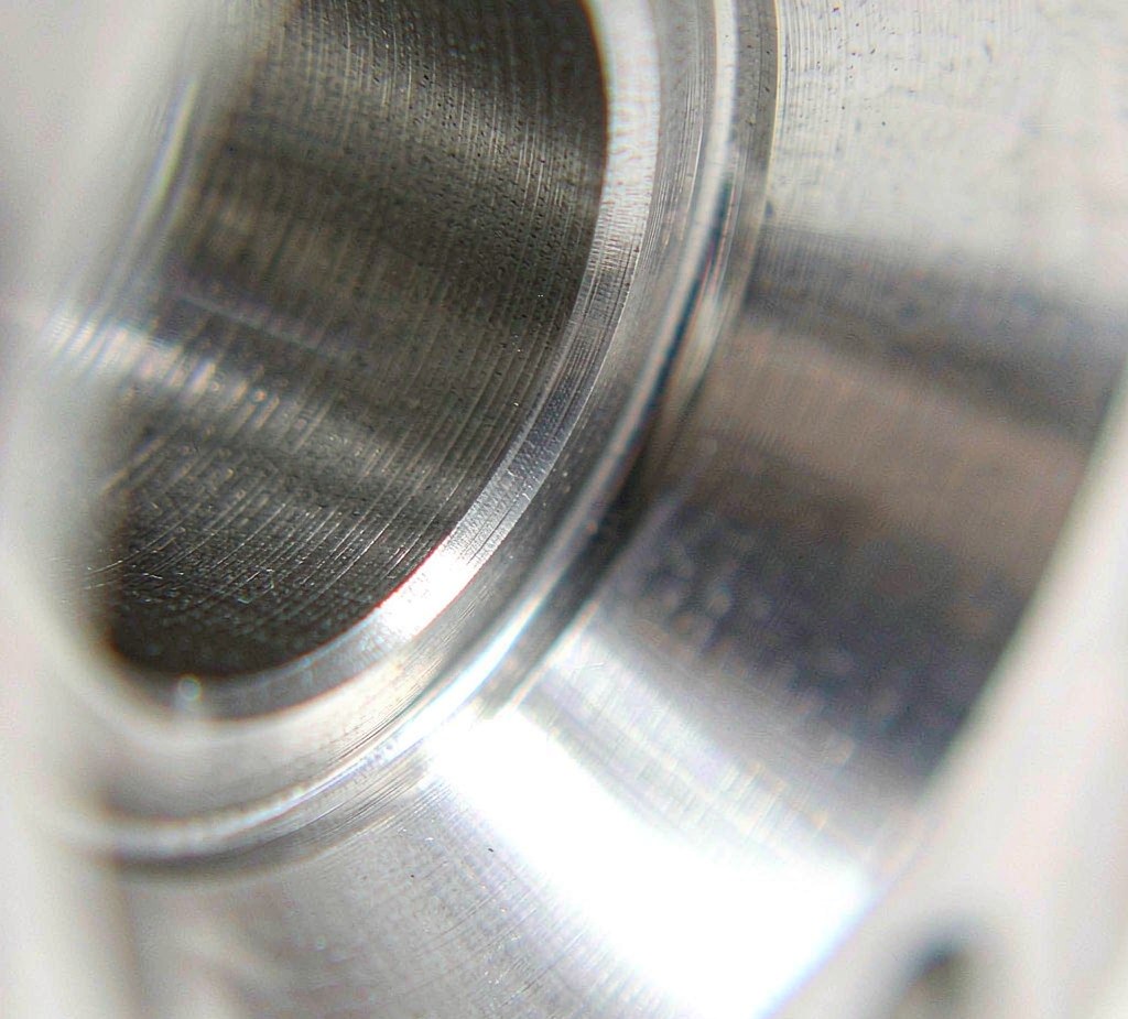
Quality inspection
A buyer trusts a case study when it shows how the part was checked, not only how it was made. We record the features that control fit and function and keep the method consistent for repeat orders.
First-piece check
The first piece is measured against the drawing before the batch continues. A first-article report can be provided when agreed in the quality plan.
Feature measurement
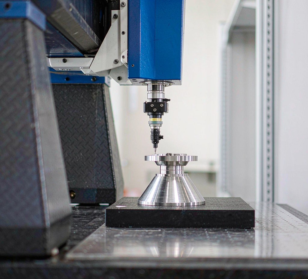
Bore size, hole positions, face flatness and hub geometry are measured with suitable gauges or a coordinate measuring machine.
Report & traceability
Inspection results, material certificates and process records can be supplied with the order so the part is traceable to its drawing revision.
Consistent method
The same setup and inspection plan are kept for repeat batches, so the same features are measured the same way each time.
Project results
In a completed record this block states what was delivered, checked and shipped — using verified figures only. Below is the format we use, with example fields clearly marked.
| Outcome field | What is recorded | Status on this page |
|---|---|---|
| Part delivered | Quantity and revision shipped | example field |
| Critical features | Features inspected and result vs drawing | example field |
| Inspection report | First-article / dimensional report reference | example field |
| Surface & material | Final finish and material certificate | example field |
| Delivery | Shipping terms and date | example field |
Swipe the table to see all columns.
Why these fields are blank
- We do not publish a pass rate, tolerance result, cycle time or delivery figure without the verified project record.
- Every number here must be traceable to an inspection report or drawing before this page describes a specific completed order.
- The process and engineering sections describe real manufacturing practice; only the project-specific results are placeholders.
What we can and cannot claim
Clear boundaries help both buyers and engineers. This section states exactly what this page supports.
Our method for planning 5-axis work on flanged parts, the type of features we inspect, the material and finish options we can provide, and the RFQ information we need from a drawing.
A specific named customer, an order quantity, a measured tolerance result, a delivery time or a price for this part. No industry certification for this part is implied by the process described.
Related capabilities
Explore the processes and references connected to this type of part.
FAQ & Request a quote
Why use 5-axis CNC machining for a flanged component?
A flanged part often has features on several faces: a sealing face, a bolt-hole circle, an angled hub and a bore. A 5-axis setup can reach these faces by tilting the tool instead of unclamping the part. Fewer setups mean fewer chances to lose position between the bolt-circle and the bore. For a build-to-print part, that helps protect the relationship between features.
What material can a flanged component like this be made from?
Flanged parts are common in stainless steel such as 304 and 316, carbon steel and aluminum grades such as 6061. The right grade depends on the working environment, strength needs and budget. In this case study the material line is shown as an example field. Confirm the exact grade from the drawing or with your engineer before quoting.
Can Goldcattle machine this part from our drawing?
Yes. Send a 2D drawing and a 3D model, and tell us the material, the quantity and which features are critical. We review the datum scheme, tool access and inspection method before we quote. This page describes how we document a project; the actual dimensions and results are confirmed from the real project record.
How do you check the critical dimensions of a flange?
We check the features that control fit and function first: the bore diameter, the bolt-hole positions, the sealing-face flatness and the relationship between the hub and the flange. Depending on the drawing, this can use a coordinate measuring machine, a height gauge, pin gauges and surface comparators. The inspection method is agreed in the quality plan before machining.
Do you support prototypes and repeat orders?
We make one-off prototypes and follow-on batches under the same drawing revision. First-article inspection can be provided for the first piece, and the same setup and inspection plan are kept for repeat orders so results stay consistent. The sample and batch quantities shown on this page are example fields, not confirmed order figures.
What files do I need to send for a quote?
A 2D PDF drawing with dimensions and tolerances is the minimum. A 3D STEP or native model helps us check tool access and geometry. Also send the material grade, required quantity, surface finish and any special inspection or documentation requirements. We review DFM and return a quote.
Is this an actual completed Goldcattle order?
This page is a case-study format showing how we record a 5-axis flanged-part project. It explains the part, the manufacturing challenges, the process and the inspection approach. The numeric values and photos must be replaced with verified data and real project photographs before this page is published as a specific completed order.
Have a flanged part to machine from your drawing?
Send the drawing and material grade. We review datum strategy, tool access and inspection, then return DFM feedback and a quote.
Upload your drawing → DFM review and quote based on the drawing. Documentation packages and inspection reports are available on request.