Robotic End Effector CNC Parts, Built to Your Drawing
Custom machined metal and engineering-plastic parts for the tools mounted on industrial robot arms, selected by the automation task they serve and made to your drawings.
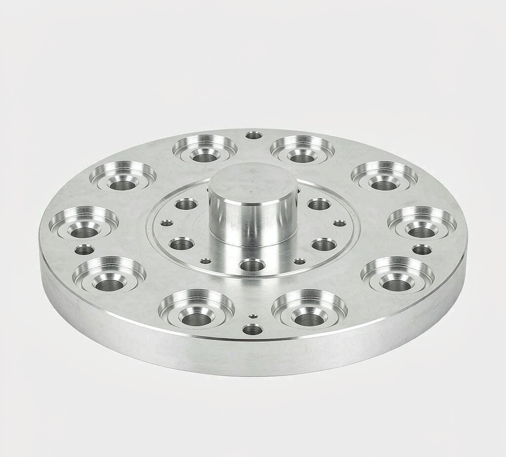
What are robotic end effector CNC parts? They are custom machined mechanical components used to connect, grip, position and support tools on industrial robot arms. Common parts include gripper fingers and jaws, robot flange adapter plates, EOAT mounting plates, tool changer adapters, vacuum manifolds, sensor brackets and locating fixtures. Goldcattle machines these metal and engineering-plastic components from customer drawings and CAD models. Reviews focus on interface geometry, datum relationships, material choice, critical dimensions, surface finishing and inspection. Complete gripper system design, pneumatic integration, robot programming and cell commissioning are outside our machining scope.
01 · What we make for robotic end effectors
You can order EOAT parts by function and by the automation task they support. We review each part against your drawing before confirming we can machine it. The categories below describe work we can assess; they are not a stock catalogue.
Fingers & jaws
Custom gripper fingers, parallel jaws, jaw inserts and replaceable contact pads machined to the workpiece and contact requirements.
Plates & adapters
Robot flange adapter plates, EOAT mounting plates, tool changer adapters, spacer blocks and riser plates.
Vacuum & air blocks
Vacuum manifold blocks, air distribution blocks, suction cup mounts and port connection blocks with internal passages.
Sensor & vision parts
Camera mounting plates, sensor brackets, force sensor adapter flanges and cable routing brackets.
Frames & fixtures
Lightweight EOAT frames, positioning nests, guide blocks, support brackets and wear components.
Metal & plastic
Aluminum, stainless steel and engineering plastics such as POM, nylon, PEEK and PTFE, selected per part and contact condition.
02 · End effector, gripper and EOAT are not the same
Buyers often use these words together, but they describe different scopes. Knowing which one you need makes a request clearer and avoids quoting the wrong thing.
Swipe the table to see all columns.
| Term | What it means | Typical contents |
|---|---|---|
| End effector | The device on the robot arm that performs a task | Gripper, vacuum tool, welding tool |
| Gripper | A tool that holds a workpiece by mechanical, electric or pneumatic means | Gripper body, jaws, fingers |
| EOAT | End-of-arm tooling: the wider tool assembly on the arm | Adapter plates, grippers, cups, sensors, brackets |
For a CNC supplier this matters because a buyer may need only one machined component, such as a pair of fingers or an adapter plate, rather than a complete tool. That is the scope this page covers.
03 · Parts by automation application
Engineers often search by the task their robot performs, not by a part name. Each application below lists the machined parts commonly involved and the features that matter. This is a selection guide, not a claim that we supply complete systems.
Loading CNC machines
Gripper fingers, machine loading adapters, workpiece nests and sensor brackets. Focus: grip stability and materials that tolerate chips and coolant.
Sorting and transfer
Lightweight adapter plates, gripper jaws, cup mounts and positioning brackets. Focus: low weight, contact position and surface protection.
Packing and palletizing
Vacuum manifold blocks, suction cup mounts, tooling frames and air blocks. Focus: cup layout, air passages, sealing faces and weight.
Insertion and fitting
Precision adapter plates, alignment blocks, gripper fingers and assembly nests. Focus: locating holes, mounting faces and fit dimensions.
Inspection and sensing
Camera brackets, sensor adapter plates, optical bases and cable guides. Focus: mounting angle, rigidity, hole position and clearance.
Welding and process tools
Torch mounting brackets, tool adapter plates and positioning fixtures. Focus: mounting datum, rigidity and heat-environment material choice.
04 · Gripping parts and contact geometry
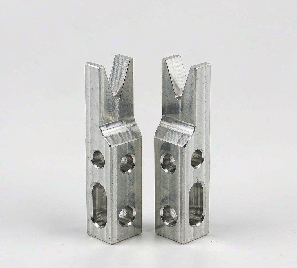
A gripper finger is judged not only by its own size but by how a pair works together on the workpiece. We review matched dimensions, contact shape and mounting positions before we quote.
Two fingers should meet the workpiece consistently. We check paired dimensions and mounting features against the drawing.
V-grooves, contoured faces and pads are chosen for the workpiece shape and surface condition.
Swipe the table to see all columns.
| Workpiece | Contact design focus |
|---|---|
| Polished aluminum parts | Avoid scratches and marks on the visible surface |
| Plastic molded components | Reduce contact damage; softer pads may be used |
| Steel components | Wear resistance and stable contact geometry |
| Cylindrical parts | V-groove or contoured contact |
| Irregular parts | Custom profile and locating features |
| Delicate products | Polymer pads or compliant contact design |
05 · Mounting and robot interface parts
An adapter plate sits between the robot wrist and the tool. Its value is in how accurately it locates the tool, not in how complex it looks.
Swipe the table to see all columns.
| Feature | Why it matters |
|---|---|
| Bolt circle / PCD | Defines where the plate bolts to the wrist and tool |
| Centering boss / register | Locates the plate concentrically to reduce offset |
| Dowel pin holes | Sets repeatable position between mating parts |
| Mounting face flatness | Reduces tilt when the tool is bolted on |
| Two-side pattern relationship | Keeps wrist and tool interfaces aligned to each other |
| Stack height | Affects the tool centre position on the robot |
ISO 9409-1 is a common standard for the circular mechanical wrist interface. It defines interface dimensions and designation to support mechanical interchange and mounting orientation. It does not define payload, and it does not replace the robot maker's specific interface drawing. Send that drawing with your request.
Where machine access and workholding permit, the centering boss, bolt circle and dowel features are machined from a common setup. When more than one setup is needed, datum transfer and feature relationships are controlled and checked during inspection.
06 · Vacuum and pneumatic parts
A vacuum manifold is more than a machined aluminum block. Its function depends on passages and sealing features that a flat outside view cannot show.
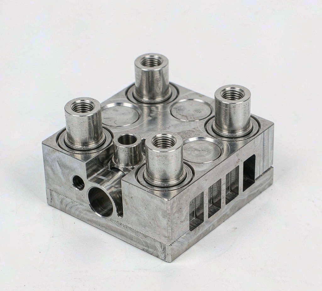
- Threaded ports — thread standard, size and depth are per drawing.
- Internal passages — cross-drilled holes must meet and stay open.
- O-ring grooves — groove size and surface finish follow the seal specification.
- Sealing faces — flatness and finish are checked against the drawing.
- Internal burrs and cleaning — passages are cleaned after machining.
07 · Sensor and vision mounting parts
Camera and sensor brackets hold optical equipment steady on a moving arm. Small errors in angle or position can change what a vision system sees.
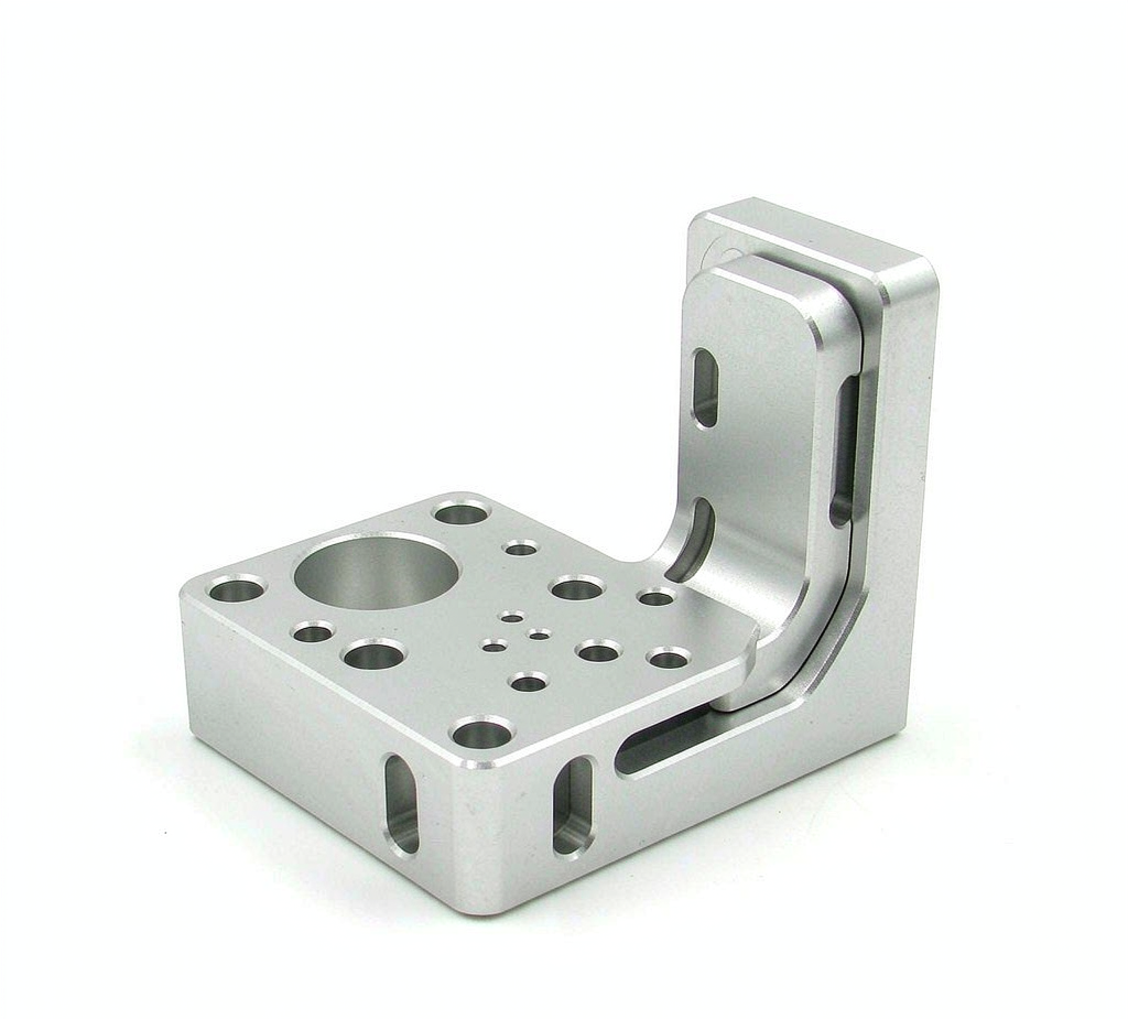
- Mounting position and angle — set by the drawing and checked after machining.
- Rigidity — section thickness and support are kept where load passes.
- Field of view — opening and clearance follow the sensor layout.
- Cable routing — passages and slots keep cables clear of moving parts.
These parts are machined to the approved design. Vision calibration and measurement performance belong to the system integrator.
08 · Material selection for EOAT parts
Material choice balances weight, strength, wear and the surface being contacted. A grade name alone does not guarantee a finished part will suit an environment.
Swipe the table to see all columns.
| Material | Typical parts | Selection note |
|---|---|---|
| Aluminum 6061-T6 | Adapter plates, brackets, mounting plates | Good all-round machining and cost balance |
| Aluminum 7075-T6 | Lightweight fingers, high-strength plates | Higher strength for weight; finish per environment |
| Stainless 304 / 316L | Corrosion-prone or wear parts | Grade chosen from the actual service environment |
| POM / nylon | Contact pads, locating nests | Low friction and less marking of workpieces |
| PEEK / PTFE | Special contact parts | Selected for temperature or chemical needs; not automatic compliance |
Lighter is not the same as thinner. We remove material from non-critical zones with pocketing and ribs, while keeping the sections that carry load. We machine to your approved design. We do not certify complete tool payload or fatigue life from machining alone.
09 · CNC process and DFM review
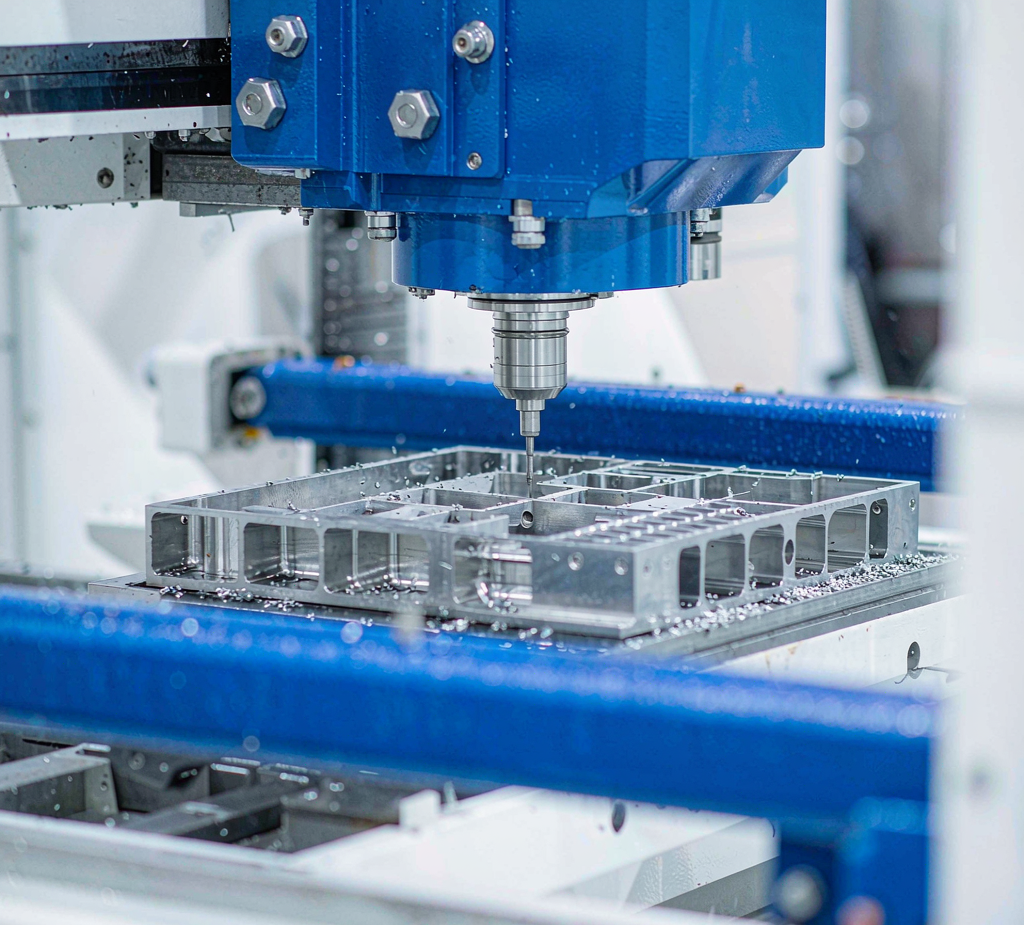
We choose the machining route from the part, not from a preference for more axes. A simple plate is often more economical on three-axis equipment.
Swipe the table to see all columns.
| Route | Good for | Buyer concern |
|---|---|---|
| 3-axis milling | Flat plates, pockets, hole patterns | Dimensions, hole position and cost |
| 4-axis milling | Features on several faces | Position between faces |
| 5-axis machining | Angled faces and complex shapes | Setup count and datum relationships |
| CNC turning | Round bosses, pins, bushings | Diameter and concentricity |
Before cutting we review tool access, thin walls, pocket depth, workholding and how the part will be measured. DFM questions are raised with you, not silently resolved on the machine. Contact-heavy polymer parts may suit 3D printing instead; we compare the routes when the design allows either.
10 · Finish, fit and inspection
Finishes are chosen for function and can change a fit. Anodizing and hard anodizing shift bore or boss dimensions; passivation applies to suitable stainless parts; bead blasting changes texture. We define critical dimensions on the finished part and agree which faces are masked.
Inspection is planned around the features that matter. Different parts need different checks.
Swipe the table to see all columns.
| Part | Typical checks |
|---|---|
| Adapter plate | Bolt circle, boss position, flatness, dowel position |
| Gripper fingers | Matched pair, contact profile, hole position |
| Vacuum manifold | Port threads, O-ring groove, sealing face |
| Sensor bracket | Mounting position, face angle, flatness |
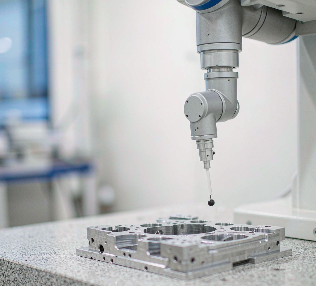
Available documents can include a dimensional report, CMM results for key features, a first article inspection report and material certificates when the project calls for them. Reports show what was measured; they do not replace grip-force, system repeatability or cell validation. From sample to repeat orders we work from the approved drawing revision, first article and inspection plan, with change control on any revision.
Send the drawing for a machining review. We check the interface, material and inspection requirements before we quote, and raise any DFM questions with you first.
Frequently asked questions
What CNC parts are used in robotic end effectors?
Robotic end effectors use many custom machined parts: gripper fingers and jaws, robot flange adapter plates, EOAT mounting plates, tool changer adapters, vacuum manifold blocks, sensor and camera brackets, locating nests and support frames. Goldcattle machines these metal and engineering-plastic components from customer drawings. We do not supply complete gripper systems, robot programming or cell commissioning.
Do you make custom gripper fingers and jaws?
Yes. We machine gripper fingers and jaws to drawing, including matched pairs. We review the contact profile, mounting hole positions and the workpiece surface before quoting. A polished aluminum part and a rough casting need different contact designs. We make the machined part; gripper stroke, clamping force and system validation stay with the equipment designer.
Can you machine a robot flange adapter plate to ISO 9409-1?
We machine adapter plates to the interface dimensions on your drawing, including the centering boss, bolt circle and dowel holes. ISO 9409-1 is a common standard for the circular mechanical wrist interface on industrial robots. It defines interface dimensions and designation. It does not state payload capacity and it does not replace the robot maker's specific interface drawing. Send that drawing for review.
Which materials are used for EOAT parts?
Common choices are 6061-T6 and 7075-T6 aluminum, stainless steel 304 and 316L, and engineering plastics such as POM, nylon, PEEK and PTFE. The right grade depends on the part, the contact surface and the environment. A material name alone does not make a part food-safe or cleanroom-ready. We confirm the grade and condition against your drawing before machining.
What tolerances matter most for EOAT components?
Different features need different control. Adapter plates depend on bolt circle position, centering boss, dowel holes and mounting face flatness. Gripper fingers depend on matched pair dimensions and contact profile. Vacuum blocks depend on port threads, O-ring grooves and sealing faces. We set tolerance feature by feature from the drawing, not as one blanket number.
Can CNC machining make lightweight EOAT structures?
Yes. Weight matters at the robot wrist, but lighter does not mean simply thinning material. We remove material from non-critical areas with pocketing and ribs while keeping the sections that carry load. We machine to the approved design. We do not certify a complete tool's rated payload, inertia limit or fatigue life from machining alone.
Is CNC machining better than 3D printing for EOAT parts?
It depends on the part and the quantity. CNC machining suits metal parts that need tight interface dimensions, thread quality and repeatable fits. 3D printing can suit complex lightweight shapes or low-volume polymer contact parts. We review strength, precision, contact surface and volume with you and suggest the process that fits. We offer both routes in house.
Can you machine vacuum manifolds and pneumatic blocks?
Yes. These blocks can include threaded ports, internal air passages, O-ring grooves, cross-drilled holes and sealing faces. We review internal burr removal and cleaning because passages must stay open and clean. We inspect the machined dimensions and agreed features. A vacuum leakage or suction test on the complete tool is arranged by the system integrator, not by part inspection alone.
How do finishes affect EOAT assembly fit?
Anodizing and hard anodizing change surface and can shift bore or boss dimensions. Passivation applies to suitable stainless parts. Bead blasting changes texture. Masking may be needed on locating faces and press fits. We define critical dimensions on the finished part, not only the as-machined part, and agree which faces are masked or finished after coating.
Do you support prototypes and repeat production?
Yes. Prototype orders start from one piece. After a sample is approved, we work from the same drawing revision, first article and inspection plan for repeat batches. Material, process and revision changes go through a control step. This keeps later orders aligned with the first approved part.
What should I send for an EOAT CNC quote?
Send a 3D CAD model and a 2D drawing with dimensions and GD&T. Include the current revision, material grade and state, quantity and inspection needs. For interface parts, add the robot model or flange drawing and any tool changer interface. For grippers, add the workpiece size, weight and contact location. Tell us the target delivery date and destination.
Do you manufacture complete robotic end effectors?
No. We manufacture the custom machined parts that go into an end effector. We do not design complete gripper systems, integrate pneumatic or vacuum systems, write robot programs or commission automation cells. Complete tool design, payload and grip performance validation remain with the system integrator or equipment builder.
Have an EOAT component to manufacture?
Send your 3D CAD model, technical drawing and robot interface requirements. We review the machining route, critical interfaces, material options and agreed inspection for your custom parts. STEP · STP · IGES · DWG · DXF · PDF. NDA on request.
Xiamen Goldcattle Plastic & Metal Products Co., Ltd. · Founded in 1998 · manufacturing to your drawings and samples.