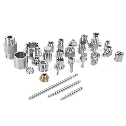
Custom CNC Machined Robot End Effector Components
The parts at the end of a robot arm have to fit the wrist, hold the workpiece and stay light. This page explains how we plan and check those things from your drawing. It also says clearly what we do not claim.
At a glance
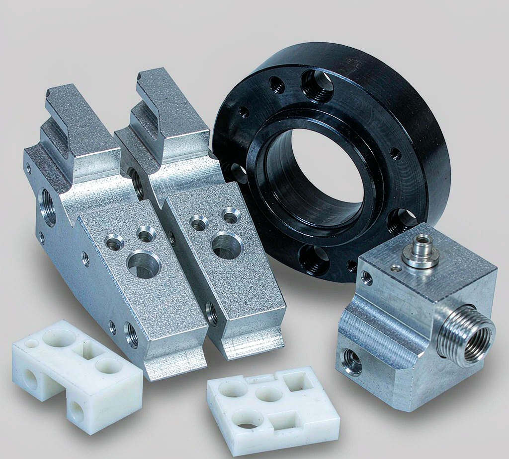
Custom CNC machined robot end effector components are the mechanical parts that mount to a robot wrist and hold, move or sense a workpiece. We make them from your drawing with milling, turning, drilling and tapping. The features that decide whether the tool works are the wrist interface, the contact geometry, the air passages, the weight and the fit of matched parts. We agree each one in writing before we quote. We do not sell a complete end effector, and we do not design the automation cell around it.
What We Make, and What We Do Not
We make the machined parts. We do not make the gripper actuator, the vacuum pump, the robot program or the safety system for the cell. Your drawing is the control document. We plan the cut around the part, not around a catalogue number. Each part is made to order.
This page covers one part family. Our CNC machining for robotics parts page covers robot arms, joint housings and the wider component range. Our sensor mounts page covers a different group of parts. Those pages answer different buying needs.
Where we draw the line
- We do not sell a standard catalogue of end effectors, grippers or quick change systems.
- We do not claim to design a complete tool, to write robot code or to validate a full automation cell.
- We do not claim that our parts replace a named robot maker part, or that they carry a robot system approval.
- We do not print a payload class, a fixed lead time, a blanket tolerance or a fixed weight saving on this page.
- We do confirm the interface, the material, the critical sizes, the check method and the record format in writing before a price is issued.
What Buyers Check First
A buyer does not start with a machine list. They start with the interface. If the bolt circle is wrong, a well made plate still will not mount. If the contact face is wrong, a well made finger still drops the part. The table below is the list we work through at enquiry. It is also the list we answer in writing before a price goes out.
| Decision factor | What we agree at enquiry |
|---|---|
| Robot wrist interface | Maker, model, bolt circle, center bore, dowel holes |
| Tool side layout | Plate thickness, fastener access, cable and hose space |
| Workpiece | Size, mass, shape, surface and how it is held |
| Gripping method | Mechanical fingers, soft jaws, vacuum or a mixed tool |
| Contact geometry | Flat, stepped, curved or padded contact face |
| Paired parts | Whether jaws are made and checked as one set |
| Critical sizes | Datums, pin holes, sealing faces, pad seats |
| Material and finish | Grade, surface step, masked areas, re-check after treatment |
| Inspection record | Which sizes, which gauge, which report format |
| Order pattern | One sample, small batch or repeat supply |
Swipe the table to see all columns.
Three items cause most first order problems. A robot model named without the tool side drawing. A workpiece weight left out of the enquiry. A surface treatment agreed after the final sizes were set. We ask for all three early, because each one changes the cut plan.
Six EOAT Part Families We Machine
These six groups cover most of the drawing based work we see. Each one changes which sizes matter most. An adapter plate needs a true bolt circle. A finger needs the right contact face. A manifold needs clean internal passages. A tooling plate needs a stable datum grid.
| Part family | What it does | What we check first |
|---|---|---|
| Gripper fingers and jaw plates | Touch and hold the workpiece | Contact face, pad seat, hole pattern, jaw travel |
| Robot wrist adapter plates | Join the robot flange to the tool | Bolt circle, center bore, dowel holes, flat face |
| Gripper bodies and housings | Carry the fingers and the moving parts | Bore alignment, wall thickness, port positions |
| Vacuum manifold blocks | Send air to cups or pads | Port threads, seal faces, cross holes, burrs |
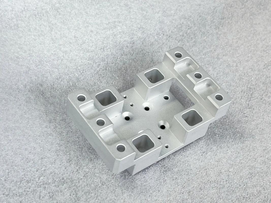
| Tooling plates and nests | Locate the workpiece or the tool | Datum grid, pin holes, pocket shape, flatness |
| Sensor, camera and changer parts | Hold devices or join two tool halves | Cable clearance, pocket depth, stack height |
Swipe the table to see all columns.
Other shapes in the same family include suction cup mount blocks, locating pins, support blocks, cable brackets, light weight frames and replacement jaw pads. The list describes machining needs. We do not hold these parts in stock. We do not publish customer project names or case studies on this page.
The Robot Wrist Interface
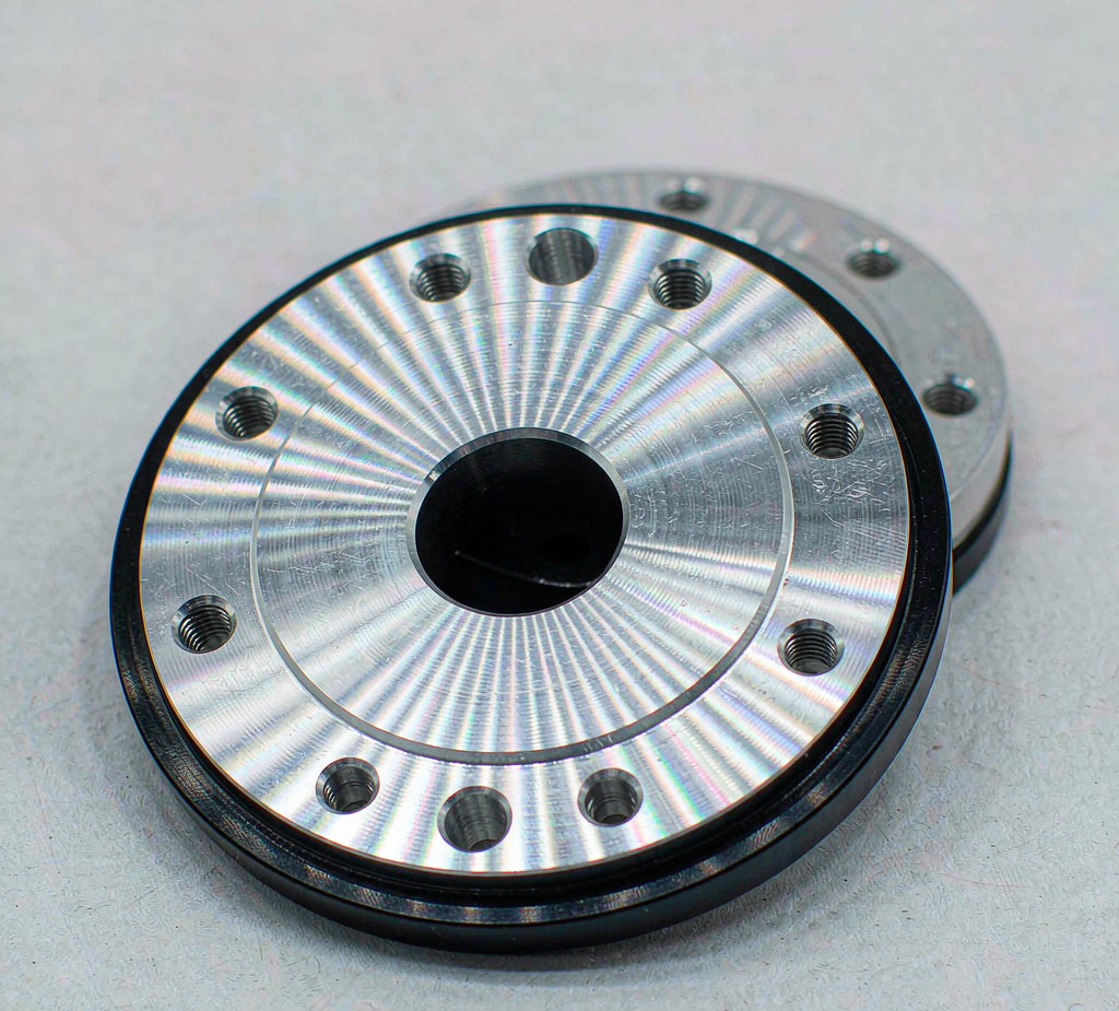
The wrist is where the tool starts. Most industrial robots use a round flange with a bolt circle, a center bore and dowel holes. The center bore locates the tool. The dowel holes stop the tool from turning. The bolt circle holds it in place. A small error in one of these three can put the whole tool out of line.
ISO 9409-1 describes a common circular mechanical interface for robot wrists. We can machine a plate to a drawing that names this standard. We still need the real bolt circle, the bore size, the dowel size and the tool side layout. We do not assume a robot size or a payload class from a standard name. We do not certify a robot system. Your drawing stays the control document.
| Interface item | Why it matters |
|---|---|
| Bolt circle and hole size | Sets whether the plate mounts at all |
| Center bore | Centers the tool on the wrist axis |
| Dowel holes | Set the angle of the tool after each change |
| Mounting face flatness | Keeps the tool from rocking under load |
| Plate thickness | Changes tool length, reach and bolt length |
| Fastener access | Decides if a wrench can reach every bolt |
| Tool side hole grid | Controls where grippers, sensors and hoses sit |
| Edge clearance | Keeps the plate clear of the arm during a move |
Swipe the table to see all columns.
Send the tool side interface drawing with the robot maker and model. If a mating part exists, send its drawing too. We then check the hole positions against one datum. We also check the plate thickness against the bolt length. A plate can be flat and still fail if the fastener cannot reach the thread.
Gripper Fingers and Contact Geometry
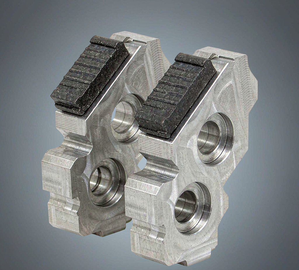
A gripper finger is a small part with a hard job. It must hold the workpiece in the same place every cycle. It must not mark a finished surface. It must also clear the fixture when the jaws open. The contact face does most of that work. Its shape comes from the workpiece, not from a standard finger size.
| Contact shape | Where it is used | What we check |
|---|---|---|
| Flat face | Square or flat sided parts | Face flatness and parallel alignment |
| Stepped face | Parts with a shoulder or a flange | Step height and seat position |
| V groove | Round shafts and tubes | Groove angle and center line |
| Curved face | Round or shaped workpieces | Profile against the 3D model |
| Soft pad seat | Finished or easy to mark surfaces | Pad pocket depth and pad fit |
| Serrated face | Rough cast or oily parts | Tooth form and edge breaks |
Swipe the table to see all columns.
We ask four questions before cutting a finger. What does the workpiece weigh? Which surface may be touched? How far do the jaws travel? Where is the fixture when the jaws open? The answers set the finger length, the pad material and the corner radii. Small radii also stop sharp edges from cutting a glove or a soft part.
Contact face named only as "hold part"
Workpiece shape, grip points and allowed contact area
Pad material left open
Pad grade, pad thickness and how it is fixed
Matched Jaw Sets and Repeat Fit
Two fingers that work together are one assembly, not two separate orders. If the left jaw and the right jaw are cut against different datums, the pair can meet at an angle. The workpiece then sits off center. We plan a matched set against one datum and inspect the pair as a set.
| Set feature | How we control it | What the record can show |
|---|---|---|
| Mounting hole pattern | One setup or one shared datum for both jaws | Hole positions against the same datum |
| Contact face height | Cut both faces in one planned step | Height of each face to the base |
| Pad seat depth | Same tool and same offset for both jaws | Seat depth on left and right jaw |
| Closed gap | Check the pair together on a gauge | Gap at the agreed close position |
| Replacement sets | Keep the revision and setup notes | Set number and drawing revision |
Swipe the table to see all columns.
Repeat orders need the same control. If you plan to order a second set next year, tell us at the first enquiry. We keep the drawing revision, the fixture notes and the check plan under one order reference. That makes the next set comparable. It does not mean we hold finished jaws in stock.
Vacuum Manifolds and Air Passages
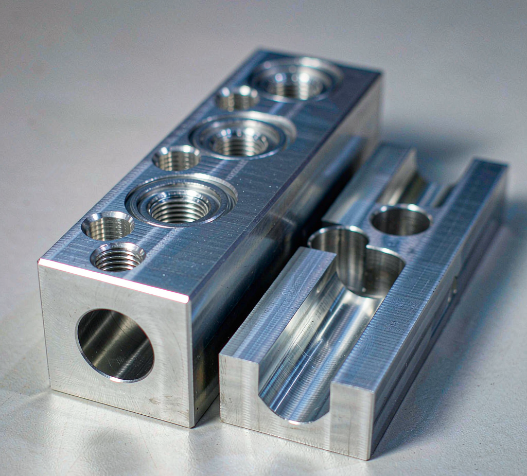
A vacuum manifold block feeds air from one inlet to several cups or pads. The outside of the block is easy. The inside is the hard part. Cross drilled holes must meet. Threads must seal. Seal faces must be flat. Loose burrs must not stay inside a passage, because they can reach a valve or a cup later.
| Feature | Machining risk | Control we plan |
|---|---|---|
| Port threads | Wrong form or a shallow thread | Named standard, gauge and thread depth |
| O-ring groove | Seal sits too high or too low | Groove width, depth and surface |
| Cross drilled passage | Holes miss each other inside | Drill order, depth and intersection check |
| Plug position | Plug blocks a side passage | Plug depth marked on the drawing |
| Internal burrs | Burr breaks loose in service | Deburr access and flush cleaning step |
| Sealing face | Leak at the mating face | Flat face, edge break, no tool marks across the seal |
| Mounting holes | Block sits out of line on the tool | One datum for ports and holes |
Swipe the table to see all columns.
We ask for the thread standard and the gauge on the drawing. We also ask where each passage ends and which ports are plugged. If you need a leak test, tell us at enquiry. A test needs a method, a pressure and an acceptance rule. We do not add a test result to a quote that has no test defined.
What a machined block does not include
- Not included: valves, pumps, cups, hoses and the vacuum control unit.
- Not included: a system level leak or safety approval for the finished tool.
- Not assumed: a working vacuum level from the grade of aluminum.
- Included when agreed: a dimensional report on the named ports, grooves and faces.
Tooling Plates, Nests and Supports
A tooling plate gives the tool a stable base. A nest gives the workpiece a known place to sit. Both parts depend on a clear datum scheme. We see two common problems. The hole grid has no datum. Or a pocket is dimensioned from a face that is machined later. Both make the assembly hard to repeat.
One reference for all holes
We ask for two datums and one origin. Pin holes, nest pockets and sensor mounts are then cut from the same reference. A grid without an origin is only a pattern.
Fit the real workpiece
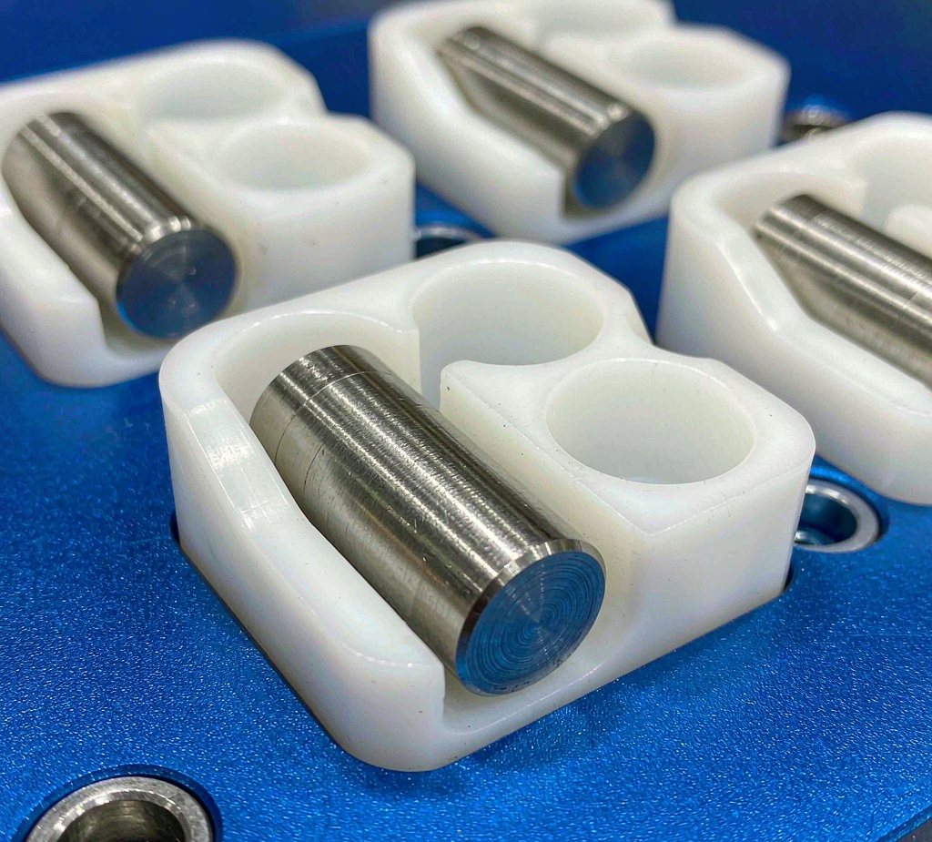
A nest pocket follows the part shape and the allowed contact area. We review draft, corner radii and how the part is released. A tight pocket can trap the part.
Protect finished surfaces
POM and UHMW-PE are used for non marking nests and pads. We agree the grade and check how it is fixed. A soft pad that moves gives the same problem as no pad.
Keep the stack true
A thin plate can bow after pocketing. We plan the cut order, the fixture support and the final skim pass. We check the mating face after the last step.
Nests, pins, support blocks and stop blocks are often ordered as one set. Send the assembly drawing when you have it. We then plan which parts are cut together and which sizes are checked together. That is cheaper than finding a mismatch after every part is finished.
Sensor, Camera and Tool Changer Parts
Modern tools carry sensors, cameras and small devices near the workpiece. Their mounts are small, but they set the view of the sensor. A bracket that is a little twisted can point a camera away from the part. A pocket that is too shallow can pinch a cable. We cut these parts against the tool datum, not against an outside edge.
| Part | What buyers need | What we plan |
|---|---|---|
| Sensor bracket | Fixed angle and cable exit | Datum face, slot length, cable radius |
| Camera mount | Stable view after a tool change | Dowel location, flat seat, stack height |
| Light bracket | Room for wires and heat | Pocket depth, clearance, edge breaks |
| Tool changer plate | Same stack height on both halves | One datum for both plates, pin fit |
| Cable guide | No sharp bend or rub point | Radii, channel width, smooth finish |
| Protective cover | Clear of moving parts | Thin wall plan, fixing holes, access |
Swipe the table to see all columns.
We do not supply the sensor, the camera or the locking unit. We make the machined parts that hold them. If you send the device drawing, we check the fixing holes and the connector space. Small parts are easy to make and easy to get wrong, so we agree the datum before the first cut.
Tool Weight, Center of Gravity and Inertia
Everything on the wrist adds load. A heavy tool can slow a move, change the stop position or push a small robot past its rated load. Weight is not only about mass. A long tool with the mass far from the wrist has a larger effect than a short tool of the same mass. This is why we ask for the workpiece weight and the tool layout early.
We do not print a fixed weight saving. We do not set a robot payload class. Those numbers come from the robot maker and from your tool design. Our job is to cut the shape you approve and to keep the walls and the mating faces sound. If we see a wall that looks too thin, we raise it before the quote.
Materials for EOAT Parts
Material choice follows the job of the part. A plate needs stiffness. A finger needs wear resistance at the contact face. A nest needs a soft surface. A washdown tool needs a grade that suits the cleaning agent. We confirm the grade and the supply papers for the lot before we order material.
| Material | Where it fits | Point to agree |
|---|---|---|
| 6061-T6 aluminum | Adapter plates, tooling plates, light brackets | Common grade, good machining, anodizing option |
| 7075-T6 aluminum | Fingers and plates that need more strength | Grade supply and the surface step |
| 304 / 316L stainless steel | Wet areas, washdown tools, wear parts | Grade, passivation and the medium it sees |
| POM | Soft jaws, nests, non marking pads | Grade, heat state, measurement conditions |
| UHMW-PE | Low friction pads and support blocks | Fixing method and how the part is held |
| PEEK | Hot areas and clean contact parts | Grade, supply papers, tool wear and cost |
Swipe the table to see all columns.
Plastics need a little more care than metal. They move with heat and some take in water. A size measured right after machining can change later. We agree the material state and the measurement conditions with you. We also use sharp tools and a controlled chip load, so the surface stays clean.
For wider material background, see our materials hub, the engineering plastic machining page and the stainless steel machining page. Those pages do not replace the drawing for your part.
CNC Routes and Setups
Most EOAT parts start as a plate, a bar or a block. We mill the outside, drill and tap the holes, cut the pockets and break the edges. Round parts go on a lathe. The route is chosen from the shape, not from a fixed machine list.
Flat plates and simple pockets
Good for adapter plates, tooling plates and brackets with features on one or two faces. We plan the order of the cuts so the plate stays flat.
Features around a part
Useful when ports or holes sit on several sides of a block. One setup keeps the hole positions tied to the same datum.
Fewer re-clamps
Useful for angled faces, curved contact geometry and deep cavities. It saves setups. It does not make every EOAT part better.
Round parts and threads
Round mounts, pins and port bosses are turned. Threads are cut or tapped to the standard named on your drawing.
A 5-axis machine is not a selling point on its own. It helps when one setup can hold the datums that would otherwise be lost. For a flat plate with a bolt circle, a 3-axis cut is often the cleaner plan. We choose the route after we see the drawing. See our 5-axis CNC machining and CNC milling services pages for the wider process background.
Every route ends with deburring and edge breaks. A sharp edge on a finger can cut a workpiece or a glove. A burr in a manifold can travel into a valve. We plan access for these steps before the block is cut, not after it is finished.
Drawing Review: What Changes the Cut Plan
A drawing review is not a sales step. It is where we find the features that will be hard to hold. We send questions, not a price, when a datum is missing or a wall is too thin. The list below is the order we follow.
Can you quote from a 3D model alone?
We can start a review from a STEP or IGES model. A price needs the 2D drawing too. The model shows shape. The drawing shows the tolerances, the datums, the thread standard and the surface step. Without those, two shops can quote two different parts.
Related: RFQ checklist
What if we have no drawing yet?
Send a photo of the old part, the mating part and the workpiece. Add the robot model and the wrist details. We can give a first view on the shape and the likely cut plan. We do not issue a final price from a photo.
Related: robot wrist interface
Datums, GD&T and Critical Features
Not every size on a drawing needs the same care. The sizes that control fit, sealing and alignment do. We call these critical features. We agree them in writing before the first cut, along with the datum they belong to and the way they will be measured.
| Feature | Typical datum | Check we can plan |
|---|---|---|
| Bolt circle position | Center bore and mounting face | Hole position to the bore axis |
| Dowel hole fit | Mounting face | Hole size and pin gauge |
| Mounting face flatness | The face itself | Flatness check on the agreed surface |
| Jaw contact face height | Jaw base and one side face | Height of both jaws from one datum |
| Pad seat depth | Contact face | Depth and pad fit |
| Manifold seal face | Port axis | Face flatness and surface condition |
| Nest pocket position | Plate datum grid | Pocket position to two datums |
| Tool changer stack height | Mounting face | Height of both plates as a pair |
Swipe the table to see all columns.
If a drawing uses GD&T, send the datum scheme with it. A position callout without a datum is hard to check. We do not replace a callout with a general tolerance note. We ask for the missing datum, then plan the measurement. This is also where we decide which features need a CMM check and which need a simple gauge.
Inspection and Records
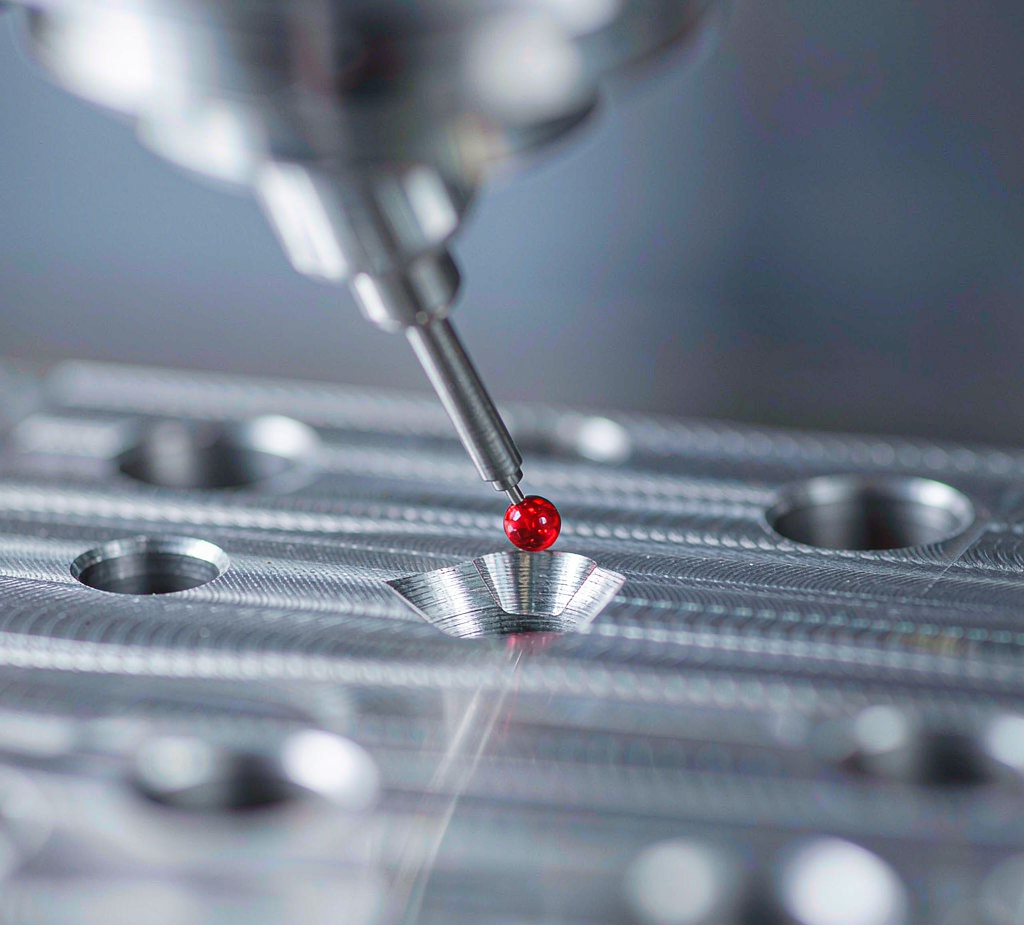
Inspection should match the risk of the part. A wrist adapter plate needs its bolt circle and bore checked. A matched jaw set needs the pair checked together. A manifold needs its threads and seal faces checked. We agree the list of sizes before the first cut, so the record matches what the drawing calls critical.
Sizes on the agreed list
We record the named critical sizes. Ask for the report format at enquiry so the file fits your system.
One part before a batch
Useful when a new tool goes into repeat supply. We agree the sample, the report and the hold point first.
For position and profile
Planned for the features that need it. We do not say that every feature on every part gets a CMM check.
For the lot we buy
Available when the order names them. We confirm the grade and the papers before material is ordered.
We do not publish customer reports, named equipment brands or process capability numbers on this page. A report belongs to the order that produced it. If you need a first article, a material paper or a special gauge, put it in the enquiry. We then build the step into the plan and the price.
Finishes, Edge Breaks and Cleaning
A surface step can change a fit. Anodizing adds a thin layer. Passivation can change a bore by a small amount. A coating can fill a pad seat. We agree the treatment, the masked areas and the re-check before we cut. This matters most on dowel holes, pin fits and sealing faces.
| Finish | Why buyers ask for it | What we agree first |
|---|---|---|
| Clear or black anodizing | Wear, look and a stable surface | Type, color, masked holes, re-check after treatment |
| Hard anodizing | More wear on contact parts | Layer effect on pin fits and pad seats |
| Passivation | Clean stainless surfaces | Grade, method and post treatment sizes |
| Bead blast | Even, low glare surface | Which faces are blasted and which are masked |
| Edge breaks | Safe handling and no cut gloves | Radius or chamfer size on the drawing |
| Internal cleaning | Clean air passages | Flush access, drying and plug plan |
Swipe the table to see all columns.
Deburring is a planned step, not a promise that a part has no burrs anywhere. We give internal passages a way to be reached and flushed. We break edges where a hand or a soft workpiece can touch them. If your order needs a written cleanliness rule, send it with the drawing.
From One Sample to Repeat Orders
Most EOAT work starts small. One sample lets you check the fit on the real wrist. A small batch then proves the process. Repeat orders come after the tool is in service. We keep the same drawing revision, the same setup notes and the same check plan under one order reference.
Check the fit first
One part shows whether the interface, the contact face and the stack height work on the tool.
Prove the setup
We check that the fixture, the tool path and the inspection plan hold across more than one part.
Keep the revision
We work to the revision named on the order. A change to the model starts a new review.
We do not print a fixed lead time here. The schedule depends on the drawing, the material supply, the surface step and the quantity. We agree dates after the review. We also do not claim a fixed cost reduction from a repeat order. A repeat setup is faster, but the price still follows the work in the drawing.
Drawing Confidentiality and Revision Control
EOAT drawings often show a customer tool design. We treat those files as customer information. Files are shared inside the engineering and production team for the order. An NDA can be arranged before files are exchanged. Ask for it at enquiry if your process needs one.
How we handle a revision
- Name the revision. Put the letter or number on the drawing and in the file name.
- List the change. Tell us which features moved, so the old setup is not reused by mistake.
- Confirm the effect. A moved dowel hole can change the fixture, the gauge and the report.
- Freeze before cutting. We work to the revision named on the order, not to a newer file sent by email.
We do not claim a certified data security system on this page. We do describe a simple working rule: one named revision, one order reference, one check plan. That rule prevents the most common repeat order error, which is a good part made to an old drawing.
What We Need for a Quote
The more the drawing tells us about the tool, the less we have to guess. You do not need a finished system design to ask for a price. Start with the robot interface, the workpiece and the parts you want machined. We can review the rest together.
| Item | What to send |
|---|---|
| 2D drawing | Sizes, tolerances, GD&T and the datum scheme |
| 3D model | STEP, STP or IGES |
| Robot maker and model | The exact machine the tool will mount on |
| Wrist interface | Flange standard, bolt circle, bore and tool side drawing |
| Workpiece | Size, mass, shape and surface that may be touched |
| Gripping method | Mechanical, vacuum or a mixed tool |
| Material | Grade, product form and any supply papers needed |
| Critical features | Pin holes, seal faces, contact faces and pad seats |
| Working conditions | Cycle rate, temperature, dust, coolant and cleaning agents |
| Finish | Anodizing, passivation, masking and re-check needs |
| Inspection | Gauges, CMM, first article and report format |
| Quantity | Sample, small batch and repeat volume |
Swipe the table to see all columns.
For EOAT projects, please provide the robot model, tool side interface drawing, workpiece weight and geometry, gripping method and critical dimensional requirements whenever available. If some of that is missing, send what you have. A sample part, the wrist drawing and a photo of the workpiece are enough for a first review.
Questions Buyers Ask Before an RFQ
Who makes custom EOAT parts for automation builders?
A shop that works from your drawing and the wrist interface, not a catalogue. Send the 2D drawing, the 3D model and the workpiece details. We review the holes, the contact faces, the material and the check plan. Then we quote a cut plan we can hold.
Related: scope and limits
Can a CNC shop supply a complete end effector?
Not from machining alone. A complete tool needs actuators, sensors, air control, wiring and a safety review. We make the machined mechanical parts. Your team or your integrator keeps the tool design and the system duties.
Related: six part families
Why do you ask for the robot model before quoting a plate?
Because the wrist interface is not the same on every robot. The bolt circle, the center bore and the dowel holes set the plate. A plate made to a generic round pattern will not mount. The model and the tool side drawing remove that risk.
Related: robot wrist interface
Which documents should I ask an EOAT parts supplier for?
Ask for a dimensional report on the critical sizes, thread gauge results, material papers for the lot and a first article report if the order needs one. Agree the format before the first cut. A material paper is not a system approval.
Related: inspection and records
Frequently Asked Questions
What are CNC machined robot end effector components?
They are the metal and plastic parts fixed to the wrist of a robot. Gripper fingers, jaw plates, adapter plates, tooling plates, vacuum manifold blocks, nests, brackets and sensor mounts are common examples. We make them from your drawing with CNC milling, turning, drilling and tapping. We do not supply the complete end effector. We do not build the air control system or the robot program. Each part is planned around its own fit, contact face and inspection need.
Can you make custom robot gripper fingers?
Yes. Send the 2D drawing and the 3D model. We need the shape of the workpiece, the contact face, the mounting hole pattern and the jaw travel. We review the material, the wall thickness and the pad seat before we quote. If the fingers must work as a matched pair, we plan them as one set. We can also make replaceable contact pads. We agree the datum and the check method in writing first.
Can you make robot wrist adapter plates?
Yes, when you send the tool-side interface drawing. An adapter plate needs the bolt circle, the center bore, the dowel holes and a flat mounting face. We ask for the robot maker, the model and the tool side drawing. We check the plate thickness and the fastener access. We do not infer a payload class from a plate drawing. We do not claim that our part replaces a named robot maker part.
Which materials work best for EOAT parts?
There is no single best material. 6061-T6 aluminum suits many light plates and fingers. 7075-T6 suits parts that need more strength. 304 and 316L stainless steel suit wet or washdown areas. POM and UHMW-PE suit soft contact faces that must not mark the workpiece. PEEK suits parts that need heat resistance. We confirm the grade and the supply papers for the lot before we order material.
Can you machine lightweight gripper parts?
Yes. We mill pockets, thin walls and ribs where the drawing allows them. Weight is not the only target. A thin wall can bend under grip force. We review the shape, the load path and the fixture support with your engineer. We do not print a fixed weight saving number. If you have a target mass, send it with the model. We check the stiffness before we agree to a cut plan.
Do you support ISO 9409-1 robot interface plates?
ISO 9409-1 describes a common circular mechanical interface at the robot wrist. We can machine a plate to a drawing that names this interface. We still need the bolt circle, the center bore, the dowel holes and the tool side details. We do not assume a robot size or a payload class from the standard name. We do not certify a complete robot system. Your drawing stays the control document.
Can you machine vacuum manifold blocks?
Yes. We mill the block, drill the air passages, cut the port threads and machine the seal faces. Cross holes must meet inside the part without loose burrs. We plan the plug positions and the access for cleaning. We check the threads with the gauge named on your drawing. A leak test is only planned when your order defines the method, the pressure and the acceptance rule.
What tolerances can you hold on EOAT parts?
Key sizes follow your drawing. We do not print one blanket number for every bore, pin hole and contact face. A tight feature is reviewed before we accept it. We agree the feature, the datum and the measurement method in writing before we quote. That is more useful than a single number on a web page. We also note which sizes can change after anodizing or another surface step.
How do you inspect matched gripper fingers?
We check the pair together. The contact faces, the pad seats and the pin holes must line up when the jaws close. We set one datum for both parts. We can plan a dimensional report, a first article inspection and a CMM check on the agreed features. Tell us what the record must show before the first cut. We do not say that every feature on every part gets a CMM check.
Can you machine POM or PEEK gripper jaws?
Yes, when the drawing calls for the grade. POM and PEEK are used where a soft, clean contact face is needed. They move with heat and can take in water, so we agree the material state and the measurement conditions. We use sharp tools and control the chip load. We confirm the grade and the supply papers for the lot. Tell us if the part touches a food or medical surface.
Can you support prototypes and repeat batches?
Yes. We can start with one sample part, then move to a small batch and to repeat orders. The first sample is a chance to check the fit before more parts are cut. We keep the drawing revision, the setup notes and the inspection plan under one order reference. We do not print a fixed lead time here. We agree the schedule after we see the drawing, the material and the quantity.
What do you need for an EOAT quote?
Send the 2D drawing and the 3D model. Add the robot maker and model, the tool side interface drawing, the workpiece size and weight, the gripping method and the material. Mark the critical features and the quantity. Add the working conditions, the finish and the inspection record you need. If you have no drawing yet, send a sample part and the mating details. We start with a drawing review.
Related Capability Pages
This page covers one part family. The pages below cover the wider process, material and precision background.
Discuss Your Custom EOAT Project
Send the 2D drawing, 3D model, robot wrist interface, workpiece details, material and critical features. Our engineers review the holes, the contact faces, the air passages, the weight and the inspection plan. Then we quote a process we can hold.
Drawings are handled under our standard confidentiality procedure. An NDA can be arranged before files are exchanged.