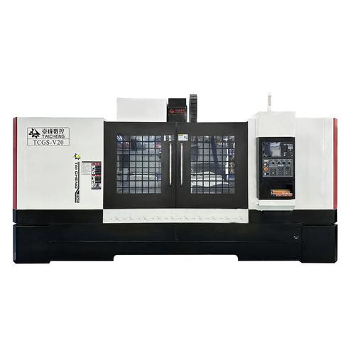
Custom Injection Molding for Consumer Electronics Housings
Developing a consumer electronics housing? Goldcattle supports OEM/ODM injection molding of enclosures and shells — from assembly-interface design review and material selection through tooling, sampling and volume production.
In consumer electronics the housing is an assembly component, not just a cover: it locates the PCB, carries buttons and connector openings, closes with a defined feel, and presents the product's most visible surface. We review geometry, material options, surface requirements and moulding risks before tooling decisions are finalized, so the cosmetic and assembly interfaces are engineered rather than discovered at first trial.
This page is a working reference. The RFQ checklist at the end is shown in full — select the text to reuse it, or use your browser's print / save-as-PDF. Goldcattle does not host downloadable files on this site.
01 · Consumer Electronics Housings We Mold
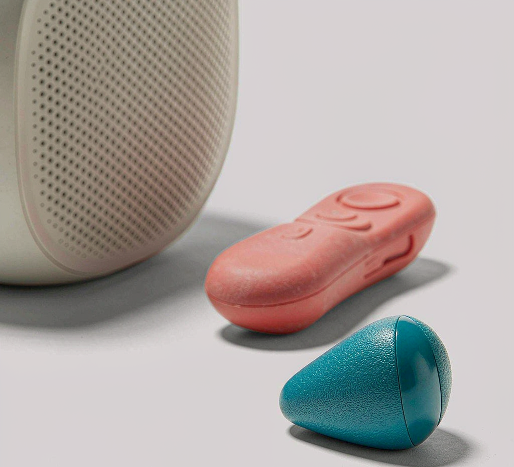
We mold enclosures and shells for consumer electronic products, grouped below by device family. What varies between them is not the resin but the engineering emphasis: drop survival for handheld devices, visible-surface quality for living-room products, and sealing or chemical resistance for kitchen and bathroom devices.
Handheld & remote devices
Remote controls, handheld meters and portable device shells where drop impact, button feel and thin-wall light-coloured sections drive the design.
Smart speakers & IoT devices
Living-room and desk devices where the visible face carries the brand: grille acoustics, fabric or texture interaction, and consistent colour across batches.
Control panels & HMI enclosures
Operator panels and interface enclosures with membrane or rubber keypads, display windows and frequent assembly access.
Set-top boxes & networking equipment
Ventilation-driven enclosures where thermal design, connector access and cable routing shape the split line and rib layout.
Wearables & portable devices
Small enclosures with fine detail, TPE overmould grip zones and sealing targets reviewed against the device's real use environment.
Instrument & meter enclosures
Measurement and display instruments where window clarity, dimensional stability and repeated service access matter.
How this page differs from our housing product page
Our custom injection-molded plastic housing page gives a capability overview across industries. This page goes deeper on the consumer-electronics side specifically: assembly interfaces, material and compliance boundaries, appearance control and the tooling-to-production sequence for devices that ship in volume.
02 · Assembly-Interface DFM for Electronics Housings
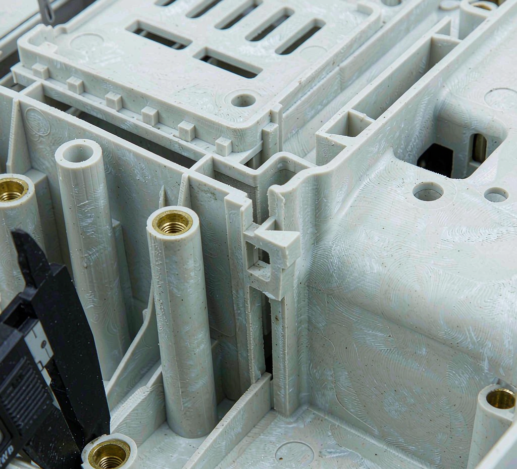
A consumer electronics housing is reviewed interface by interface — how the PCB mounts, how cables pass, how buttons actuate, how the shells split and close, and how the display sits. Each interface below is a design review item with its own failure risk, evaluated against your internal assembly before tooling.
| Interface | What the design review establishes | Risk if missed |
|---|---|---|
| PCB mounting bosses | Boss diameter, wall and rib support set from screw size and tightening load; axes kept clear of knit and weld lines | Stripped or cracked bosses, sink marks, PCB stressed at assembly |
| Connectors & cable routing | Opening position and tolerance against the connector and mating cable; internal routing channels and strain relief | Connector interference, cables pinched at assembly, rework |
| Buttons & keypads | Actuation gap, travel and feel; sealing land where a rubber keypad or membrane is used | Stiff or dead keys, light leakage, water ingress at key openings |
| Top / bottom shell split | Split-line position on visible faces, tongue-and-groove or land design, screw or snap closure strategy | Visible step or flash on the cosmetic face, poor closure feel, assembly mismatch |
| Display & optical windows | Window recess, support rib layout and adhesive land; gate and knit lines kept off the viewing area | Warped or stressed window, visible flow marks, adhesive gaps |
| Thermal & ventilation | Vent slot geometry and placement against the thermal design; rib layout that leaves airflow paths open | Hot spots, forced over-thick walls, blocked airflow from added ribs |
| Sealing & gasket lands | Continuous groove or land geometry, compression set from the gasket spec, parting-line control at the seal | Leak paths at corners and split line; sealing that passes a sample and fails in service |
The fastest route through this review is a PCB layout or stack-up drawing alongside the CAD — it lets boss, opening and split-line positions be checked against the real assembly rather than the shell alone.
03 · Material Selection and the UL94 Boundary
Housing materials are screened from impact, appearance, regulatory and cost requirements together — not from a single headline property. The table below is a starting direction; the grade is confirmed per project against your product's drop, touch, colour and compliance requirements.
| Material direction | Typical evaluation fit | Limits and factors to confirm |
|---|---|---|
| ABS | Rigid indoor housings, paintable shells, cost-driven volume products | Impact and temperature limits, UV stability for lit or outdoor-adjacent products, grade-specific behaviour |
| PC | Impact-critical or transparent windows and covers; thin light-coloured sections | Chemical compatibility (cleaning agents, sunscreens), stress cracking, moulded-in stress from processing |
| PC-ABS blend | Housings balancing impact, flow and surface quality — common in handheld and living-room devices | Impact vs flow trade-off by grade, temperature and chemical exposure, colour match |
| Flame-retardant grades (ABS / PC / PC-ABS FR) | Applications where a flammability requirement is specified for the enclosure | Flammability is a material-level property — see the UL94 boundary below; property retention and colour confirmed by grade |
| TPE / TPU overmould | Grip zones, seals, bumpers and soft-touch areas bonded to a rigid substrate | Adhesion to substrate, overmould tooling and cycle, compression set where used as a seal |
The UL94 boundary — read this before specifying V-0
UL94 is a material-level flammability test: a resin specimen of a defined thickness is rated (V-0, V-2, HB and others) under the standard's conditions. A UL94 rating on the resin is not an end-product fire certification, and a V-0 resin does not by itself make the finished device certified — product-level certification is a separate assessment of the complete device. Where a flammability requirement exists, we confirm the resin's rating against the specified rating, thickness and grade, and the end-product requirement stays with your product certification scope.
Grade-level detail sits in the materials section. RoHS and REACH obligations follow the substances in the materials and parts used — declarations are confirmed per material and per project, against your market and customer requirements.
04 · Structural DFM for Housings and Shells
Housing DFM is about how the shell survives assembly, drop and daily handling — and how it closes and re-opens if serviced. Each item below is reviewed on the actual geometry, because the same feature that passes on a small remote can fail on a large panel.
| Engineering question | What the design review establishes |
|---|---|
| Wall thickness & uniformity | Nominal wall and transitions: thick-to-thin transitions create sink, warp and long cycles; uniformity is designed in, not corrected at trial |
| Ribs & standoffs | Stiffness and PCB support added without thick sections; rib thickness kept proportional to the wall it serves to avoid sink and stress lines |
| Screw bosses & inserts | Boss geometry for self-tapping screws or brass inserts, with surrounding support against tightening load and repeated service |
| Snap-fits | Cantilever geometry, deflection during assembly and retention force; hooks reviewed for mouldability and stress at the root |
| Parting line & knit lines | Split-line position on visible faces, and weld-line placement away from load-bearing or cosmetic regions |
| Tolerance stack on interfaces | Boss positions, window recess and connector openings checked against the internal assembly stack, not nominal-to-nominal |
Mould and production controls that protect the design
- Gate location — kept off visible faces and away from critical weld-line regions; flow direction reviewed against the part's cosmetic and functional surfaces.
- Weld-line management — placement reviewed against boss and window areas so the lines land where they neither weaken nor show.
- Cooling balance — uniform heat extraction on large flat shells, where imbalance shows up as warp and dimensional drift.
- Colour masterbatch control — colour let-down ratio and batch verification agreed before production, so shell colour holds across batches and matched parts.
- Cavity consistency — cavity count is a cost and consistency decision, balanced per project against volume and cosmetic tolerance.
- Ejector &> vent placement — marks kept off cosmetic faces; venting reviewed to avoid burn marks on deep or ribbed sections.
Tool design, steel selection and trial stages are covered on the injection mold making page; baseline process and DFM practice is described on the injection molding services page.
05 · Appearance and Surface Quality
For most consumer products the housing is the brand surface, so appearance is specified like a dimension — agreed before tooling and verified per batch. The items below are the appearance checklist we work through with buyers who ship visible products.
- Colour and gloss specification — target colour and gloss level agreed with reference samples, with batch-to-batch tolerance defined before production rather than judged at delivery.
- Texture — moulded texture specified by standard reference and depth; texture affects both look and how scratches and flow marks show on a glossy surface.
- Parting-line visibility — split-line position reviewed against the product's visible faces and how the shell is held in use.
- Gate, ejector and weld marks — placement reviewed so process marks stay off cosmetic areas; where a mark is unavoidable, it is identified at DFM.
- Secondary finishes — painting, UV coating and silk screening reviewed for coverage, adhesion and registration on the specified substrate.
- Boundary samples — an agreed appearance boundary sample set before volume production, so "acceptable" is a reference part rather than an opinion at the dock.
Appearance defects that pass a functional inspection — slight gloss mismatch, texture depth variation, ejector witness on a visible face — are the most common consumer-electronics disputes. Defining the boundary sample and the inspection conditions up front is what prevents them.
06 · Tooling, Samples and Scale-Up to Volume
The path from design to volume housing runs through defined trial stages: engineering review, tool build, trial samples, sample approval, then production. Each stage has a purpose — and the approval point is where cosmetic and dimensional acceptance is locked before volume commitment.
1 · DFM review
Assembly interfaces, wall and rib layout, gate and split-line position, material and colour direction — reviewed on your CAD before tooling.
2 · Tool design & build
Tool structure, steel, cooling and cavity count agreed against volume and cosmetic tolerance; surface texture applied per specification.
3 · Trial samples (T0 / T1)
First trial parts checked for dimensions, assembly fit and appearance; issues feed tool correction before the approval sample.
4 · Sample approval
Cosmetic boundary samples and dimensional report agreed — the reference both sides verify production against.
5 · Volume production
Process window documented, first-article inspection per batch scope, and key dimensions sampled through the run.
Before tooling exists
For design iterations before tooling, machined or 3D-printed prototype shells are an option — the CNC machining services page covers prototype-part fabrication. Prototype parts validate fit and assembly; they do not substitute for trial shots from the production tool.
07 · Quality Control and Compliance Scope
Housing quality splits into two scopes: the part is verified as manufactured (dimensions, appearance, material), and the product's regulatory claims are verified at product level. We support the first directly and provide the documentation the second depends on — the boundary between them is stated plainly below.
| Verification scope | What it covers |
|---|---|
| Dimensional inspection | Critical dimensions, boss and hole positions, window recess and assembly interfaces — gauged or measured per the agreed sampling plan |
| Appearance inspection | Colour, gloss, texture, flow marks and process marks against the agreed boundary samples and lighting conditions |
| Material verification | Specified grade and colour, material batch documentation, and required material declarations |
| Assembly fit | Closure, snap retention, button actuation and fit against the internal assembly where test fixtures are available |
| Batch documentation | First-article records, process records and traceability where the project requires them |
What is verified at product level — not at the shell
IP ratings (IP65, IP67 and similar) are test results of the assembled product, not of the moulded shell — the housing design supports a sealing target, and the rating is confirmed by testing the finished assembly. Flammability at product level, EMI / EMC performance, and any device certification are likewise product-level assessments. RoHS / REACH obligations follow the substances in the materials and parts, confirmed per material and per project against your market. None of these are claimed from the resin or the shell alone.
Dimensional verification on housings concentrates where the assembly interfaces live: boss positions, window recess, connector openings and closure features. Gauging or measurement is applied per the agreed sampling plan, and the first-article record becomes the reference for the run.
Baseline quality process — first articles, dimensional reports, in-process checks and material files — is described on the injection molding services page. This section defines what is verified on the housing itself.
08 · Engineering Review: Smart-Home Control Panel Housing
A representative programme type from our consumer-electronics moulding work — anonymised, with no customer names, part numbers or measured performance figures published. The value of the example is the review sequence: assembly first, cosmetics second, tooling last.
| Review item | Detail |
|---|---|
| Application | Wall-mounted control panel for a smart-home device — visible face, membrane keypad, display window, rear electronics cavity |
| Design objective | One-shot shell carrying the PCB, keypad and window, closing onto a rear cover with a defined service access |
| Key engineering risks | Visible-face flow marks and gloss variation; boss axes crossing knit lines; window area warp under adhesive; split-line visibility on the mounted face |
| DFM considerations | Gate position set to keep weld lines off boss and window regions; wall and rib layout balanced for uniform gloss; window support ribs designed for adhesive land without stress on the viewing area; split line placed on the least visible edge; texture specified with gloss tolerance against boundary samples |
| Tooling & production | Cavity count and texture agreed against volume; colour let-down and batch verification documented; ejector marks kept off the visible face |
| Validation focus | First-article dimensional report on boss and window positions; closure and keypad fit checked against the assembly; cosmetic boundary samples agreed before volume |
| Outcome | A housing that met the assembly and cosmetic specification, produced in the same tool across repeat orders with batch colour control documented |
On the evidence
No measured performance figures are published for this programme — dimensional data, test results and customer details are shared under NDA during a project evaluation. The value of the example is the problem → judgement → manufacturing → validation sequence, not a result number.
09 · Consumer Electronics Housing RFQ Checklist
A housing inquiry becomes an evaluable project when it carries the eight items below. You do not need all of them to start — a CAD model plus a description of the internal assembly is enough to begin the review, and the DFM stage identifies what else is needed.
| # | Information | What it drives |
|---|---|---|
| 1 | 3D CAD and 2D drawing | Geometry, wall sections and moulding assessment |
| 2 | PCB / internal assembly interface | Boss, opening and split-line positions against the real stack |
| 3 | Material and colour preferences | Grade direction, colour matching and compliance screening |
| 4 | Surface finish & texture requirements | Tool texture, secondary finishing and appearance specification |
| 5 | Quantities — first batch, annual, lifecycle | Tool structure, cavity count and batch economics |
| 6 | Closure method — screws, snaps, service access | Boss and snap design, tool actions and assembly strategy |
| 7 | Compliance targets — flammability, sealing, declarations | Material screening and which claims are verified at product level |
| 8 | Timeline and sample expectations | Trial stages, approval sequence and schedule planning |
Quantities, schedule and commercial terms are confirmed in the quotation after the design review — no generic ranges are published here, because tool structure and validation scope move them per project.
10 · Frequently Asked Questions
What is consumer electronics housing injection molding?
It is the production of protective enclosures and shells for electronic devices by injecting molten resin into precision tooling. In consumer electronics the housing also carries the assembly — PCB mounting bosses, snap-fit closures, button and connector openings and cosmetic surfaces — so the moulding decision affects both assembly cost and product appearance.
Which plastic is best for consumer electronics housings?
It depends on the product's requirements. ABS is common for rigid, paintable indoor housings; PC and PC-ABS blends add impact resistance and are used where drop survival or thin-wall light-coloured sections matter; flame-retardant grades are selected where the application calls for them. The grade is confirmed per project against impact, appearance, regulatory and cost requirements.
What does UL94 V-0 mean for a plastic housing?
UL94 is a material-level flammability test: it rates a resin at a specified thickness, and V-0 means the specimen self-extinguishes within defined limits. A UL94 rating on the resin is not an end-product fire certification — product-level certification is a separate assessment on the finished device.
Can injection-molded housings be sealed to IP65 or IP67?
The housing design can be built to support a sealing target — continuous seal groove, even land compression, controlled parting line — but an IP rating is a test result of the assembled product, not of the moulded shell. Any IP rating is confirmed by testing the finished assembly under the applicable standard.
How are PCBs mounted inside a molded housing?
Through moulded bosses with self-tapping screws or brass inserts, positioned so the screw axis stays clear of knit lines and weld lines. Boss diameter, wall thickness and surrounding rib support are set from the screw size, tightening load and assembly access — and reviewed at DFM before tooling.
What surface finishes are available for consumer electronics housings?
Common options include moulded texture, matte or gloss as moulded, painting, UV coating and silk screening. Texture and gloss level affect both appearance and scratch visibility, so the finish specification is agreed with the material and colour before tooling — the options are confirmed per project.
What is the minimum order quantity and lead time for consumer electronics housings?
Both are project-specific rather than fixed ranges — they follow the tool structure, material, cavity count and validation scope agreed for the part. Quantities and schedule are confirmed in the quotation after the design review, and prototypes before tooling are discussed separately from production.
What information is needed for a consumer electronics housing quote?
3D CAD and 2D drawing, the PCB or internal assembly interface, material and colour preferences, surface finish requirements, expected volumes and any regulatory or compliance targets such as flammability or sealing. A PCB layout or stack-up drawing helps the boss and opening review.
Have a consumer electronics housing to develop?
Send your CAD model, the internal assembly interface and your appearance requirements. Goldcattle reviews the geometry, material direction, surface specification and tooling considerations against your product specification.
- Assembly interfaces reviewed before tooling decisions
- Appearance and colour specified against boundary samples
- Compliance scope stated plainly — shell, material and product level

Reviews assembly-interface DFM, material selection and appearance specifications for consumer-electronics housings. Goldcattle has manufactured custom plastic and metal parts since 1998 under an ISO 9001:2015 quality system.