Custom CNC Power Tool Housings and Gearcase Components
Aluminum and magnesium gearcase machining, die-cast post-machining, precision bearing bores and motor interfaces for power tool OEMs, with plastic outer shell coordination through injection molding.
At a glance
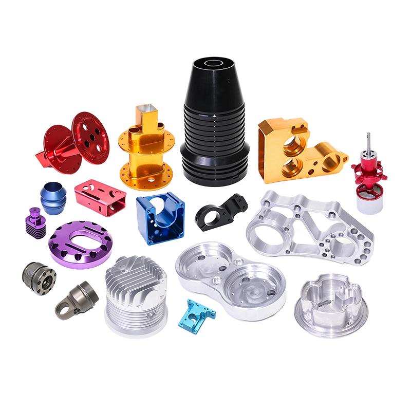
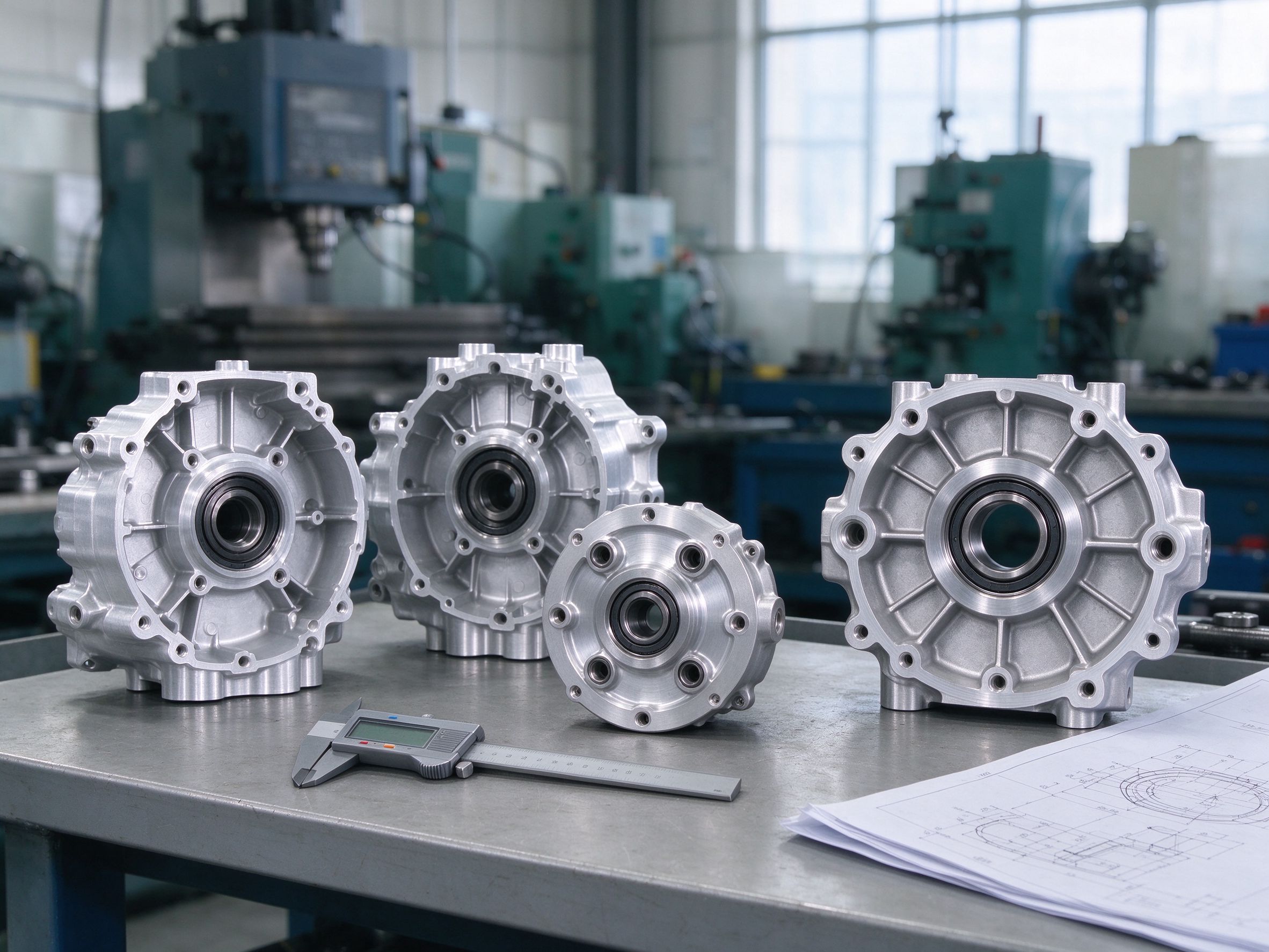
Goldcattle supplies custom metal gearcase and motor housing components for power tool OEMs from engineering drawings. The metal group covers split gearcase bodies, motor end housings, bearing supports, gearbox covers, spindle housings and mounting plates. These parts carry bearing bores, gear shaft positions, motor mounting faces, sealing interfaces and fastener bosses. Plastic outer shells and grips are a separate injection-molding route. Metal housings can be CNC machined from billet for prototypes and low volumes, or die cast near-net-shape and finish-machined in CNC. Route, material and tolerance are confirmed after drawing and assembly review, not assumed from the keyword alone.
What a Power Tool Housing Must Do Inside the Tool
A handheld power tool separates into two housing groups that buyers should not mix in one quotation. The metal gearcase and motor housing is the structural load path: it locates the bearings, holds the gear shafts at their designed center distance, seats the motor, and provides the split faces, bosses and fasteners that hold the assembly together. The plastic outer shell and grip provides external form, hand contact and isolation, and is normally produced by injection molding rather than CNC cutting.
The metal group is where alignment, rigidity and sealing matter. A bore that drifts position changes gear mesh; a mating face that is not flat affects split-line sealing; a boss that fails under repeated assembly loosens the cover. This page focuses on those metal functional housings and the matching precision components, with the plastic shell covered as a coordinated manufacturing capability rather than a second product catalog.
Goldcattle has manufactured metal and plastic components since 1998 and works under an ISO 9001:2015 quality system. Related capability pages cover precision CNC machining services, custom aluminum and magnesium die casting, custom plastic injection molding, and integrated metal and plastic manufacturing under one BOM and tolerance review.
Power Tool Housings and Components We Manufacture
The component list below follows function inside the gear train and motor interface, not a generic enclosure category. Each family is reviewed against the assembly drawing, bearing arrangement and required fit.
Gearcase Housings
Split or single-body metal cases that enclose the gear train, carry bearing bores, gear shaft positions and split-line mating faces, and connect to the motor side.
Motor End Housings
End covers and stator-side housings that locate the motor, provide the mounting face and hole pattern, and close the gearcase at the motor interface.
Bearing Supports
Bearing seats and carrier structures that hold the bearing outer ring, transfer load into the housing wall or rib, and keep the shaft axis aligned with the gear train.
Gearbox Covers
Removable side and end covers with sealing faces, fastener bosses and access features, machined to match the mating housing split line.
Spindle Housings
Housings around the output spindle or quill, carrying the output bearing seat, drive interface and mounting geometry for the tool head.
Motor Mounts
Mounting brackets and interface plates that fix the motor to the gearcase, with hole positions, locating features and load-bearing bosses.
Bearing Carriers
Rotational or plate-type carriers that position one or more bearings, often produced by turning combined with milling and drilling.
Mounting Plates
Interface plates and flanges that connect the housing to adjacent assemblies, with drilled hole patterns, dowel locations and flat mating surfaces.
Power Tool Applications
Metal housing requirements vary by tool type because the gear train, motor load and grip layout differ. The descriptions below cover the housing structure, not the finished tool.
Cordless Drills
Drill gearcases carry the drill gear train, motor seat and chuck-side output bearing. Bore alignment and split-face flatness control gear mesh and cover fit under repeated tightening.
Impact Wrenches and Drivers
Impact tool housings must hold the drive shaft and bearings against torque reaction, with rigid bosses and ribs around the bearing seat and fastener locations.
Angle Grinders
Grinder gearcases connect the motor axis to the output spindle through an angled gear pair, so shaft center distance, bore position and mating face flatness are reviewed against the bevel gear arrangement.
Rotary Hammers
Rotary hammer housings combine gear reduction with impact mechanisms; bearing supports and bosses are sized for vibration and impact loads specified on the assembly drawing.
Manufacturing Route Selection: CNC Billet, Die Casting or Injection Molding
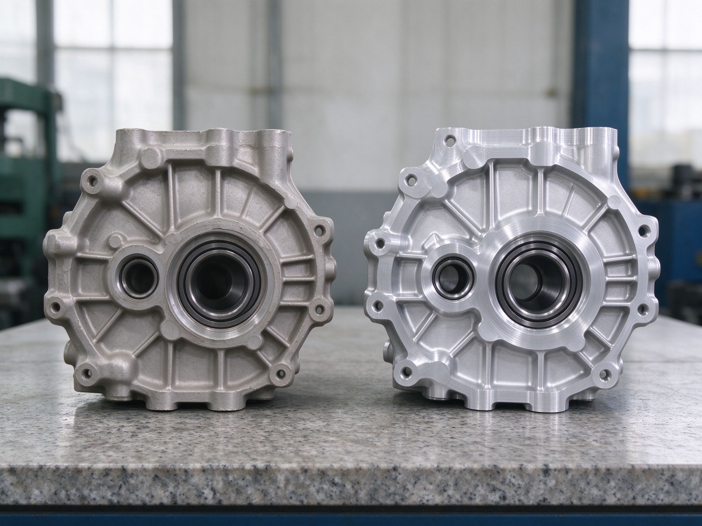
Not every power tool housing should be CNC cut from solid stock. The route follows design maturity, geometry, annual volume and target cost. CNC machining covers billet parts and finish work; die casting forms near-net metal structures; injection molding produces the plastic shell and grip. The manufacturing services overview lists the combined capability base.
| Evaluation factor | CNC billet machining | Die casting plus CNC | Injection molding |
|---|---|---|---|
| Design change frequency | Suits frequent revisions; no forming die to modify | Geometry should be stable before die investment | Geometry should be stable before mold investment |
| Initial tooling | No forming die; fixture and programming required | Die casting die plus CNC fixtures | Injection mold plus any metal inserts |
| Complex ribs and features | Limited by tool reach and cutter access | Near-net ribs, walls and bosses in the casting | Complex plastic ribs and undercuts in the molded part |
| Critical bores and mating faces | Machined directly to final tolerance | CNC finishes bores, faces and threads after casting | Uses molded control, inserts or post-machining where required |
| High-volume economy | Material removal limits per-piece cost at volume | Usually more favorable for stable metal production | Usually more favorable for stable plastic production |
| Typical object | Metal prototypes and low-volume housings | Production metal gearcases and end housings | Plastic outer shells, grips and covers |
Materials for Metal Housings and Plastic Shells
Metal and plastic selection follows different logic. The metal housing is chosen for rigidity, weight, load path and machining or casting behavior; the plastic shell is chosen for impact, appearance, grip and molding behavior. The grade is confirmed against the operating condition, not copied from another tool model.
| Part group | Material candidates | Selection focus |
|---|---|---|
| Metal gearcase | Aluminum die-cast alloys | Structural rigidity, weight balance and available machining allowance on casting features |
| Lightweight metal housing | Magnesium AZ91D, AM60B | Weight reduction and impact behavior; corrosion condition reviewed against exposure environment |
| CNC prototype housing | Aluminum 6061-T6 | Prototype development, machinability and readily available billet |
| High-strength CNC part | Aluminum 7075-T6 | Higher strength requirement where the environment and cost support the grade |
| Bearing support insert | Steel, stainless steel | Hardness, bearing fit and wear resistance at the contact surface |
| Plastic outer shell | ABS, PC/ABS | Impact resistance, appearance and molding behavior |
| Reinforced tool body | PA6, PA66 with glass fiber | Strength and stiffness; moisture and dimensional change considered in design |
| Grip and soft touch | TPE, TPU | Hand contact, wear and bonding or overmolding arrangement |
Critical Engineering Requirements for Gearcase Housings
The nine requirements below are the features a power tool OEM typically audits on a metal housing. They describe what must be defined on the drawing and what the supplier checks; each project sets its own acceptance values.
Bearing Bore Accuracy
Bore diameter, roundness, seat surface condition and the fit against the bearing outer ring. A bore that runs loose or off-center affects shaft position and bearing life.
Gear Shaft Alignment
Shaft center distance, bearing bore position, coaxiality and runout between axes, checked against the gear pair and backlash requirement.
Motor Mounting Geometry
Stator seat, mounting face, hole pattern, concentricity and axial position that sets rotor clearance relative to the gear train.
Mating Face Flatness and Sealing
Split-line flatness, gasket or O-ring groove geometry, contact width and fastener location that hold grease and keep dust out of the gearcase.
Fastener Boss Integrity
Threaded holes, press-in inserts, screw bosses and pull-out resistance sized for repeated assembly and disassembly during service.
Thermal Management
Cooling fins, vent openings and material heat transfer around the motor and gear train; thermal distortion between datums is considered in the machining review.
Vibration, Impact and Torque
Rib layout, wall sections and boss support against vibration, impact and torque reaction from the tool duty cycle specified in the assembly review.
Weight and Rigidity
Balance between housing weight and structural stiffness, reviewed with rib geometry, wall sections and load paths rather than material density alone.
Finishing and Corrosion Protection
Coating choice, masking of fit surfaces, coating thickness control and corrosion protection matched to the material and exposure condition.
CNC Processes Used on Power Tool Gearcases
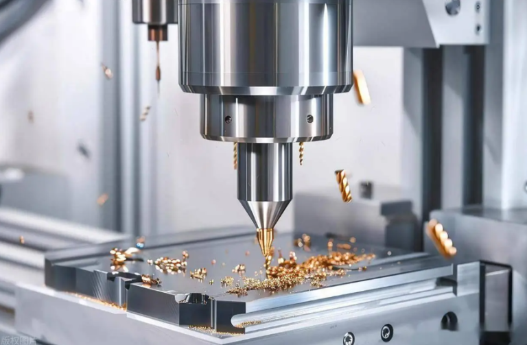
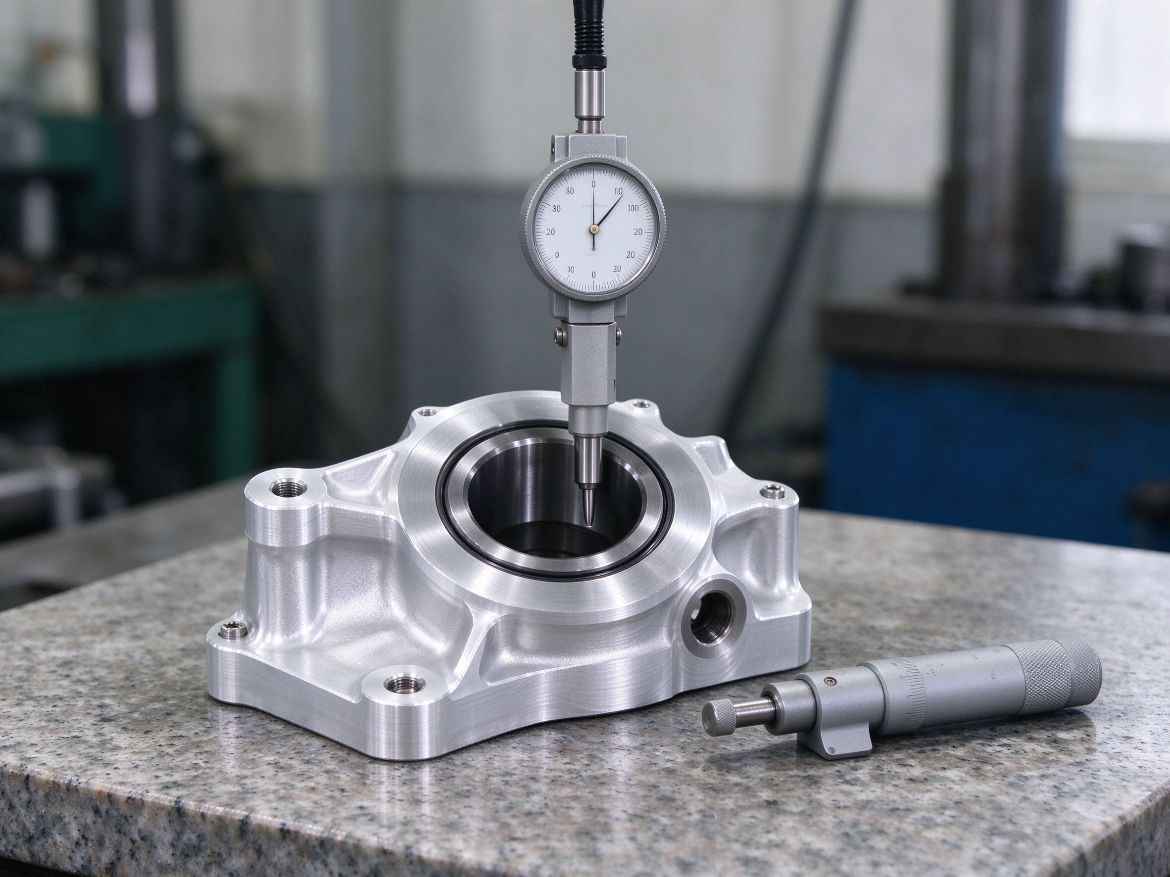
Housings are prismatic parts with rotational bearing and shaft features. The process mix follows the geometry and datum plan set after DFM review; a part does not automatically require five-axis machining.
CNC Milling
Mounting faces, pockets, ribs, flats, slots and contoured edges on the housing body, cover and mounting plate.
Boring and Reaming
Finish sizing of bearing bores and gear shaft holes, controlling diameter, roundness and seat condition against the drawing tolerance.
Drilling and Threading
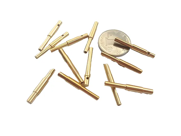
Mounting holes, boss holes, tapped threads and thread-milled features, with thread inspection where the drawing requires it.
Multi-Axis and Turning
Four- or five-axis work for multi-face access and angled features; turning for bearing carriers, spacers, adapters and other rotational components. Five-axis capacity is covered in the 5-axis CNC machining services page.
CNC Post-Machining of Die-Cast Housings
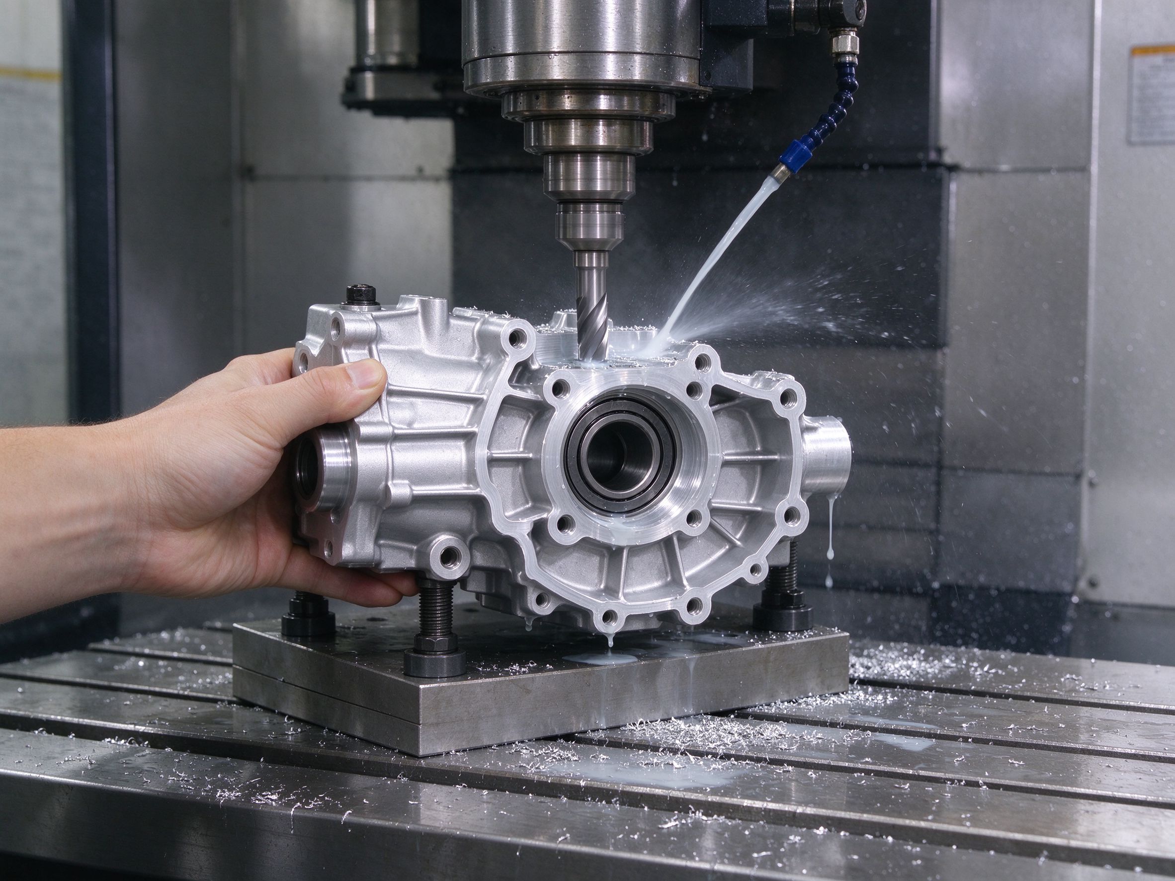
A casting is a near-net blank, not a finished gearcase. The rough casting leaves walls and ribs close to final shape, but bearing bores, mating faces, holes and threads usually need CNC finish machining to reach assembly tolerance. The sequence below follows a typical die-cast housing program; the exact steps are set against the drawing and casting allowance.
- Raw casting inspection: check the blank for defects, wall condition and leftover allowance before it enters machining.
- Datum establishment: choose and machine the reference datums that subsequent setups and measurements will use.
- Fixture design: build the holding concept around the casting features, avoiding clamping stress near bearing bores and sealing faces.
- Bearing bore machining: rough and finish the bearing seats to diameter, position and surface condition.
- Gear shaft hole machining: machine the shaft holes to center distance, coaxiality and perpendicularity requirements.
- Mating face machining: finish split faces and mounting faces to flatness and seal contact requirements.
- Threading and tapping: cut internal threads in bosses and check thread form and engagement.
- Deburring and cleaning: remove burrs from bores, threads and edges, and clean chips from internal passages.
- Surface finishing: arrange conversion coating, anodizing, painting or other finish, with fit surfaces masked or allowance protected.
- Final dimensional inspection: verify critical bores, positions, threads and faces against the inspection plan before release.
Tolerance Tiers Applied Feature by Feature
Tolerance is set on each feature according to its function. The project does not carry a blanket tight tolerance across every wall, edge and hole; general features follow the drawing, and only location-critical features move to the tighter tiers.
Per drawing
Non-critical walls, outer contours and cosmetic features follow the drawing and general tolerance block agreed at review.
±0.01 mm
Mating faces, mounting hole patterns and bearing seats that require controlled fit and position are reviewed to precision tolerances such as ±0.01 mm where the drawing calls for it.
±0.005 mm qualified
Tighter ±0.005 mm features are reviewed case by case for feasibility, measurement method and fixture stability; they are not promised on every bore or face.
Surface Finishing and Corrosion Protection
Finishing is selected for the material and the exposure condition, with fit surfaces planned ahead of coating. Bearing bores, gear mating faces and sealing grooves must either be masked or carry finish allowance, because coating thickness changes fit and seal contact.
- Aluminum: anodizing, conversion coating, powder coating or painting, chosen against appearance, wear and corrosion requirement.
- Magnesium: conversion coating or approved protective coating, reviewed for the exposure environment and compatible fastener materials.
- Steel inserts: zinc plating, black oxide or painting, with thread and bore protection arranged per part.
- Plastic parts: mold texture, painting, laser marking or other finish defined on the plastic drawing.
CNC machining, die casting and injection molding are handled in-house; some special coatings are arranged through qualified partner suppliers and managed against the project quality agreement. The in-house versus partner split is confirmed at RFQ so the buyer knows who performs each finish step.
Dimensional Inspection and Assembly Validation
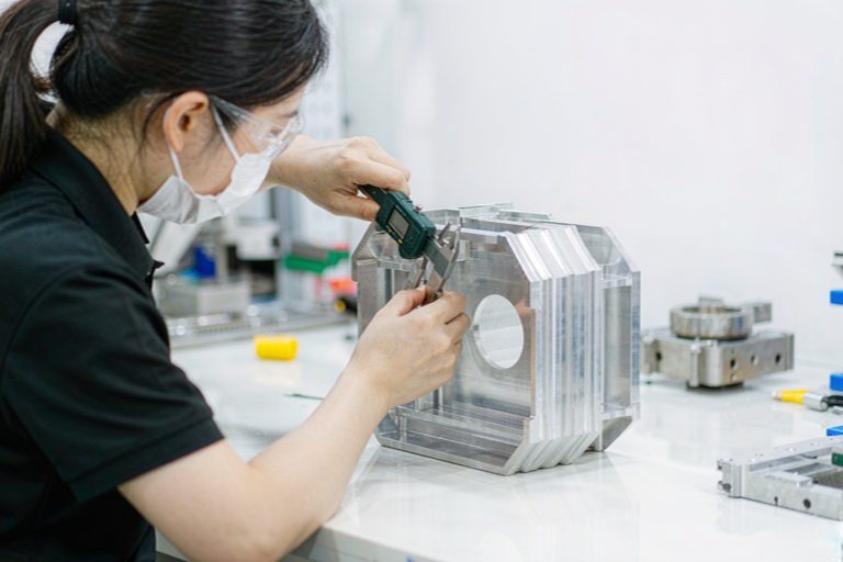
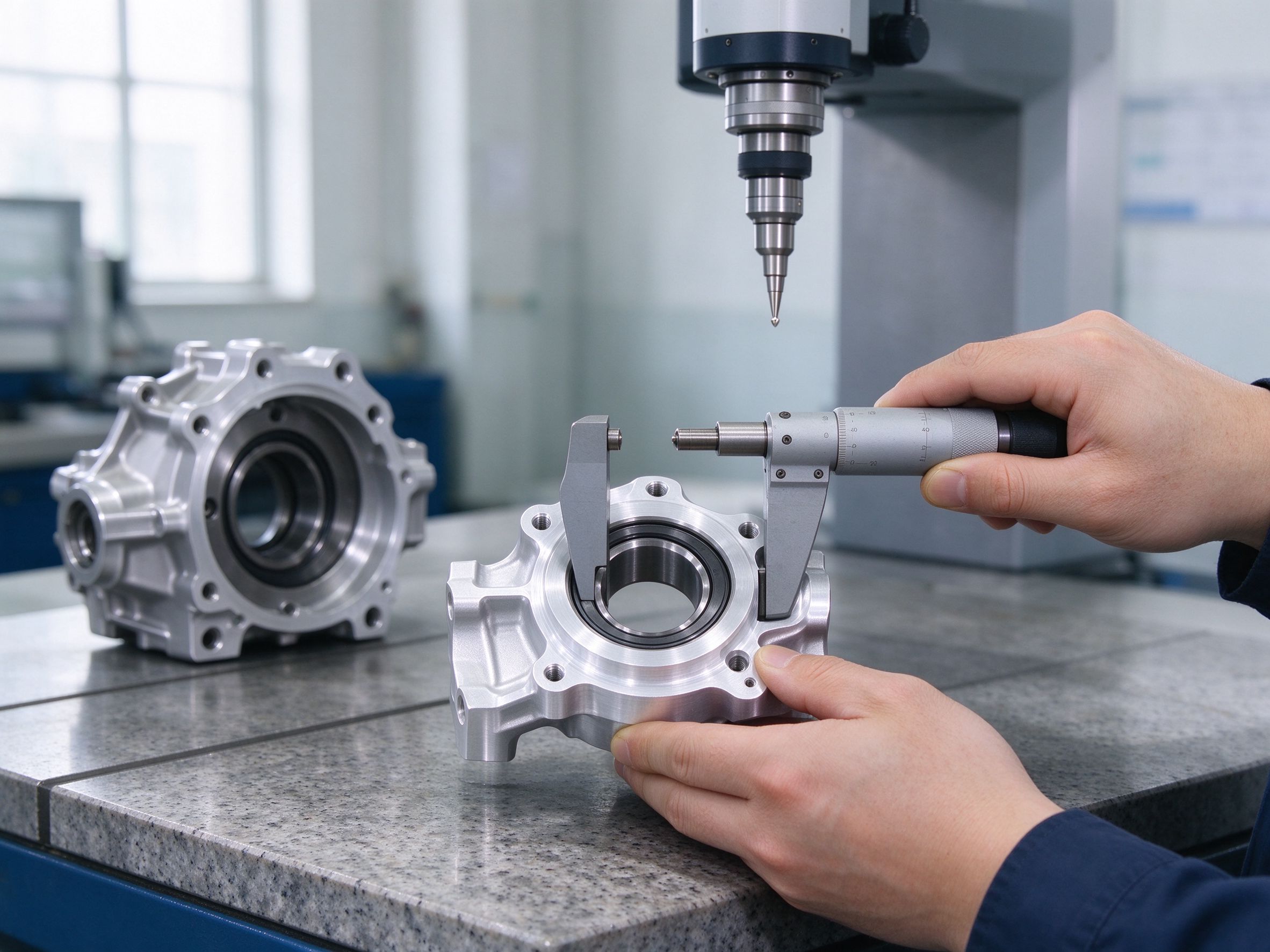
Inspection follows the drawing and the agreed inspection plan. The first-article check verifies critical features before repeat production; in-process checks watch setup and key features during the run; final inspection confirms bores, fits, threads, mating faces and surface condition before release.
Bore diameter, roundness and seat condition checked with bore gauges and micrometers.
Position, coaxiality, perpendicularity and center distance checked on a CMM where required.
Threads checked with thread gauges against the drawing specification; assembly fit verified against bearings, shafts and mating covers where the programme calls for it.
Drop, vibration, endurance, torque, thermal and corrosion tests are whole-tool-level or project-specific validations arranged against the customer test scheme and equipment.
Quality documents available on request
- Material certificate or material declaration per part number
- Dimensional inspection report with measured critical features
- First-article inspection (FAI) where requested
- Coating specification and RoHS / REACH documentation where applicable to the project
Compliance wording to keep in scope
IEC 62841 is a power tool safety standard series applied at the whole-tool level. The housing supplier follows the customer drawing, test plan and quality agreement; the part itself does not carry IEC 62841 certification. RoHS and REACH statements are provided on a project and material basis, not as a whole-tool declaration.
Quantities and Project Stages
Prototype, pilot and repeat-production parts are reviewed against the same drawing revision. The stage changes which route and cost structure fit, not which inspection standard applies.
Prototype
Single parts or small sets to validate geometry, bearing fit and the fixture concept before production. Usually CNC billet for metal housings.
Pilot batch
A small pre-production run that confirms the machining or casting process, inspection method and repeatability before scheduled batches.
Repeat production
Scheduled batches after approval, with die casting plus CNC for stable metal housings and injection molding for stable plastic shells.
Small batches carry setup, programming and fixture costs spread over fewer pieces; larger volumes amortize those costs across more units. Die and mold investment suits stable, higher-volume geometry. State the project stage and expected annual volume in the RFQ; capacity and timing are confirmed after drawing review.
What to Include in a Power Tool Housing RFQ
A complete RFQ lets the supplier assess route, tolerance, fixture and inspection method before quoting. A model alone cannot define fit and tolerance; the 2D drawing carries those.
| Package item | Why it is needed |
|---|---|
| 3D CAD model | Review geometry, ribs, bosses and internal feature access; formats such as STEP, STP, IGES or X_T. |
| 2D engineering drawing | Dimensions, datums, GD&T, tolerance tiers and surface requirements by feature. |
| Gearbox assembly drawing | Show bearing arrangement, shaft layout and how the housing sits against the gear train and motor. |
| Bearing specifications | Confirm bearing outer ring size and fit so the bore seat is sized and inspected correctly. |
| Shaft center distance | Define the gear alignment target the housing bores must hold. |
| Motor interface | Motor seat, mounting face, hole pattern and rotor clearance geometry from the mating motor end. |
| Torque and speed conditions | Describe the load and duty cycle the bosses, ribs and bearing supports must carry. |
| Material or alloy | Metal grade or plastic family, condition and any required material declaration. |
| Annual volume by stage | Set the route: billet prototype, die-cast production, or molded plastic production. |
| Surface finish | Coating, masking and appearance requirements for metal and plastic parts. |
| Validation requirements | Vibration, drop, torque, thermal or corrosion conditions and the test scheme that applies. |
| Inspection criteria | Critical-to-quality features, measurement method and required reports. |
| Delivery condition | Raw casting, CNC machined housing, finished housing or housing subassembly. |
| Packaging requirements | Protection, labeling and export packaging for bores, faces and coated surfaces. |
Frequently Asked Questions About Custom Power Tool Housings
What are custom CNC power tool housings?
Can one manufacturer produce both the metal gearcase and the plastic outer shell?
What materials are used for power tool gearcase housings?
Is a power tool housing CNC machined from solid billet or die cast?
How are bearing bores machined and controlled in gearcase housings?
How do you control gear shaft alignment and center distance?
What motor mounting geometry must be specified on the drawing?
Which CNC processes are used on power tool gearcases?
What surface finishes apply to aluminum and magnesium housings?
How are power tool gearcase parts inspected and validated?
What quantities do you accept for power tool housing projects?
What information should a power tool housing RFQ include?
Develop Your Custom Power Tool Housing with Goldcattle
Send your CAD model, engineering drawing and assembly arrangement. Our engineering team reviews the bearing layout, motor interface, material and route, then confirms the machining or casting plan, tolerance tier and inspection method before quoting.
2D drawing with revision, 3D model, bearing or gear arrangement and annual volume. One inquiry per project.
Explore manufacturing capabilities →