Custom CNC-Machined Components for Driveline Applications
Goldcattle machines the individual parts that make up driveline systems — shafts, flanges, yokes, adapters, splined components and hubs — to your drawing. This page explains what we make, the manufacturing route, the technical requirements we work to, and the engineering boundary of what we supply.
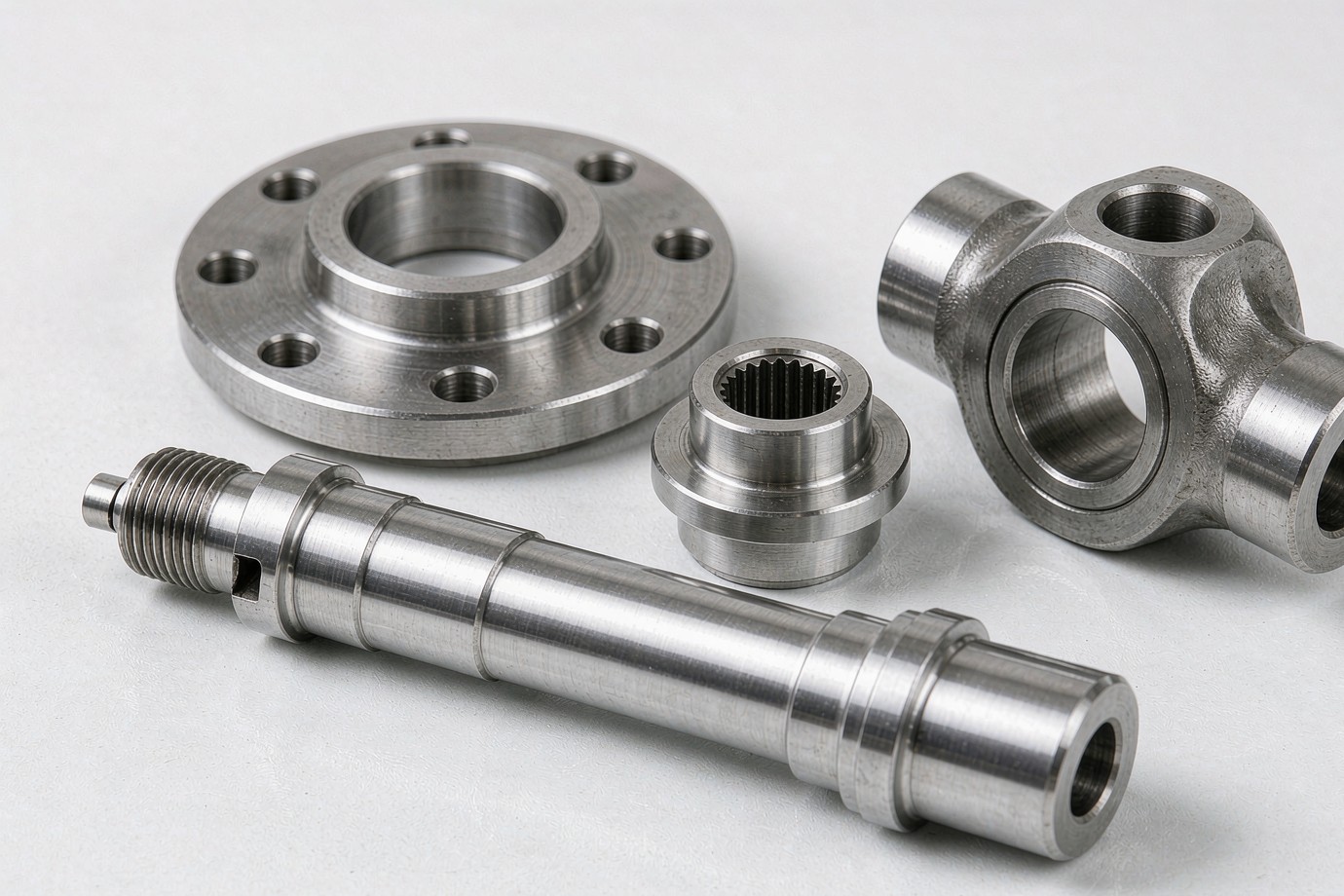
Goldcattle machines individual driveline components — shafts, flanges, yokes, adapters, splined shafts, hubs, collars and spacers — to customer drawings using CNC turning and milling. We do not design complete driveshaft assemblies, perform dynamic balancing, validate torque or load ratings, or certify fitment to a specific vehicle. The parts are supplied as discrete machined components that the buyer or a driveline assembler integrates into the finished system.
At a glance
What We Machine for Driveline Systems
A driveline moves torque from a power source to the wheels, propshaft or driven unit. Many of its parts are classic rotational components, which is exactly where CNC turning and turn-mill excel. Goldcattle's role is to produce those individual parts accurately and repeatably — to drawing, in the material specified, with the inspection the function requires.
The key distinction for a buyer is between a machined component and a finished driveshaft assembly. We supply the former. The latter combines tubing, joints, balancing and integration, which sits outside the work described here. Stating this boundary up front keeps expectations and procurement decisions clean.
Common Component Types
The table groups the driveline parts we most often machine and the features that matter when you define them. It is a typical scope list, not a claim that every item has been produced — confirm specific capability against your drawing.
| Component | Typical features | What to define |
|---|---|---|
| Shafts / stub shafts | Diameter steps, shoulders, journals, grooves | Diameter, roundness, runout, concentricity |
| Flanges | Pilot, bolt circle, face, lightening pockets | Bolt pattern, pilot dia, face position, flatness |
| Yokes | Bore, ears, pilot, cross-hole | Bore, pilot datum, ear width, cross-hole |
| Splined shafts | External/internal spline, major/minor dia | Spline standard, tooth count, engagement length |
| Adapters / collars | Bore, OD, keyway, clamp feature | Bore-to-OD relation, keyway, fit |
| Hubs / spacers | Cylindrical body, bore and face | Length, diameter, surface finish, wall |
Scope note: these are representative component categories. Actual machinability depends on geometry, material and quantity. Send the drawing for a like-for-like assessment rather than assuming a category is auto-qualified.
Engineering Boundaries — What We Do and Don't Supply
Being explicit about scope protects the buyer. The following statements are deliberately conservative and reflect how the work is actually performed.
Discrete machined components to your drawing — shafts, flanges, yokes, adapters, splined parts, hubs, collars and spacers.
Complete driveshaft assemblies, tubing and joint integration, dynamic balancing of finished rotating assemblies, or torque/load validation.
Your specified tolerances, materials, surface finish and inspection plan, with ISO 9001:2015 process control.
Fitment to a specific vehicle or application, or performance ratings of a finished driveline. Those belong to the assembly or integration stage.
If your requirement is a finished, balanced and validated driveshaft, the appropriate supplier is a driveline assembler; Goldcattle can be the source for the precision-machined components within it. This separation is the honest way to source the parts without implying capabilities that are not performed.
CNC Machining Capabilities
Driveline components span both rotational and non-rotational features, so the work is usually a mix of turning and milling. The diagram marks the interfaces a reviewer checks on a typical shaft-and-flange part.
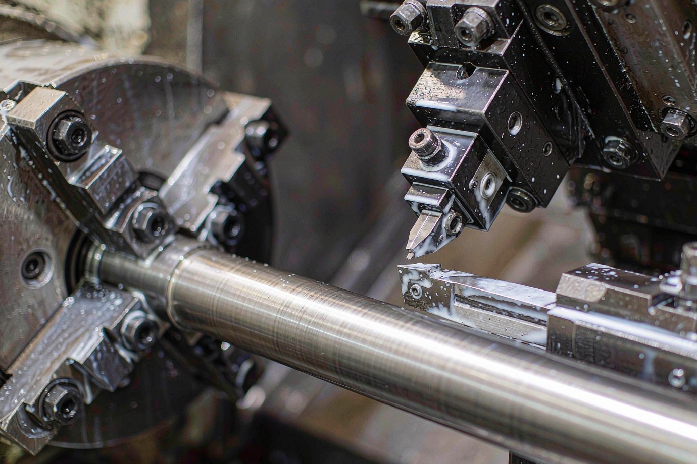
- CNC turning forms the rotational body — diameters, shoulders, grooves and internal bores.
- Live-tooling turn-mill adds flats, slots, cross-holes and bolt-circle features in fewer setups.
- CNC milling handles flange faces, ears, keyways and non-rotational details.
- Multi-axis capability supports complex interface geometry where the part needs it.
Technical Requirements: Tolerances, Materials & Surfaces
A tolerance only earns its cost when it is tied to a feature that functions. Specifying one blanket tolerance for an entire part can raise price without improving the part where it matters. Define the tight numbers at the features that locate, seal or transmit load, and relax them elsewhere.
| Requirement | What the buyer should define |
|---|---|
| Diameter & length | Nominal size, tolerance, measurement location |
| Runout / concentricity | Datum axis, method and functional need |
| Spline / thread | Standard, tooth count or pitch, class, engagement length |
| Bore & pilot | ID, depth, relation to OD and to flange face |
| Face & flatness | Position, perpendicularity to datum, finish |
| Surface finish | Ra value and its location, since finish varies along the part |
| Material | Grade, condition, certificate requirement |
Material choice is a trade-off between strength, fatigue behaviour, corrosion resistance, machinability and cost. Alloy and stainless steels, aluminum and titanium all machine well when the grade and condition are stated; the achievable dimensional results depend on the feature, material, setup and measurement method and should be confirmed per project.
Quality Control & Documentation
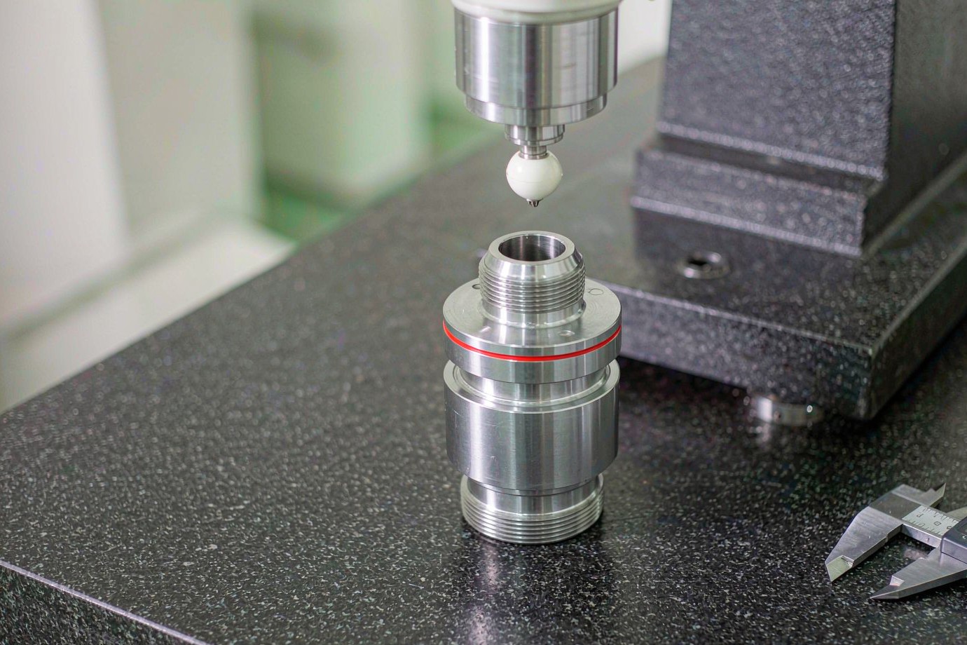
Inspection follows the drawing, not a generic "precision" claim. What gets checked is driven by the features you marked as critical.
| Inspection object | What the buyer should specify |
|---|---|
| Diameter & length | Nominal size, tolerance, measurement location |
| Runout / concentricity | Datum, method, functional need |
| Spline / thread | Standard, class, effective length, check method |
| Bore & pilot | ID, depth, relation to OD and flange face |
| Face position | Perpendicularity, flatness, surface state |
| Material | Grade, condition, certificate requirement |
| Documentation | Material cert, dimensional report, FAI per AS9102 on request |
Goldcattle operates under an ISO 9001:2015 quality system and can supply material certificates, dimensional inspection reports and First Article Inspection per AS9102 on request. State the documentation requirement when you request a quote so it is built into the production plan rather than added afterwards.
RFQ Checklist for Driveline Components
A model alone rarely carries the full requirement. Send enough that the supplier can plan the route and quote like-for-like:
- 3D CAD model and 2D engineering drawing
- Material grade and condition
- Critical diameters, lengths and face positions
- GD&T and datum requirements where applicable
- Spline or thread specification (standard, count/pitch, class, length)
- Surface roughness and finish requirements
- Bolt-circle and pilot details for flanges
- Prototype quantity and production forecast
- Material certificates or inspection reports required
- Packaging, marking and destination
Do not send only a STEP file without marking the functional diameters, datum, spline standard and key dimensions. The model shows geometry; it does not state material, final tolerance, finish or inspection. For turned and splined parts especially, the drawing carries the requirement the supplier quotes and inspects against.
When your specification is ready, you can start a quote through the online CNC quote or the project form.
Goldcattle Services
Xiamen Goldcattle Plastic & Metal Products Co., Ltd. (Founded in 1998) performs CNC machining as part of its six in-house core processes — CNC machining, injection molding, mold making, 3D printing, die casting and sheet metal fabrication — under one ISO 9001:2015 quality system. For driveline components, the relevant capability is drawing-based CNC turning and milling of discrete parts; complete-assembly, balancing and validation work is outside this scope. For verified turning capabilities and machine configuration, see the dedicated CNC turning services page, or the guide to CNC-turned parts. Grade-level material options are listed in the materials hub.
Discuss Your Driveline Component Project
Send your drawing and requirements. Our engineering team will review geometry, materials and critical features, then propose a manufacturing route and a like-for-like quote for the machined components.
Discuss Your Driveline Component Project Review full turning capabilities