Custom Industrial Machinery Components for OEM Equipment
Xiamen Goldcattle Plastic & Metal Products Co., Ltd. makes custom metal and engineering-plastic components for industrial machinery: shafts, gear blanks, housings, pump and valve parts, mounting components and wear parts. This page is organised around what a machinery buyer needs to verify before placing a repeat order — the part's function, its process route, its critical features and the records that come with it.
- OEM equipment
- Build-to-print
- Metal & engineering plastic
- Six core processes
- Repeat supply
- Production basisYour 2D drawing or 3D model
- Process scopeSix core processes, in-house
- Quality systemISO 9001:2015 certified
- EstablishedFounded in 1998
A Short Answer for Machinery Buyers
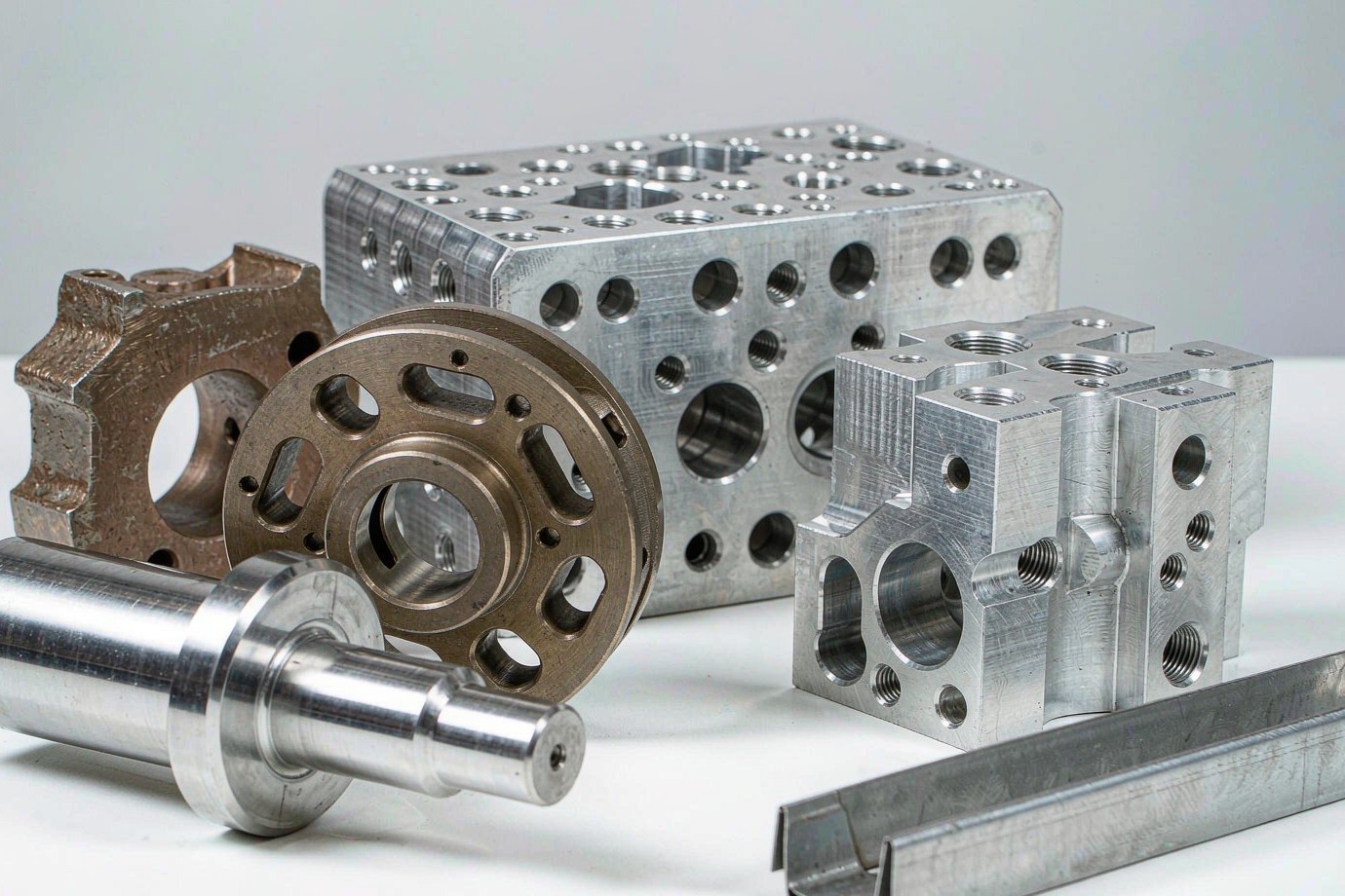
Custom industrial machinery components are parts made to an equipment maker's drawings, not bought from a catalogue. We review the drawing, the function of the part in the machine and the expected order quantity, then propose a process route, a material and an inspection plan. Metal and engineering-plastic parts can be routed through different processes inside one quality system. What you can verify before ordering — critical features, datum scheme, first article records and revision control — matters more than a general promise about precision.
What can you make?
Shafts, gear blanks, gearbox housings, bearing housings, pump and valve parts, manifolds, brackets, guards, bushings, rollers and wear plates, to your drawings.
How is it made?
CNC machining, injection molding, die casting, sheet metal fabrication, 3D printing and mold making are chosen part by part, not applied to every part.
How is fit controlled?
Bearing seats, bores, mounting faces, hole positions and sealing faces are reviewed feature by feature against the drawing's datum scheme.
What do I receive?
An approved first article, an agreed control plan, batch records and the inspection or material documents named in the quotation.
What This Page Covers, and What It Does Not
Our CNC service pages explain processes. This page explains how a machinery buyer qualifies a supplier for a part that has to fit, run and be ordered again. Keeping the two subjects separate helps both readers: the process pages answer "how is it made", this page answers "can this supplier hold my part over repeat orders".
This page is about
- Which machine functions and part families we quote
- How a process route is selected for each part
- How critical features and datum schemes are reviewed
- What records a buyer can ask for before a repeat order
- Where our gear and fluid-component scope ends
This page is not
- A catalogue of stock parts with fixed sizes or prices
- A list of machine models or axis counts
- A claim of finished-gear quality grades for every part
- A pressure rating or conformity certificate for assemblies
- A set of named customer case studies or test figures
| Supply model | OEM/ODM build-to-print. Samples can start from one piece where no dedicated tooling is needed. |
|---|---|
| Process scope | All six core processes — CNC machining, injection molding, mold making, 3D printing, die casting and sheet metal fabrication — are performed in-house under one ISO 9001:2015 quality system. |
| Equipment scale | 100+ machines across six processes in total, covering all six core processes rather than one workshop. |
| Dimensional basis | The drawing, its datum scheme and the customer requirement. No blanket tolerance figure is published here. |
| Documents | Named per project in the quotation. A dimensional record is not a finished-equipment assessment. |
| Established | Founded in 1998. Customers in 100+ countries. |
Five Machine Functions, Not a Part Catalogue
Machinery buyers rarely search for a process. They arrive with a function the part has to perform inside a machine. The five groups below are the way we organise an enquiry, because each one brings a different set of critical features and a different supplier question.
- 01 Power transmissionGears, gear blanks, shafts, hubs, couplings, gearbox housings, bearing seats.Fit, runout, concentricity, wear.
- 02 Motion controlActuator parts, mounting brackets, fixture plates, guide components, motor housings.Position, stiffness, repeat assembly.
- 03 Fluid handlingPump housings, valve bodies, manifolds, impellers, fittings, fluid connectors.Sealing faces, bores, internal channels.
- 04 Machine structuresMachine bases, structural brackets, equipment housings, mounting plates, guards, enclosures.Flatness, hole position, surface protection.
- 05 Wear and handlingRollers, bushings, wear plates, guide rails, sprockets, spacers, replacement parts.Friction, load, service life.
- Name the function of the part in the machine.
- Mark the critical features on the drawing.
- Agree the process route and the control plan.
- Approve the first article, then repeat to that record.
| Function group | Features that usually decide the quote | Processes commonly reviewed | Buyer question to answer first |
|---|---|---|---|
| Power transmission | Bearing-seat diameter, shaft runout, bore concentricity, keyways and splines, thread accuracy | CNC turning and milling, injection molding for plastic gears and bushings | Does the part include a finished tooth form, or a blank and its housing? |
| Motion control | Mounting hole position, flatness of the interface, parallelism of guide faces, stiffness of thin sections | CNC milling, sheet metal fabrication, 3D printing for prototype fixtures | Is this a one-off fixture or a repeat-mounted production part? |
| Fluid handling | Sealing face finish, internal channel access, bore size, port threads, media compatibility | CNC milling and turning, die casting for suitable higher-volume housings | Is a pressure or leak test in scope, and who owns the result? |
| Machine structures | Flatness over a long surface, hole pattern, weld or bend distortion, coating coverage | CNC machining, sheet metal fabrication, die casting for selected housings | Is the part measured free-standing or in its assembled position? |
| Wear and handling | Dimensional stability, friction behaviour, hardness or surface treatment, load and lubrication | CNC machining, injection molding, 3D printing for prototypes | What are the load, speed, medium and temperature in service? |
Part Families We Are Asked to Quote
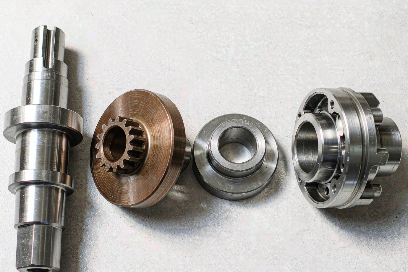
This is a map of the requests we receive, not a stock list. Each row names the critical features that should be on the drawing before the route is chosen. Where we already have a dedicated page for a part family, we link to it rather than repeating the same text here.
| Part family | Typical application | Critical features | Usual route |
|---|---|---|---|
| Precision shafts and axles | Drive assemblies, rollers, rotor supports | Bearing-seat diameter, runout, shoulders, keyways, thread ends | CNC turning, then milling or grinding where the drawing calls for it |
| Gear blanks, hubs and gearbox housings | Power transmission, reducers | Bore concentricity, mounting faces, bearing seats, bolt patterns | CNC turning and milling; die casting after a tooling review for volume |
| Mechanical housings and enclosures | Equipment bodies, motor frames, covers | Bores, flatness, threads, sealing lands, wall thickness | CNC machining for low volume, die casting plus finishing for suitable volume |
| Pump and valve components | Fluid handling, dosing, pneumatics | Sealing faces, internal channels, port threads, bore finish | CNC milling and turning; see our custom CNC pump components page |
| Manifolds and fittings | Hydraulic and pneumatic distribution | Channel intersections, port alignment, thread accuracy, sealing faces | CNC milling from solid; the fluid page covers the wider fitting scope |
| Brackets and mounting components | Equipment assembly, actuator mounting | Hole position, flatness, bend radius, stiffness of thin sections | CNC machining or sheet metal fabrication, chosen from geometry and volume |
| Bushings, bearing blocks and spacers | Guide systems, rotating supports | Bore size, wall thickness, press fit, surface finish | CNC turning; injection molding for engineering-plastic bushings |
| Jigs, fixtures and test parts | Assembly lines, inspection setups | Locating faces, repeat assembly, weight, access for clamps | CNC machining, 3D printing or sheet metal fabrication |
| Engineering-plastic wear parts | Guides, low-friction slides, conveyor parts | Dimensional stability, friction behaviour, wear, moisture uptake | CNC machining for samples, injection molding for repeat batches |
| Custom replacement parts | Maintenance and repair of installed equipment | Fit with mating parts, material identification, sample condition | Reviewed case by case after a drawing or sample review |
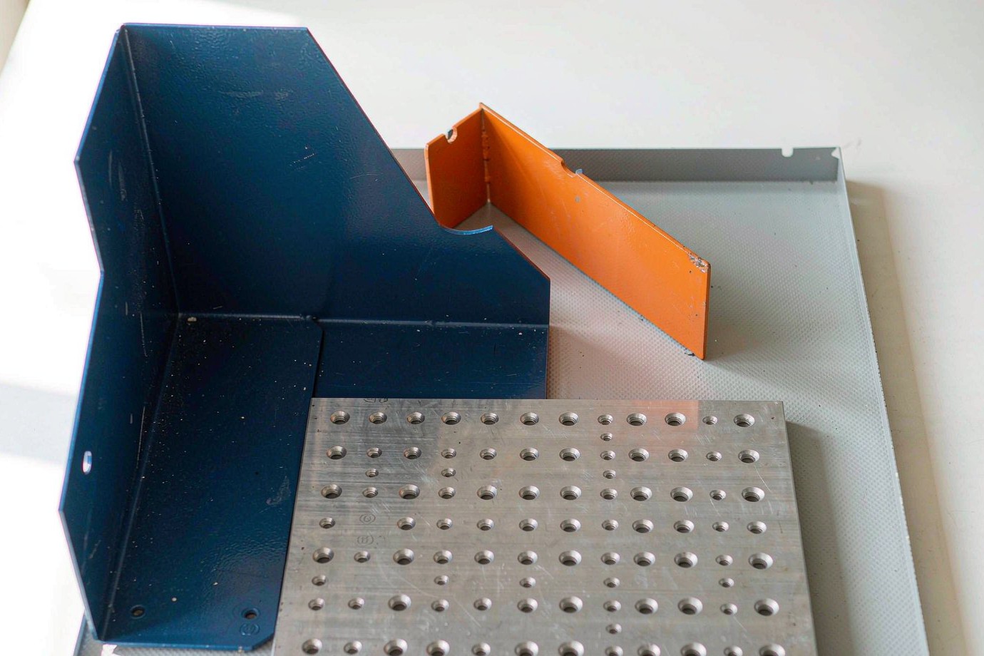
For oversized bases, frames and plates, see large precision CNC parts. For the full process overview across all part types, see manufacturing services.
Gear Components: Where Our Scope Ends
Gear-related work is a common source of misunderstanding between a buyer and a machine shop. We quote gear blanks, gearbox housings, shafts, hubs, couplings and bearing seats as build-to-print parts. Those are components defined by bores, faces, seats and hole patterns on a drawing.
A finished gear with a named tooth form and a gear quality grade is a different manufacturing problem. It calls for a defined gear cutting or grinding route and tooth-flank inspection. We do not present that as a standard capability for every enquiry. If your drawing requires it, we review the route, the inspection method and the responsible party per project before a quote is confirmed.
We do not claim a gear quality grade, a tooth-flank inspection result or a gear cutting capability that has not been agreed for the specific part. A blank, a housing and a shaft are not the same purchase as a finished, graded gear. Stating the difference at the quotation stage avoids a part that fits the housing but fails the transmission.
| Quoted as standard build-to-print work | Scoped per project before quoting |
|---|---|
| Gear blanks, hubs, spacers and coupling halves | Finished tooth forms on a spur, helical or bevel gear |
| Gearbox housings, bearing seats and mounting faces | A named gear quality grade and its inspection method |
| Shafts, keyways, shoulders and threaded ends | Gear grinding, honing or shaving after heat treatment |
| Plastic gears where tooth geometry is supplied and mouldable | Tooth geometry design, backlash calculation and gearbox performance |
Pump, Valve and Fluid Parts: A Responsibility Boundary
We machine pump housings, valve bodies, manifolds, impellers, fittings and fluid connectors to drawings. The features we control are the sealing faces, internal channels, bores, port threads and mounting interfaces that appear on the drawing. Those are dimensional and surface characteristics of a component.
A machined part is a component. It does not carry a pressure rating because it was cut accurately, and dimensional, thread or surface inspection is not the same as a pressure or leak test on an assembly.
Standards belong to the assembly and its market. Requirements such as ASME B16.34, ISO 5208, API Spec 6D and EU PED 2014/68/EU are assessed by the party placing the pressure equipment on the market. We do not state that a machined component meets them by default.
Testing is defined at quotation. If a project needs a pressure or leak test, the method, acceptance criteria, responsible party and the documents to be issued are all agreed before production, not added after shipment.
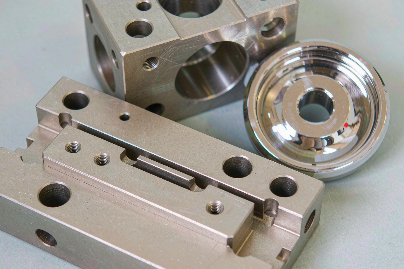
| What our inspection describes | Bore size, sealing face finish, thread accuracy, hole position and visual condition of the machined part. |
|---|---|
| What it does not describe | Pressure rating, leakage behaviour, burst strength, media compatibility over time, or conformity of the finished valve or pump. |
| Who defines the test | The buyer and the responsible party for the target market, with the method named in the project specification. |
| Who supplies the documents | Agreed in writing at quotation. A dimensional record is never presented as a pressure test certificate. |
Six Processes, Chosen Part by Part
A single equipment project rarely needs one process for every part. A shaft, a plastic guide, a sheet-metal guard and an aluminum housing each have a different economic route. The table below is the selection logic we apply at quotation; it is not a promise that every part suits every process.
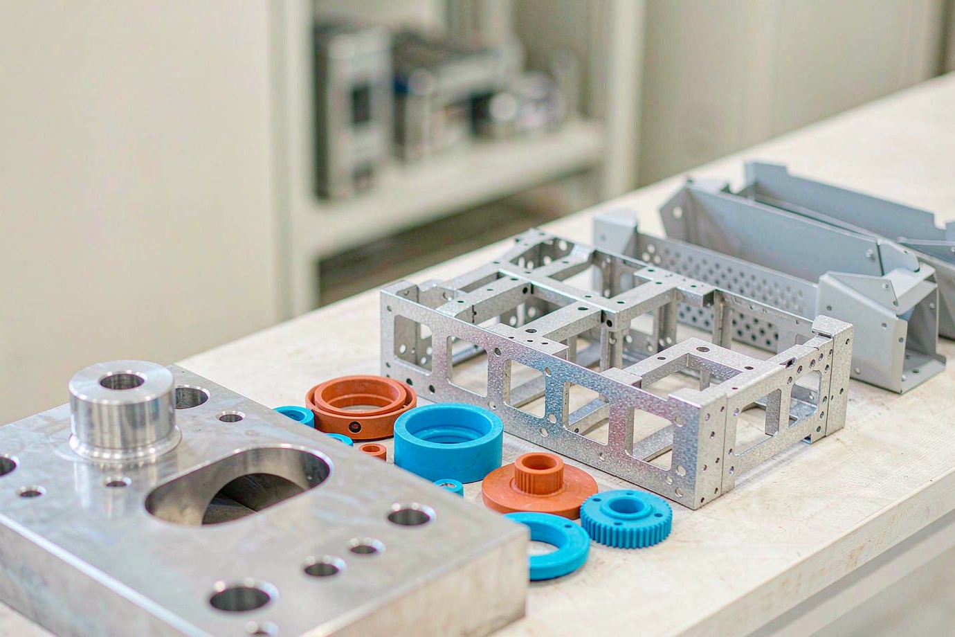
| Process | Parts commonly routed here | Why a buyer chooses it | What to settle first |
|---|---|---|---|
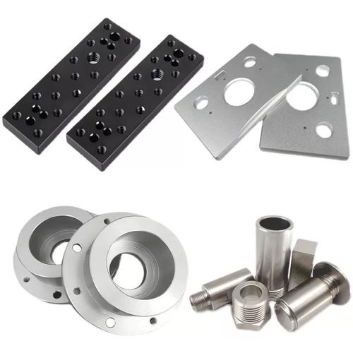
| CNC machining | Precision shafts, housings, manifolds, mounting blocks, bearing seats | Complex geometry and feature-by-feature dimensional control from a drawing | Datum scheme, critical features, inspection method |
| Injection molding | Plastic gears, bushings, guides, wear pads, covers | Repeatability for plastic parts once a tool is justified | Tooling investment, grade, shrinkage, expected volume |
| Die casting | Aluminum housings, motor frames, gearbox casings | A metal route for suitable higher-volume shapes, followed by CNC finishing | Geometry, draft, tooling cost, porosity and finishing scope |
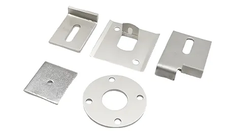
| Sheet metal fabrication | Machine guards, brackets, panels, enclosures | Formed structures and protective covers without machining from solid | Bend radius, flatness, hole pattern, coating |
| 3D printing | Functional prototypes, complex fixtures, test components | Fast design verification before a tool or a hard route is committed | Material limits, surface finish, whether the part is end-use |
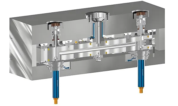
| Mold making | Tooling for plastic components and production molds | Keeps the plastic part and its tool inside one project scope | Tool ownership, revision control, maintenance plan |
Detailed process pages: CNC machining services, injection molding services, die casting services and sheet metal fabrication services.
Two Process-Route Examples
These are illustrations of how a route is selected, not specifications for a part we stock. The final route depends on geometry, material, quantity, tooling cost and the critical features on the drawing.
Industrial equipment housing
Small batch: CNC machining from solid. Higher volume: die casting plus CNC finishing, after a tooling review. Features: bores, flatness, mounting holes, sealing lands. Verification: dimensional inspection and a first article to the agreed plan. A housing is not automatically a die casting candidate.
Engineering-plastic wear component
Sample: CNC machining from the chosen stock. Repeat batch: injection molding once the tool is justified. Features: dimensional stability, friction and wear behaviour. Verification: dimensional inspection and material identification. Grade follows load, lubrication, medium and temperature.
| Decision input | Example A: housing | Example B: wear part |
|---|---|---|
| First order size | A few pieces for fit testing | One or a few samples for a wear trial |
| What justifies a tool | Forecast volume, shape suitability, finishing cost | Repeat volume, grade availability, tolerance after moulding |
| What stays constant across routes | The drawing revision and the critical feature list | The material specification and the wear acceptance point |
| What must be re-approved | A new sample after any route or material change | A new sample after any grade or tool change |
Materials by Operating Conditions
Material selection for a machine part follows the conditions it works in. The table gives starting directions, not a ranking and not a claim that a grade suits every load, medium or temperature. The exact grade, condition and any certificate requirement are confirmed against the drawing before production.
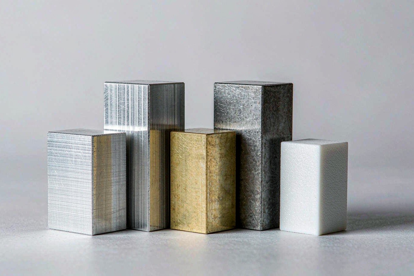
| Material family | Parts often reviewed in this family | Conditions that decide the grade |
|---|---|---|
| Aluminum alloys | Lightweight housings, mounting plates, brackets, covers | Weight, stiffness, heat exposure, surface treatment and corrosion environment |
| Stainless steels | Pump and valve parts, shafts, connectors, washdown equipment parts | Corrosion exposure, cleaning agents, temperature and required surface finish |
| Carbon and alloy steels | Drive shafts, load-bearing pins, couplings, structural connectors | Load, cyclic stress, hardness or heat treatment, wear and lubrication |
| Brass and bronze | Bushings, fittings, connectors, friction and sliding parts | Bearing behaviour, galling risk, conductivity and media compatibility |
| Engineering plastics | Plastic gears, bushings, guides, wear plates, rollers | Friction, load, moisture uptake, chemical exposure and service temperature |
Dimensional Control and Datum Schemes
For a machine part, the question is not one general tolerance figure. It is whether the features that control assembly stay stable across a batch. Bearing seats, bores, mounting faces, hole positions, threads and sealing faces each behave differently in machining, in finishing and in inspection.
| Feature | Why it matters in a machine | How it is controlled |
|---|---|---|
| Bearing-seat diameter and shaft runout | Controls fit, rotation and vibration at speed | Turning route, datum choice between centres, and a runout check to the agreed plan |
| Bore diameter and concentricity | Controls alignment of shafts and housings in an assembly | One-setup machining where possible, or a defined re-clamping datum |
| Flatness and parallelism | Controls how a base, plate or mounting face sits against its mating part | Workholding, stress relief where needed, and measurement in the agreed condition |
| Hole position and mounting interfaces | Controls whether the part assembles without forcing | Pattern checked against the datum scheme, not against a single hole |
| Thread accuracy and sealing faces | Controls joint integrity and leak path | Thread gauging and surface finish review to the drawing requirement |
Tolerances are reviewed feature by feature against the drawing and the customer requirement. The applicable datum scheme follows the geometric tolerancing standard named on the drawing — commonly ASME Y14.5-2018 R2024 or ISO 22081:2021 — and those two systems are not interchangeable. A tight value applies only to qualified features after a drawing and manufacturing review; it is never a blanket figure for every dimension on every part. The inspection method is agreed before production release.
Wear, Vibration and the Working Environment
A part that measures correctly at incoming inspection can still fail early in service. Machinery components see continuous friction, cyclic loading, vibration, impact, cleaning chemicals, moisture and elevated temperature. These conditions change material, surface treatment and process choices, so they belong in the first enquiry rather than in a later complaint.
Sliding and rotating contact
Guides, bushings and wear plates are reviewed for friction behaviour, lubrication, surface finish and how the grade behaves when it absorbs moisture.
Cyclic stress and impact
Shafts, pins and structural brackets are reviewed for load path, section changes, stress concentrations and the chosen heat treatment or condition.
Chemicals, washdown, heat
Pump and valve parts, seals and enclosures are reviewed for the medium, cleaning agents and service temperature before a grade is fixed.
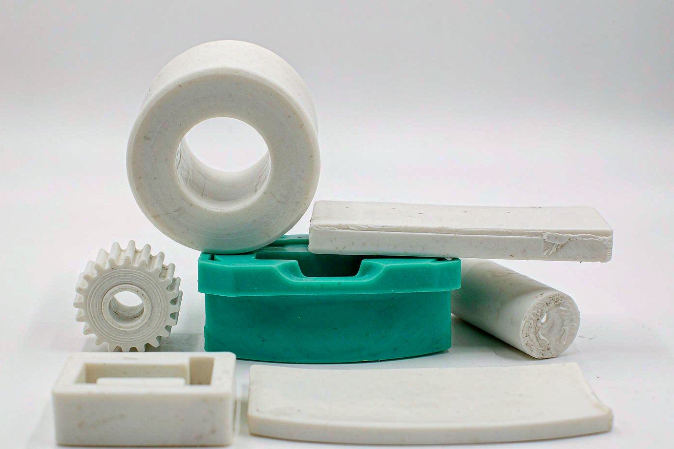
Tell us what the part is exposed to. If a condition is not yet known, we list it as an open point at quotation rather than picking a material that happens to be available.
Inspection Records and Traceability
Industrial buyers often audit a supplier before a repeat order. The records below are the ones that can be agreed in a control plan. Which ones apply is defined per project; we do not describe a document as available unless it is in the quotation.
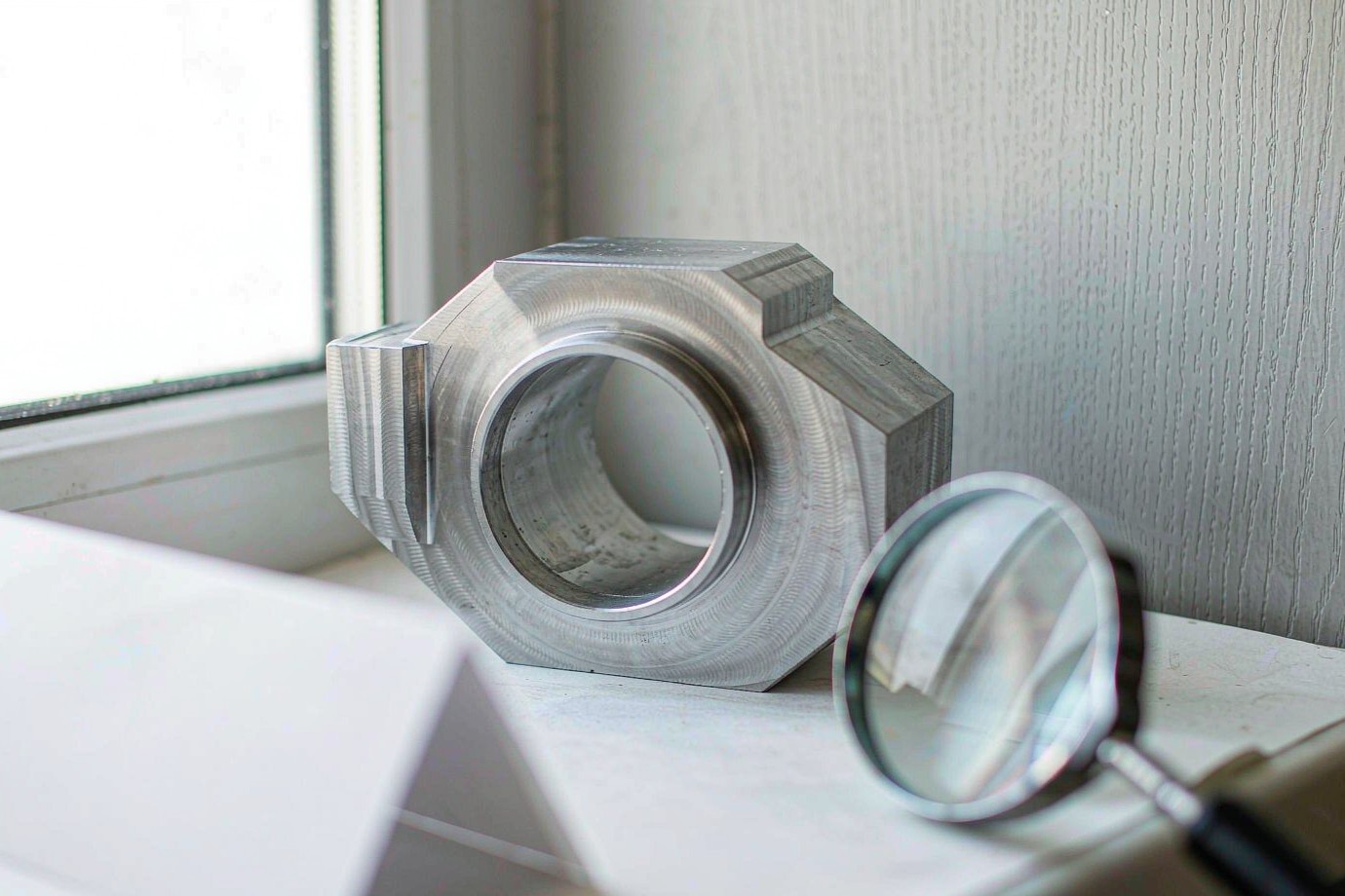
- Drawing revision controlThe revision used for the quote, the first article and each repeat order is recorded and confirmed before production.
- First article inspectionThe agreed critical features are checked on the first article against the drawing and the control plan.
- In-process checksKey features are checked during the run, with attention to tool wear, setup changes and material batch changes.
- Material informationGrade and batch identification are supplied where the project calls for them.
- Final inspectionDimensional and visual condition are reviewed before packing, with the agreed record issued at shipment.
- Repeat order referenceThe approved article, the control plan and the record set are the reference for the next batch.
From Drawing Review to Repeat Orders
Most machinery projects are not a single sample. They move from a design check to an approved first article and then to repeat orders. Each gate below has an output a buyer can hold the supplier to.
- GATE 01
Drawing and requirement review
2D or 3D CAD, material, quantity, function in the machine and required documents are collected.
- GATE 02
DFM and process selection
Critical features, datum scheme, material and manufacturing route are proposed in writing.
- GATE 03
Sample and first article
A sample is made and the agreed features are checked before production release.
- GATE 04
Production and in-process checks
The batch is built to the approved article with the agreed control plan applied.
- GATE 05
Final inspection and delivery
Final records, packing and shipment are completed to the agreed scope.
- GATE 06
Repeat order
The approved article, drawing revision and record set are reused as the reference.
Our general planning bands are three to seven working days for prototypes, seven to twenty working days for low-volume work and fifteen to twenty-five working days for production runs. These are initial engineering references for the site as a whole, confirmed per project at quotation. A part that needs a new tool, a special finish or a named inspection document is not scheduled the same way as a simple machined sample.
Who Reviews Your Enquiry
Three people often read the same page and look for different things. Covering all three in one place shortens the internal approval chain on the buyer's side.
Will it fit and run?
Looks for manufacturability, the datum scheme, fit tolerances, material behaviour and whether the drawing's critical features are understood before cutting starts.
Can we rely on supply?
Looks for a clear quote, quantity bands, tooling cost shown separately, quality system, documents, packing and the reference used for repeat orders.
Will the replacement match?
Looks for whether a worn sample or an old drawing is enough, how fit with mating parts is checked, and whether the same part can be ordered again later.
| Reviewer | Question they need answered | Where this page answers it |
|---|---|---|
| Design engineer | Are the critical features and the datum scheme understood before cutting starts? | Five machine functions, dimensional control, working environment |
| Sourcing manager | Is tooling shown separately, and what records come with each repeat order? | Cost, quantity and lead time; inspection records and traceability |
| Maintenance buyer | Can a worn sample or an old drawing be turned into a repeatable replacement part? | Part families, project records, what to send for a quote |
Cost, Quantity and Lead Time
A useful quote shows the inputs, so a buyer can change one on purpose. We quote tooling separately from unit price and list the finishing and document scope in writing. The table names the inputs that actually move a machinery-part quote.
| Geometry and setup | Number of setups, datum complexity, thin walls, deep bores and access for tools or supports. |
|---|---|
| Critical features | How many dimensions need a dedicated check, and whether a secondary operation or a special gauge is needed. |
| Material and condition | Grade availability, stock form, any heat treatment or surface treatment, and waste on the starting stock. |
| Tooling | Whether a mold or die is justified by the forecast volume. Quoted as its own line, not hidden in the unit price. |
| Quantity bands | Prototype, low-volume and production quantities are quoted separately so the setup cost is visible. |
| Finishing and documents | Coating, marking, packing, material information and the inspection records named in the quotation. |
| DFM options | Material alternatives, tolerance review on non-critical features and geometry changes that reduce setups — proposed only where the function allows them. |
Project Records Instead of Case Claims
We do not publish named machinery customers, invented order volumes or test results on this page. Industrial buyers verify technical claims, and an unverifiable case study is worse than no case study. What we can do is show the structure of a real project record and discuss evidence during a specific enquiry where a confidentiality arrangement allows it.
| Record field | What it contains | Why a buyer asks for it |
|---|---|---|
| Part and function | Part name, the assembly it belongs to and its job in the machine | Confirms the supplier understood the application, not just the shape |
| Drawing revision | The revision used for quoting, first article and each repeat order | Prevents an old revision being built months later |
| Material and batch | Grade, condition and batch identification where agreed | Supports traceability if a question appears in service |
| Critical feature list | The dimensions and geometric controls agreed at quotation | Makes the control plan auditable instead of general |
| Inspection method | How each critical feature was checked and with what record | Shows whether the measurement matches the requirement |
| Change record | Any material, route or drawing change and the new sample approval | Explains differences between two batches |
Samples, project records, material information and factory evidence can be reviewed during a specific enquiry. Where a photograph or a report contains customer information, it is shared only under an agreed confidentiality arrangement.
What to Send for a Quote
A complete first message usually removes one full round of questions. Send what you have and mark the open points; we will come back with the specific gaps rather than a general request for more information. If you are not sure which process or material fits, say so — that is a normal starting point, not a reason to wait.
- A 2D drawing or 3D model with the revision, and the file format noted.
- The part's function in the machine and the assembly it mates with.
- Critical dimensions, geometric tolerances and the datum scheme, where defined.
- Material and grade if fixed; otherwise the load, medium, temperature and wear conditions.
- Sample quantity, expected production quantity and any forecast for repeat orders.
- Surface treatment, marking, assembly or special packaging needs.
- The inspection, material or other documents you expect with the shipment.
- For replacement parts, a sample or the old drawing plus any known fit problem.
- Any drawing or specification that must stay under a confidentiality arrangement.
Questions Machinery Buyers Ask
What are custom industrial machinery components?
Which industries and equipment do you supply?
Can you make finished gears to a specified gear quality grade?
Do you certify pump and valve parts for pressure service?
What tolerances can you hold on machinery parts?
Which materials do you work with for machinery components?
How do you decide which manufacturing process to use?
Can you make both metal and plastic parts for one machine?
What inspection documents can you provide?
Can you make replacement parts from a sample or an old drawing?
How do you keep repeat orders consistent?
What should I send to get a quote?
Ready to send your machinery drawings?
Send the drawing, the part's function in the machine, the material if fixed and the quantity you expect. We will return a drawing review, a proposed process route, the critical features we would control and a quote that lists tooling, finishing and documents as visible inputs.
Request a Quote for Industrial Machinery Components Explore all manufacturing servicesXiamen Goldcattle Plastic & Metal Products Co., Ltd. — Founded in 1998 · ISO 9001:2015 certified · OEM/ODM build-to-print.