Custom CNC Machined Instrument Mounting Brackets
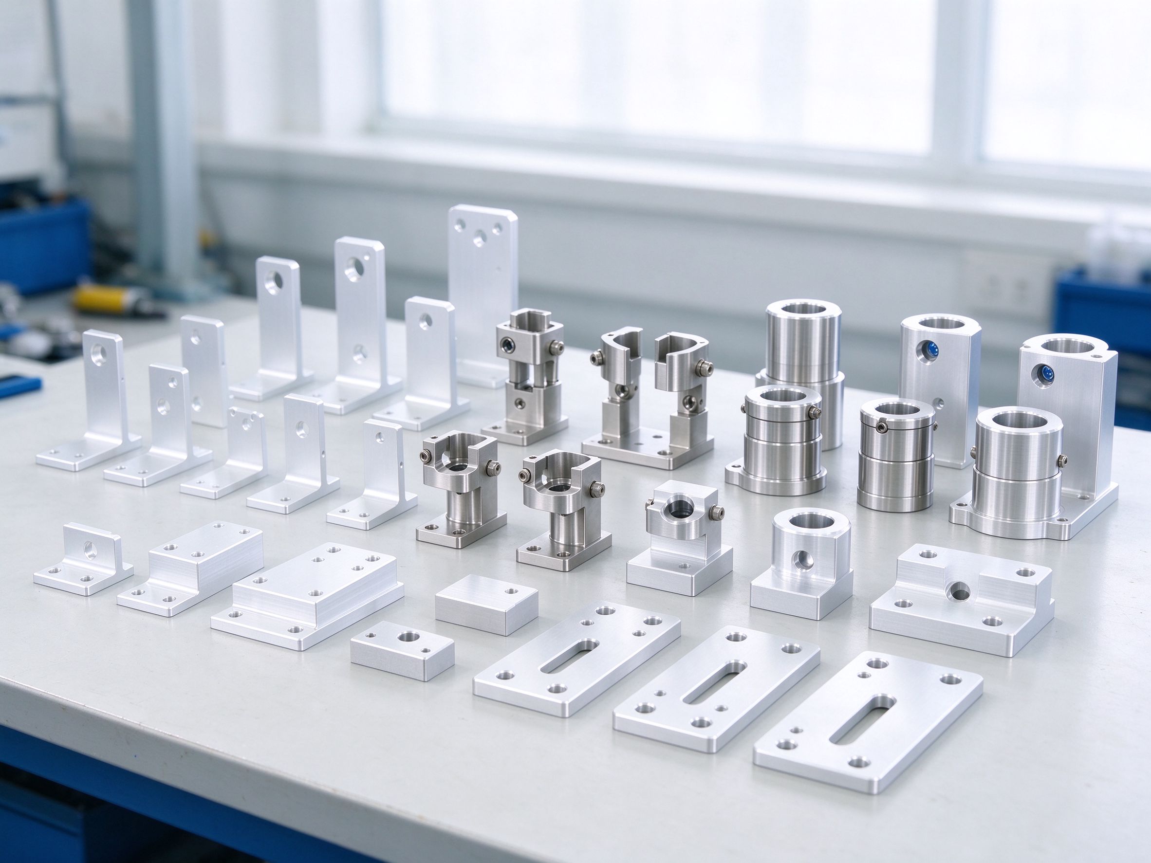
Goldcattle manufactures precision CNC instrument brackets and mounting components for industrial sensors, optical equipment, measurement instruments and automation systems. From sensor holders and probe mounts to optical alignment brackets and custom instrument plates, parts are machined to your drawings with defined mounting interfaces, functional datums, hole patterns and inspected critical features.
At a Glance
Goldcattle machines custom sensor, optical, probe and instrument mounting brackets from buyer drawings. We focus on parts where the mounting hole pattern, reference datum, mating bore and instrument axis must stay controlled and repeatable. Materials, critical features, machining route and inspection method are reviewed against the drawing and agreed inspection plan, with CMM records and material documents available on qualified lots.
What We Machine
Instrument brackets are grouped by the equipment they hold, not by alloy or general shape. Each family carries its own interface features and inspection points, so the drawing review separates what fits the instrument from what fixes it to the machine.
Photoelectric, laser, proximity and vision holders
Clamps and brackets for sensor housing diameters, with circular bores, split clamps, adjustment slots, tapped threads, dowel holes and the sensor axis defined against the machine face.
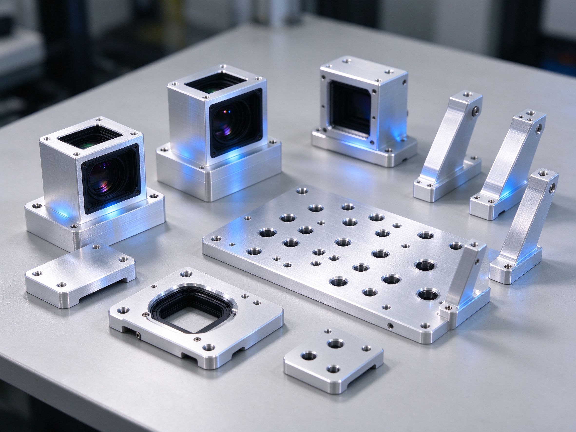
Camera, lens and laser alignment blocks
Camera brackets, lens support blocks, optical module seats and vision mounting plates where face flatness, bore position and angle to the optical path are reviewed.
Probe, metrology sensor and inspection supports
Cylindrical probe clamps, measuring-head blocks and calibration fixture supports with reference datums, probe axis alignment, bore location and repeatable seating faces.
Transmitter, gauge and interface adapters
Special transmitter adapters, instrument support blocks, gauge brackets and interface plates for non-standard housings, hole patterns or multi-instrument mounting arrangements.
Instrument plates and multi-sensor blocks
Support plates, multi-sensor mounting blocks, equipment adapter plates and precision frames with controlled hole patterns, datum flatness, thickness and thread quality.
Bores, slots, dowels, threads and datum faces
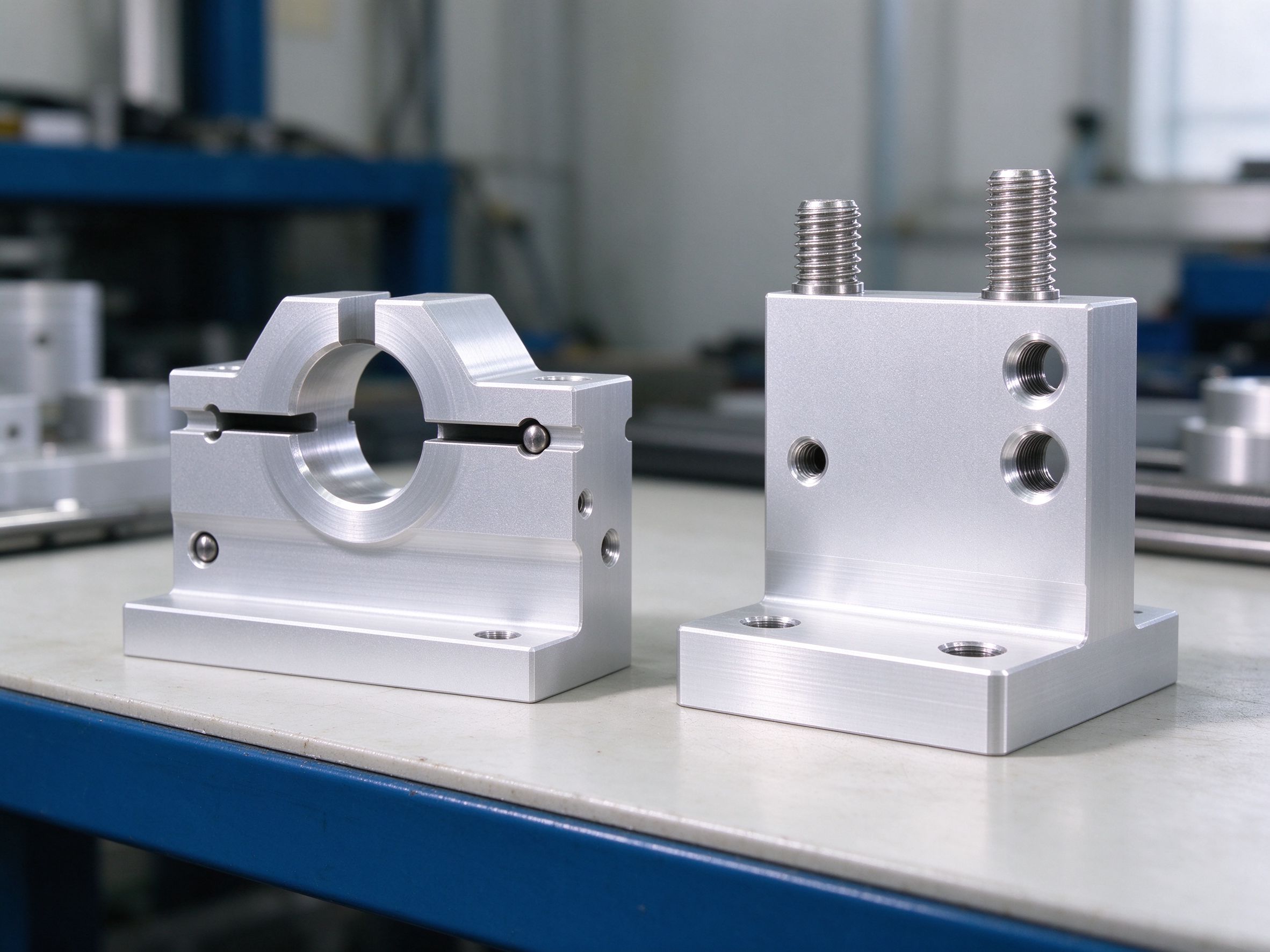
Reamed and tapped holes, clamping bores, adjustment slots, pin holes, angled faces and mounting flanges are machined and inspected against the agreed feature list.
Instrument Interfaces and Mounting Geometry
A bracket must match both ends: the instrument body and the machine or frame. The buyer drawing or assembly note should define which features belong to the sensor interface, which belong to the machine reference, and where adjustment remains available.
| Interface element | What it defines | Review point |
|---|---|---|
| Instrument make and model | Reference for body shape and mounting standard | Confirmed from drawing or catalog data; no assumed universal fit |
| Body dimensions and housing diameter | Size of the clamp, seat or bore | Clearance, fit and clamp contact face |
| Mounting hole pattern | Position and spacing of fasteners | Hole true position and edge distance |
| Thread size and pitch | Tapped holes or mounting studs | Thread gauge check and engagement length |
| Dowel pin locations | Repeat location on reinstall | Pin hole size, position and datum relation |
| Mounting surface dimensions | Mating face to machine or bracket | Flatness and perpendicularity where required |
| Sensor, probe or optical axis | Direction the instrument points | Angular relation to reference datums |
| Cable and connector clearance | Space for lead, plug and bend radius | Tool access and assembly direction |
Datum Control and Critical Geometry
The datum reference frame links the instrument axis to the machine reference. On a bracket, the judged features are usually a base mounting face, one or two side faces, a locating bore or pin hole, and the instrument interface. The machining sequence and inspection plan use the same datums as the assembly.
| Critical feature | Technical requirement | Inspection method |
|---|---|---|
| Mounting hole position | True position relative to datums | CMM |
| Base flatness | Seating face lies within flatness band | CMM or precision height inspection |
| Perpendicularity | Standing face to base reference | CMM |
| Parallelism | Related mounting faces stay parallel | CMM |
| Bore alignment | Sensor or probe axis to reference | CMM or appropriate geometric measurement |
| Dowel pin hole | Pin size and locating position | Pin gauge and CMM |
| Adjustment slot | Slot width, location and travel | Caliper or CMM |
| Mating surface roughness | Finish on contact or seal faces | Surface roughness tester |
Tolerance and GD&T
One headline tolerance does not fit every bracket. General outline and non-mating features run to a wider band; controlled finishing features sit in a middle band; qualified critical features are evaluated against the drawing, material and inspection method before a tight value is quoted.
Around ±0.02 mm
Typical reference for general machined features under ISO 2768-f fine, such as non-mating holes, outline and slots.
Around ±0.01 mm
For selected mating faces, holes and turned features after setup review and agreed inspection.
±0.005 mm reviewed
Applies to reviewed CTQ bores, locating surfaces, hole position or flatness after drawing, material and inspection review, not to the whole part.
Common geometric controls include position, flatness, parallelism, perpendicularity, runout and profile. A tolerance that tightens with feature size also raises machining and inspection cost, so only functional interfaces carry the narrowest band. Review our tight-tolerance CNC machining services for the inspection approach behind controlled features.
Rigidity, Vibration and Thermal Stability
The bracket carries the sensor, instrument housing, probe assembly, optical module, camera and lens, plus cable and connector loads. A part that passes static dimension checks may still flex under a long cantilever, thin section or equipment vibration, so geometry is reviewed against the stated load and mounting direction.
Cantilever length and arm reach
Shorten reach, widen support or add a rib or second leg where load requires.
Base thickness and contact area
Use enough base section and seating area to spread fastener clamp load and resist rocking.
Fastener spacing and pockets
Space bolts for clamp load, balance weight-reduction pockets against local stiffness and keep ribs where deflection would matter.
Thermal stability enters when temperature changes move the relative position between instrument and machine. Material thermal expansion, operating temperature range, temperature gradients and contact material are considered together with weight, load and corrosion need. A single alloy is not assumed best for every metrology or optical setup.
Adjustability and Repeated Installation
OEM equipment often needs a limited adjustment range during setup, then a repeatable position after maintenance. The drawing decides which features handle adjustment and which handle final location; the two roles should not be mixed on the same face.
| Feature | Buyer value | Design note |
|---|---|---|
| Slotted mounting holes | Limited position adjustment after install | Slot width and travel defined; contact area after tightening reviewed |
| Shim faces | Fine height or parallel relation | Seat face flatness and shim thickness allowance |
| Dowel pin holes | Consistent location on reinstall | Pin size, position and assembly order |
| Reamed bores | Specified fit and location | Bore tolerance and mating diameter |
| Threaded inserts | Repeat assembly or thread maintenance | Reviewed for softer material and repeated use |
| Cable routing clearance | Connector and lead access after install | Bend radius and assembly direction checked against model |
CNC Machining vs Sheet Metal Fabrication
Not every instrument bracket needs CNC machining. Standard pipe or panel transmitter mounts, simple L-tabs and high-volume simple supports may be covered by formed sheet metal. CNC suits alignment-critical seats, multi-face interfaces and precision bores that sheet bending cannot hold directly.
| Factor | CNC machined bracket | Sheet metal bracket |
|---|---|---|
| Raw material | Plate, bar or blank | Thin metal sheet |
| Typical structure | 3D seats, thick-wall holders, locating blocks | L, U and Z shapes, bends, clamps and panels |
| Hole position | Suited to controlled multi-face hole patterns | Affected by bend, die and material springback |
| Datum surfaces | Multiple related faces can be finished in sequence | Formed mainly from sheet surface and bend structure |
| Locating bores | Reamed bores and dowel holes machined directly | Plain punched holes; special bores may need second operation |
| Structural rigidity | Section, ribs and geometry tuned in material removal | Bends and stiffening features add rigidity |
| Tooling | Usually no dedicated stamping die | Simple bends need little tooling; high-volume stamping may need a die |
| Best fit | Prototype, low volume and repeat custom geometry | Simple standardized supports and repeat lots |
| Cost driver | Material removal and machining time | Gauge, operations, tooling and volume |
Position and interface critical
Strict sensor position, multi-face holes, precision bores or dowels, axis and angle control, flatness or perpendicularity, several supports integrated into one part, and volumes that do not justify a die.
Simple formed supports
Plain transmitter pipe or panel mounts, simple sensor L-tabs, basic panel brackets and simple repeat supports without complex locating geometry.
Goldcattle reviews part geometry, material, critical features and production volume to recommend the suitable route. Simple formed parts can also move through our sheet-metal fabrication services rather than a block-machined bracket.
Material Selection by Application
Material choice follows the instrument environment and load: weight, stiffness, thermal expansion, corrosion, electrical contact and finish compatibility. Listed grades are reviewed per part and not every grade is held in stock.
| Material | Role in instrument brackets | Typical fit | Watch point |
|---|---|---|---|
| Aluminum 6061-T6 | Balanced machinability, weight and cost | General sensor brackets, mounting plates | Rigidity and deformation reviewed by section and reach |
| Aluminum 7075-T6 | High strength-to-weight ratio | Stronger lightweight sensor mounts | Corrosion protection and finish condition reviewed |
| Stainless 304 | Balanced industrial performance | General instrument brackets | Corrosion condition assessed against environment |
| Stainless 316L | Better resistance to many corrosive conditions | Damp, washdown or selected chemical environments | Actual medium and exposure assessed before selection |
| Carbon steel 1045 / 4140 | Specific stiffness and load capacity | Heavier instrument supports | Corrosion protection or finish required |
| POM (Delrin) | Low friction, electrical insulation, easy machining | Isolation supports, non-metal contact parts | Rigidity and long-term deformation reviewed |
| PEEK | Heat, chemical and electrical insulation performance | Special functional instrument mounts | Higher cost; actual condition and load assessed |
A common starting split is 6061-T6 for general instrumentation, 7075-T6 where strength and weight matter, 304 or 316L for corrosion exposure, and POM or PEEK for electrical isolation or selected non-metal contact. Other reviewed alloys can be assessed on request against the stated application. More material guidance is in our materials guide.
CNC Processes and Machining Strategy
| Process | Bracket fit | Main control point |
|---|---|---|
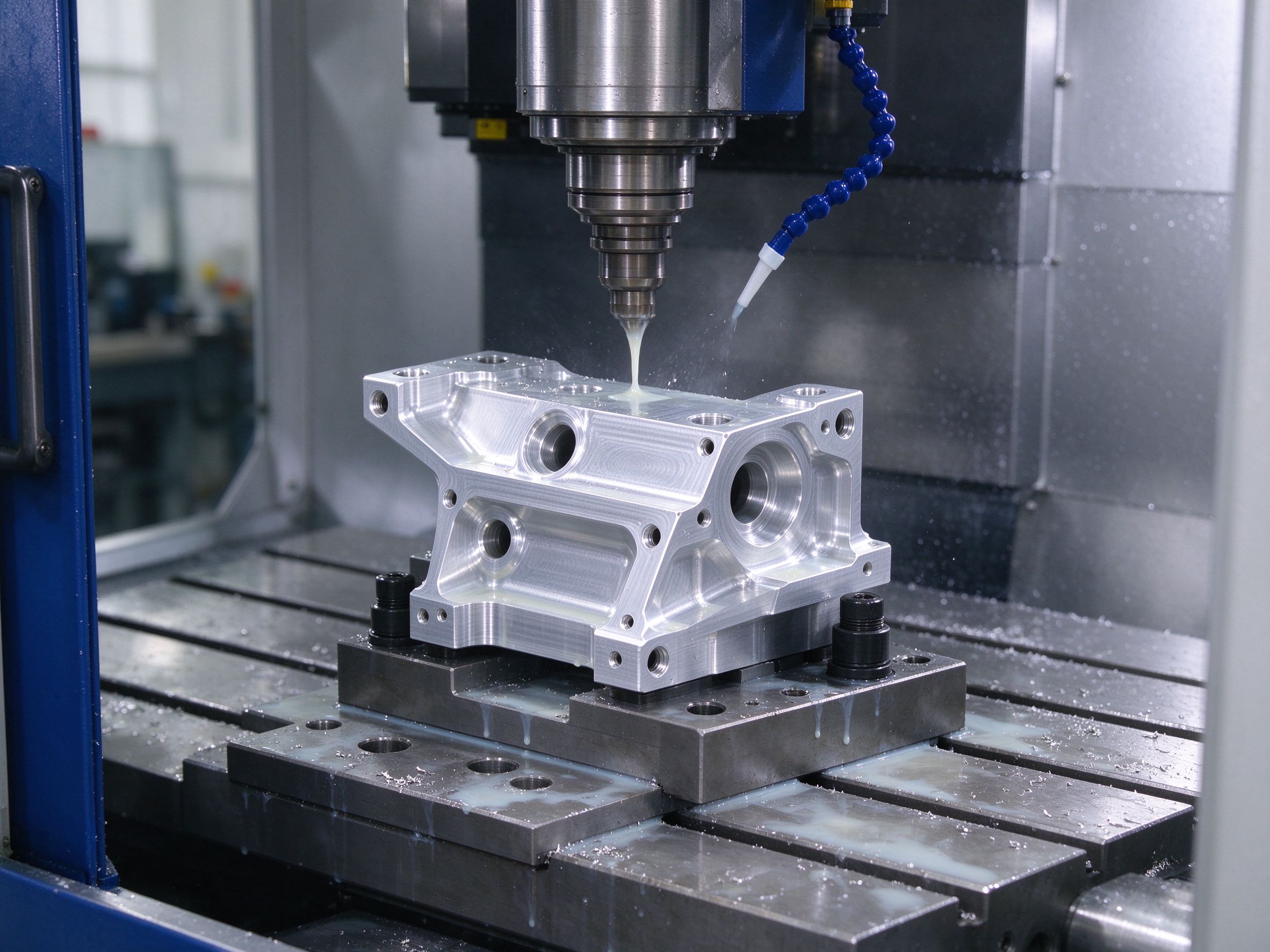
| 3-axis milling | General brackets and support plates | Hole position, plane and slot |
| 4-axis machining | Multi-side holes and circular features | Multi-face datum relation |
| 5-axis machining | Angled and complex instrument seats | Multi-direction features and fewer setups |
| CNC turning | Cylindrical sensor or probe seats and locating sleeves | Concentricity, diameter and fit |
| Drilling and reaming | Locating bores and precision holes | Diameter, position and mating fit |
| Grinding | High-flatness mounting faces where required | Flatness and surface quality |
Reference faces first
Main datum faces and reference holes are identified before fixture and tooling are set.
Control thin walls and arms
Clamping supports thin sections and cantilevered parts to reduce setup shift and machining deflection.
Roughing then finishing
Datum and locating features are finished first, with stress relief considered where the material or section calls for it.
Five-axis capability reduces setup for angled and multi-direction features; it does not by itself set tolerance. Accuracy still depends on fixturing, datum, tool wear, thermal condition, CAM and inspection. Related routes are covered on the 5-axis machining services and CNC turning services pages.
Surface Finish and Environmental Resistance
Raw machined surface
Used where no coating is required and the contact face condition meets the drawing Ra callout.
Clear, black or reviewed hardcoat
For decoration, protection or wear conditions; film thickness and masked features agreed before machining.
Passivation, electropolish, polish, blast
Selected for corrosion condition, cleanability or visual finish on stainless instrument parts.
Machined POM or PEEK
Kept in material condition for insulation and low-friction contact, with surface finish per drawing.
Quality Inspection and Documentation
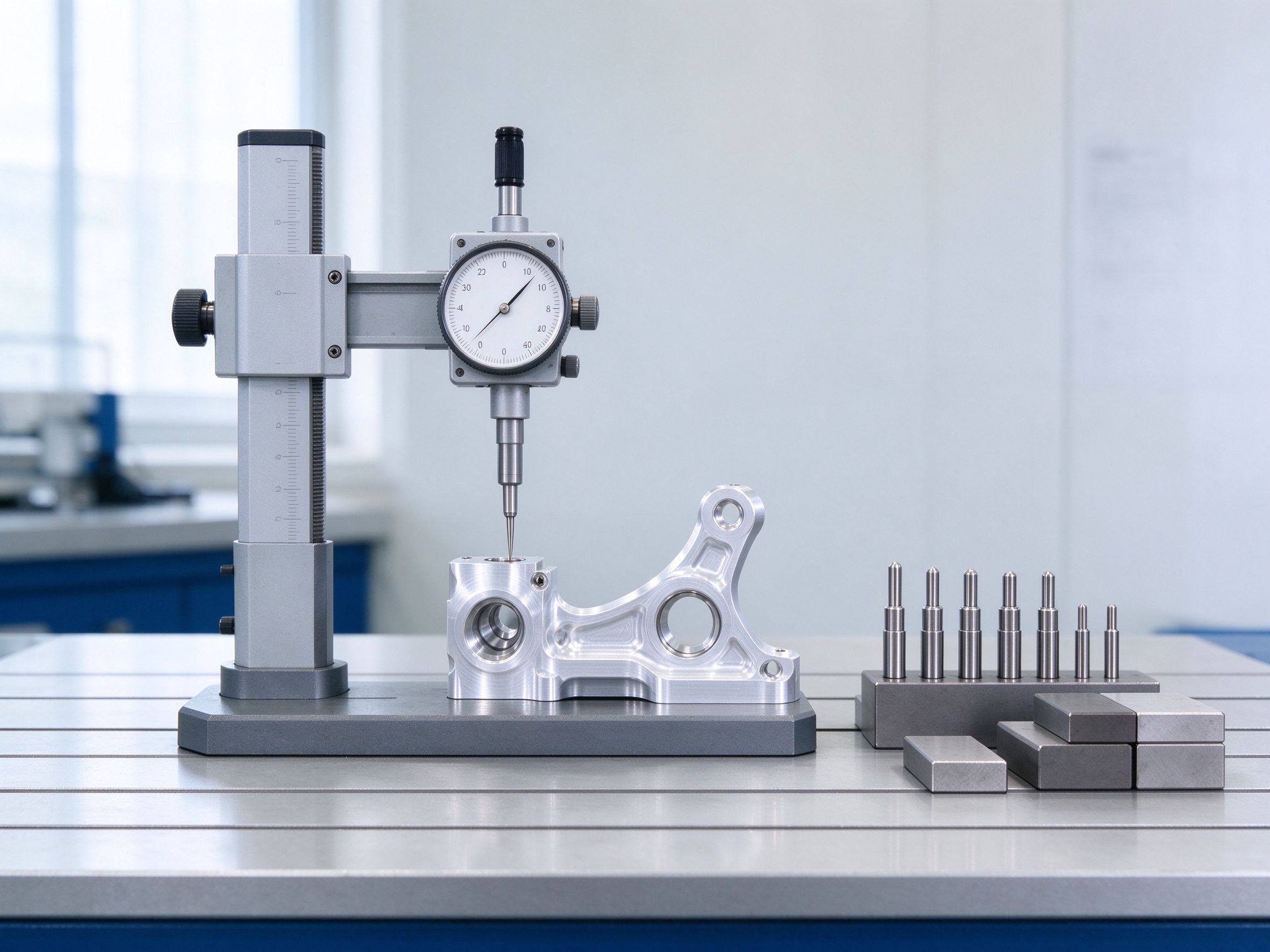
Inspection method matches the claimed tolerance. Review uses a Zeiss Prismo CMM with stated capability for qualified critical features, supported by micrometers, calipers, bore gauges, pin gauges, thread gauges, height gauges and a profilometer where the feature requires it.
| Inspection object | Acceptance content | Tool |
|---|---|---|
| Mounting face | Flatness and seating condition | CMM or height inspection |
| Sensor or probe bore | Bore diameter, roundness and axis | Bore gauge and CMM |
| Hole pattern | Spacing and true position | CMM |
| Dowel pin holes | Pin size and fit | Pin gauge and CMM |
| Side face | Perpendicularity to base datum | CMM |
| Adjustment slot | Width and location | Caliper or CMM |
| Threaded hole | Thread size and engagement | Thread plug gauge |
| Finished contact surface | Roughness and surface quality | Surface roughness tester |
| Document | Value to buyer |
|---|---|
| Dimensional inspection report | Confirms checked key dimensions against datums |
| CMM report | Records complex geometric feature measurements |
| First article inspection | FAI prepared per AS9102 on request before batch release |
| Material certificate | EN 10204 3.1 certificate on request for qualified lots |
| Surface treatment record | Records finish method and reviewed features |
| Certificate of conformance | Declares the part meets the agreed order requirements |
Standard Accessories vs Custom CNC Brackets
The market already supplies standard mounting accessories for common sensor and instrument interfaces: pipe and panel transmitter mounts, clamps for common sensor diameters and fixed-angle mounting kits. These cover many standard installations at low cost. Goldcattle focuses on drawing-based custom mounts where those standard systems do not solve the interface.
Common interfaces and fixed geometry
Pipe or panel mounts for specified transmitter kits, clamps for regular sensor sizes, fixed-angle brackets and catalog hole patterns.
Special interface and alignment requirements
Non-standard housing fit, axis or datum position, several sensors on one integrated plate, special optical or probe mechanism, special material or load case, and low-volume or discontinued-equipment replacement parts.
Prototype to Repeat Production
Review geometry before quote
Drawing, model, material, interface features, adjustment, finish and inspection plan are reviewed for feasibility and risk.
Measure before batch release
Prototype or bridge lot parts are measured against datums and critical features; agreed changes are captured before repeat production.
Same datum and control
Repeat runs follow the approved setup, fixture program, inspection points and records; lot size and annual volume set during RFQ.
Prototype parts support design fit and first-article validation before production tooling or fixture commitment. Delivery condition, fixture concept and repeat-run details are confirmed after drawing review; no fixed lead time or per-unit production price is quoted from a photo alone.
Representative Demonstration
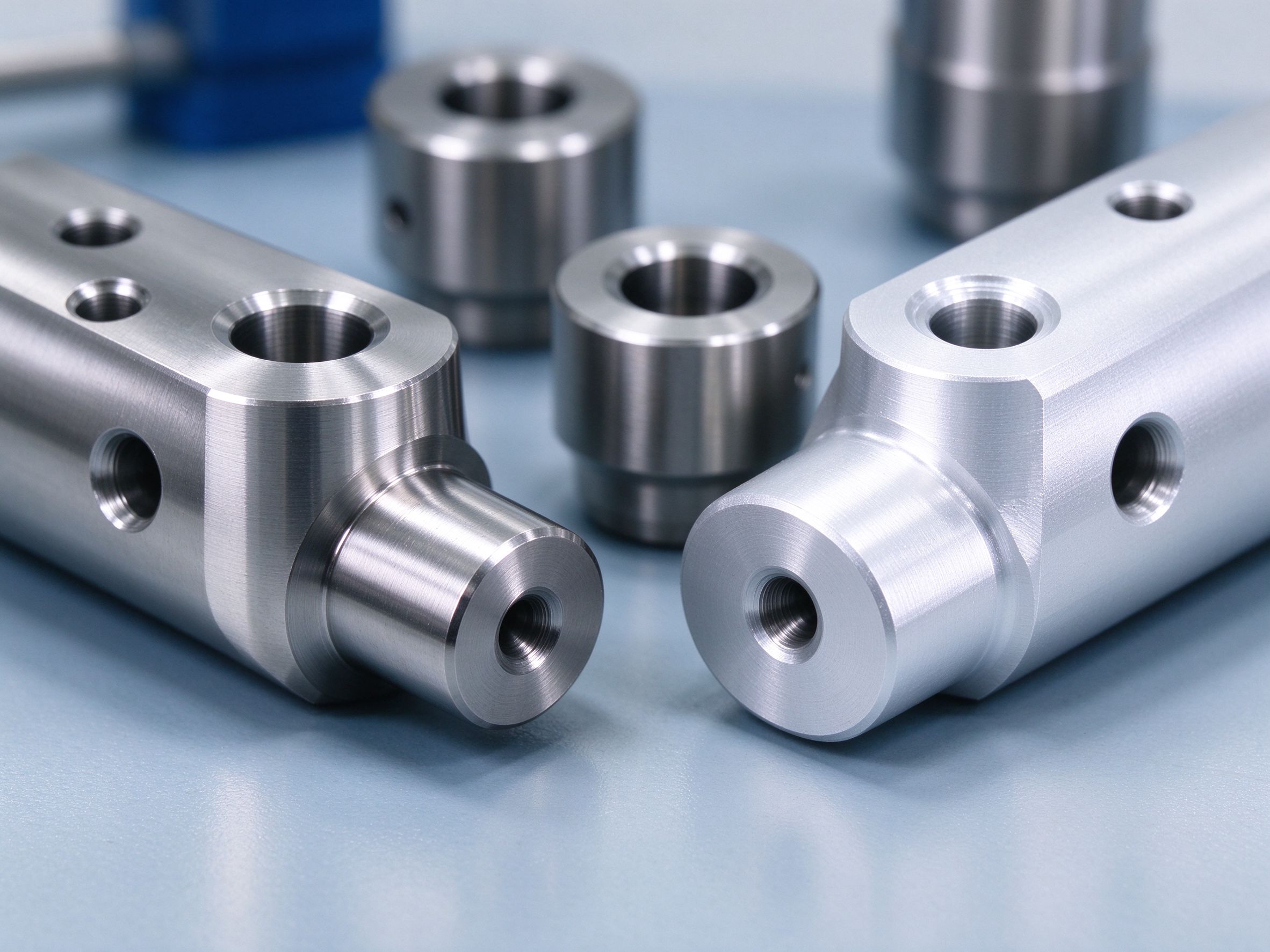
- PartRepresentative probe and sensor holder set
- MaterialAl 6061-T6 and reviewed stainless
- Process3-axis and 4-axis milling, turning, reaming
- Interface featuresClamp bores, datum faces, dowel holes, threads
- InspectionZeiss Prismo CMM, pin and thread gauges
- DocumentsMaterial cert and FAI on request
- VolumePrototype to repeat, confirmed after review
This is an in-house manufacturing demonstration that shows the type of sensor and probe holder we can prepare. It is not a named customer project. Values and feature set describe a representative job type, not a guaranteed accuracy result, customer model or delivery commitment.
RFQ Checklist for Instrument Brackets
The more interface and installation detail is supplied, the more accurately the review can judge process, material, critical features and inspection. The list below maps to what an instrument bracket quote needs.
- Instrument make and model: Sensor, camera, probe, transmitter or gauge reference used for the interface.
- Instrument outline: Body dimensions, housing diameter and mounting location drawing.
- 2D drawing and 3D model: Datums, dimensions, tolerances, GD&T, threads and finish; STEP, IGES, PDF or DWG.
- Mounting interface: Hole pattern, threads, dowel locations, mating faces and bores.
- Functional axis: Sensor axis, optical path or probe direction relative to machine reference.
- Adjustment requirement: Needed angle or position range, locking method and repeat-install plan.
- Cable clearance: Connector size, lead bend radius and access direction.
- Material and finish: Alloy grade, condition, anodizing, passivation or other surface requirement.
- Operating environment: Temperature range, vibration, moisture, chemicals or washdown condition.
- Inspection and documents: CMM report, FAI, material certificate or CoC requirements.
- Quantity: Prototype, first lot and expected repeat or annual volume.
- Delivery target: Destination and required timing, after drawing review confirms feasibility.
Xiamen Goldcattle Plastic & Metal Products Co., Ltd. was founded in 1998 and operates in Xiamen, China, serving North American, European and other global markets with 3, 4 and 5-axis milling and turning under an ISO 9001:2015 quality system. The engineering review checks bracket geometry, mounting features, machining feasibility and dimensional inspection before quotation.
Frequently Asked Questions
What are precision CNC instrument brackets?
Which instrument and sensor mounts can you CNC machine?
Can you make custom sensor mounting brackets to my sensor dimensions?
Can you machine optical and vision instrument mounts?
What materials are suitable for instrument brackets?
How do you control mounting hole position and datum?
What tolerance can instrument brackets hold?
Are CNC machined brackets better than sheet metal brackets?
Can you make adjustable sensor brackets with slots and dowels?
Can you provide anodized or stainless steel instrument brackets?
Do you support prototype and repeat production?
What information do you need for an instrument bracket quote?
Request a Precision CNC Instrument Bracket Quote
Send your instrument mounting drawings, 3D CAD files and assembly requirements. Include the instrument make and model, mounting interfaces, critical datums, material, surface finish and quantity. Our engineering team reviews bracket geometry, mounting features, machining feasibility and dimensional inspection before quotation.
DFM notes, process route and quotation are prepared after the drawing and interface review. General structural aluminum bracket options are listed on the custom CNC aluminum brackets page.