
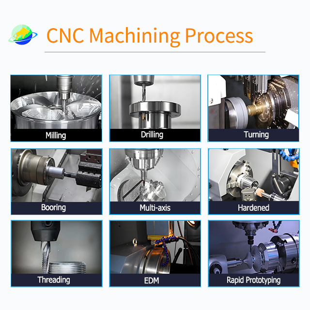
5 Axis CNC Precision Machining for Metal Components
|
Attribute
|
Details
|
|
Processing Technology
|
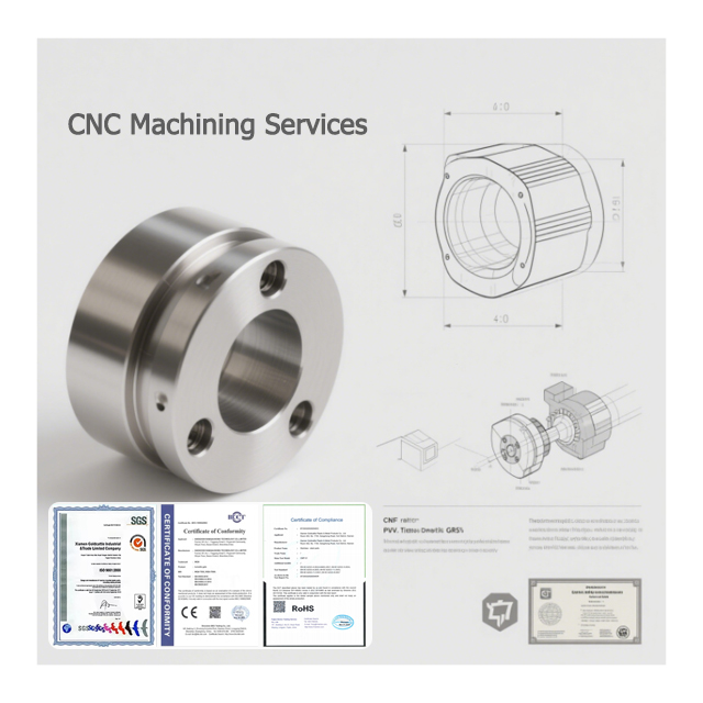
High-precision 5-axis CNC machining, enabling complex surface and multi-dimensional precision processing
|
|
Materials
|
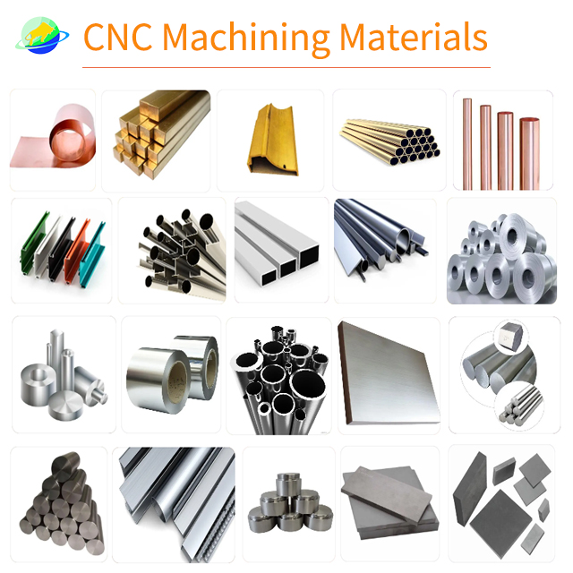
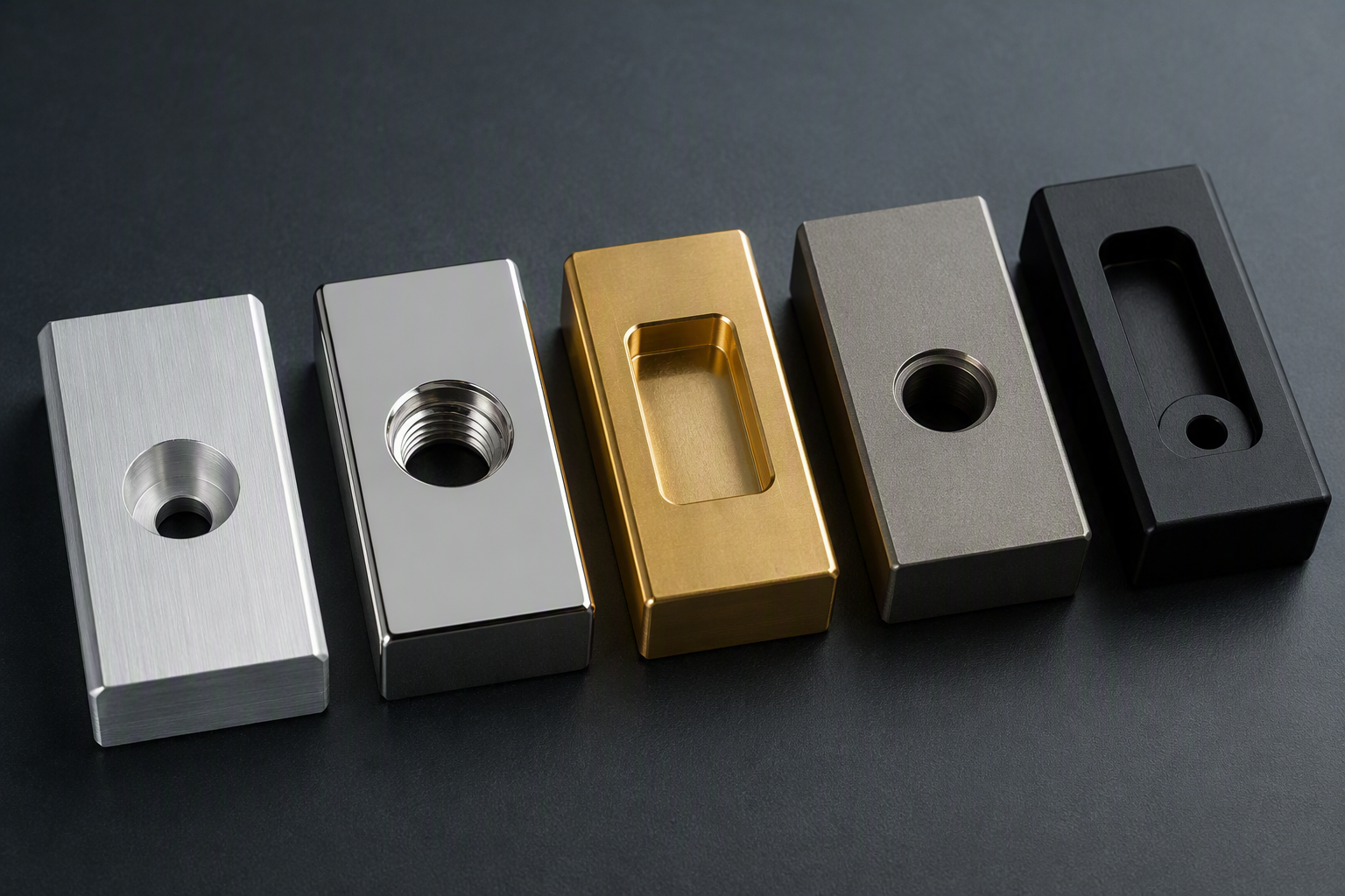
Stainless steel, brass, aluminum, titanium and other metal materials, adapting to different strength, corrosion resistance and lightweight requirements
|
|
Machining Capability
|
Capable of processing precision mechanical components, aerospace structural parts, medical device parts and other complex geometric parts
|
|
Precision Level
|
Dimensional tolerance controlled within ±0.01mm, meeting high-precision assembly and functional requirements
|
|
Surface Treatment
|
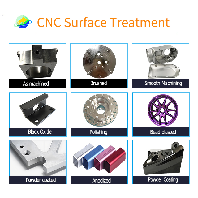
Multiple surface treatment options available: anodizing, electroplating, painting, passivation, etc.
|
|
Machining Range
|
Supports processing from small precision parts to medium-sized structural parts; maximum machining size can be customized
|
|
Application Areas
|
High-end manufacturing sectors: mechanical engineering, aerospace, medical devices, automotive industry, optical instruments, etc.
|
Description
5-Axis CNC Machining for Complex Precision Metal Parts
Not every part needs 5-axis. We select 3-axis, 3+2 or simultaneous 5-axis based on your geometry, tolerance and datum requirements — so complex multi-surface and free-form parts are made with fewer setups and one-datum accuracy you can verify.
1Start from your geometry, not our brochure
5-axis is not "better 3-axis". It changes what is physically possible: a tool that tilts and rotates while cutting holds a single datum across faces a 3-axis machine can only reach by re-clamping. Tick what your part actually has — if most boxes fill, simultaneous 5-axis is the right call.
- Free-form / contoured surfaces (turbine, impeller, blade)
- Features on 4+ unrelated faces of one body
- Deep cavities or steep walls with poor 3-axis tool access
- Compound-angle holes or ports (not just one tilted face)
- Thin walls where each re-clamp adds distortion
- Tight true-position across faces sharing one datum
3-axis is enough
Flat or prismatic parts, simple brackets, plain housings, no undercuts. Lowest cost, fastest setup — we will tell you when this is the right choice.
3+2 positioning
Angled holes, tilted faces, fixed compound positions with no continuous contour. The rotary axis indexes and locks — fewer setups than 3-axis, less risk than simultaneous.
Simultaneous 5-axis
Continuous tool-orientation changes along a curve, deep multi-axis access, one-datum accuracy across many faces. This is where we deploy it — and only when it pays off.
| Part geometry | Recommended process | Why |
|---|---|---|
| Simple prismatic parts | 3-axis CNC | Lowest machining complexity, fastest setup |
| Multiple angled faces | 3+2 CNC | Fewer setups than 3-axis |
| Complex curved surfaces | Simultaneous 5-axis | Continuous tool orientation along the contour |
| Impellers / blades / turbines | 5-axis | Multi-axis surface access no 3-axis can reach |
| Deep cavities / steep walls | 5-axis | Shorter tool, better approach angle, less deflection |
| Multiple datum-critical faces | 5-axis | Repositioning eliminated, one-datum held |
2What we machine on 5-axis
The process earns its place on parts where orientation, access or datum integrity are the constraint. Below is the working envelope and the part families we run — not a catalogue of everything CNC can do.
Geometry & envelope
Simultaneous 5-axis milling of parts up to ~ ⌀500 × 400 mm on our 5-axis centres (larger prismatic work on 3/3+2). Min feature scale down to ⌀0.5 mm drilled holes and 0.3 mm wall where the material and aspect ratio allow. We review each drawing for reach and rigidity before committing a process.
Volume
From a single prototype to production runs. Typical flow: 1–50 pcs prototype / bridge, 50–5,000 pcs low-volume production, with repeat orders supported by retained programs and first-article baselines. MOQ is 1 piece — we quote from the drawing.
Industries we serve
Automotive
Turbocharger impellers, sensor housings, bracket structures.
Medical
Surgical-device fixtures, orthopedic-shaped components, instrument bodies.
Robotics & automation
Multi-face actuator bodies, lightweight arms, custom end-effectors.
Electronics
Heat-sinks, RF housings, enclosures with compound features.
Marine & fluid
Manifolds, valve bodies, pump rotors with deep multi-axis cavities.
Aerospace & UAV
Brackets, ducting, contoured structural parts (drawing & spec driven).
Machinery
Gearbox housings, frames, jigs and fixtures.
Energy
Turbine-adjacent parts, connectors, housing assemblies.
3Materials we cut, and what to watch
5-axis does not change metallurgy — but tool-axis control changes how safely a hard or gummy material can be machined. Below is what we run and the behaviour that actually drives your lead time and cost.
| Material family | Typical grades | Machinability | Key risk on 5-axis |
|---|---|---|---|
| Aluminium | 6061, 6063, 7075, 2024, 6082 | Excellent | Thin-wall spring-back; soft burrs on fine features |
| Stainless steel | 304, 316 / 316L, 17-4 PH | Moderate | Work-hardening at low feed; heat at the tool tip |
| Carbon & alloy steel | 1045, 4140, 4340 | Moderate | Hardening after heat-treat; heavier tool load |
| Titanium | Ti-6Al-4V (Grade 5) | Difficult | Low thermal conductivity → heat at the edge; work hardening |
| Tool & hardened steel | H13, D2, pre-hardened ≤ HRC 50 | Difficult | Tool wear; needs rigid setup and lower MRR |
| Brass & copper | C360, C110 | Good | Sharp edges; burr control on fine geometry |
| Engineering plastics | PEEK, POM, Nylon, ABS, PC | Good | Thermal deformation; clamping marks; static |
4DFM: what makes a 5-axis part run clean
A 5-axis program removes most re-clamping, but it shifts the constraint to tool reach, wall stability and datum choice. These are the rules we apply on review — and the ones worth designing to.
Minimum wall thickness
Aluminium ≥ 0.5 mm, steel ≥ 0.8 mm, titanium ≥ 1.0 mm for stable walls. Below this, vibration and clamp stress dominate — we may recommend 3+2 roughing then finish in one orientation.
Holes & bores
Through and blind holes from ⌀0.5 mm. Compound-angle holes are where 5-axis wins — drill along the surface normal, not by tilting a 3-axis spindle into a weak approach.
Internal corner radius
Minimum practical radius ≈ tool radius. Sharp internal corners need EDM or a relief; on 5-axis we often use a lollipop / barrel cutter to hold a tighter profile with a larger, stiffer tool.
Thin-wall distortion control
Each re-clamp and each cut releases stress. We rough in a soft orientation, stress-relieve lightly if needed, then finish with a tilting tool that holds the wall without squeezing the part.
Datum & GD&T
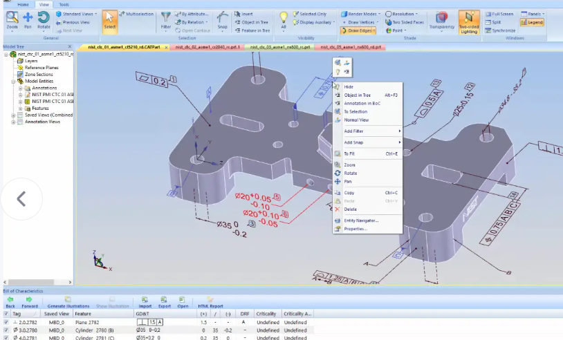
Pick one primary datum that all critical faces reference. 5-axis holds that datum through the whole program — true-position across faces stays tied to one coordinate system instead of accumulating setup error.
Tool-axis & collision
We define lead/tilt angles per region, then run full kinematic simulation (machine + fixture + holder + part) before the first cut. Singularities and over-travel are caught on screen, not on the machine.
5Tolerance bands we hold
Tolerance is a cost and risk lever, not a badge. Tell us what is functional versus cosmetic and we hold the tight numbers only where they matter — everything else runs to a standard band.
| Capability | Typical value | How we hold it |
|---|---|---|
| Standard tolerance | ±0.05 mm | 3-axis / 3+2, general envelope |
| Precision machining | ±0.02 mm | Tightened setup, controlled environment |
| Tight tolerance | ±0.01 mm | 5-axis one-datum, verified finish pass |
| Critical features | down to ±0.005 mm* | CMM-looped, datum-locked, low MRR |
| Surface roughness | Ra 0.4 – 3.2 μm* | Tool choice + finish strategy; finer on request |
| True-position / profile | per GD&T callout | One-datum program, CMM surface-profile report |
6Equipment & capacity
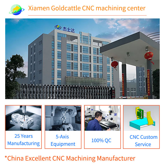
We are a manufacturer, not a trading desk — 100+ machines in-house, no outsourcing of the machining itself. The 5-axis work runs on simultaneous machining centres; below is the configuration we quote against.
| Configuration | Work envelope | Accuracy class | Best for |
|---|---|---|---|
| Simultaneous 5-axis machining centre | ≈ ⌀500 × 400 mm | Positioning ±0.005 mm class | Impellers, contoured & multi-face parts |
| 3+2 indexing 5-axis | Medium / large prismatic | ±0.01 mm class | Angled holes, tilted faces, fixtures |
| 3-axis vertical machining centres | Up to 1000+ mm | ±0.02 mm class | Prismatic, brackets, housings |
| CNC turning (complement) | Small / medium dia. | ±0.01 mm class | Round bodies, shafts, combined mill-turn |
7Quality control, end to end
"CMM-verified" is a step, not a system. For 5-axis parts the risk is not a single dimension — it is accumulated error across faces. Our control runs the full chain below, and you receive the report, not just a promise.
Inspection equipment
Measurement is done with calibrated instruments, with CMM as the anchor for contoured and datum-critical parts.
What you get
Every order ships with the inspection evidence tied to your drawing: material certificate, FAI where required, and a CMM surface-profile / true-position report for critical geometry. Certifications on file: ISO 9001, SGS, RoHS, Rmbond.
8Surface finishes & post-processing
Finish is specified per application — corrosion resistance, appearance, or friction. We coordinate it in-house or with qualified local partners and verify before shipping.
9Real 5-axis work we have run
Three representative programs. Each shows the geometry, the numbers we held, and — importantly — why 5-axis was the right process rather than a 3-axis workaround.
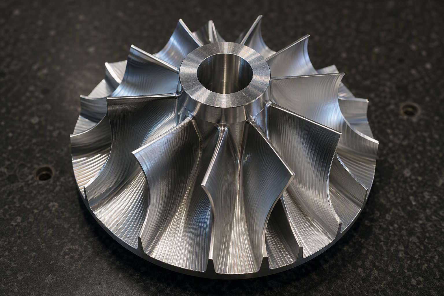
5-axis aluminium impeller
- Material: 7075-T6
- Qty: 20 pcs
- Tolerance: ±0.01 mm
- Finish: Anodized
- Inspection: CMM
- Application: Compressor
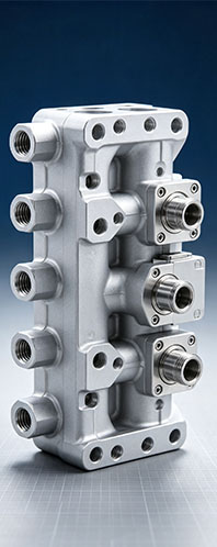
Multi-port hydraulic housing
- Material: 316L stainless
- Qty: 50 pcs
- Tolerance: ±0.02 mm
- Finish: Passivated
- Inspection: CMM + gauges
- Application: Hydraulics
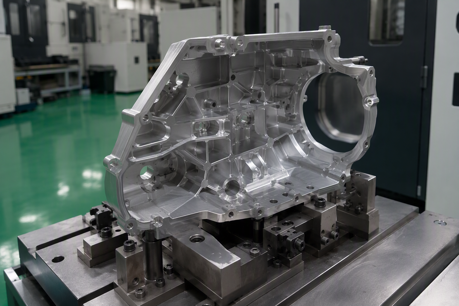
Thin-wall structural bracket
- Material: 6061 aluminium
- Qty: 100 pcs
- Tolerance: ±0.02 mm
- Finish: Bead blast
- Inspection: CMM
- Application: Automation
10Lead time, MOQ & volume
Real numbers from our shop floor — not a placeholder. Lead time starts after drawing review and material confirmation.
Typical lead time
MOQ
1 piece. We quote from the drawing — the more your 2D specifies (datums, critical tolerances, finish), the tighter our number.
What drives cost
Material, part size, complexity, tolerance, quantity, surface finish, inspection level and tooling — not a flat "5-axis rate".
On-time delivery
99.8% on-time across programs, supported by 100+ in-house machines and 24-hour response.
Indicative price (ex-works)
US$40 – $600 / part (prototype)
Simple aluminium parts start near the low end; complex stainless / titanium / tight-tolerance parts sit higher. Production volumes (100+ units) typically cut per-part cost 40–70%.
Budgeting anchor from 2026 market rates for China-based ISO 9001 5-axis shops — not a firm quote. Final price is drawn from your drawing.
Cheaper than you expect
5-axis hourly rates in China run roughly $38–$90/hr vs $120–$250/hr in the US/EU. For prototype quantities, Chinese shops compete most aggressively — often keeping pricing below buyer expectations.
How to lower it
Loosen non-functional tolerances to ±0.05 mm, use standard corner radii, avoid deep narrow pockets, and order in volume tiers. A pre-quote DFM review can flag $20–$200 in avoidable cost per part.
11How to request a 5-axis quote
We return a process recommendation and a price — not just a number. Send the model and drawing; our engineering team checks 5-axis fit, material behaviour, accuracy and inspection before quoting.
Upload files
3D model + 2D drawing. Accepted formats below.
Tell us the spec
Material, quantity, tolerance, surface finish, application, delivery need.
Engineering review
We confirm process (3-axis / 3+2 / 5-axis) and achievability.
DFM feedback
If a change saves cost or risk, we say so before quoting.
Quotation
Transparent quote tied to your drawing and inspection plan.
Production & delivery
Build, inspect (CMM report), pack and ship.
Accepted file formats
STEPSTPIGESX_TSTL2D PDF
12Questions procurement managers ask
Not "what is CNC" — the questions that actually decide whether you send the drawing.
Can you machine 5-axis parts from STEP files?
Yes. We accept STEP, STP, IGES, X_T, STL and a 2D PDF drawing. The 3D model drives tool-path and simulation; the 2D carries the tolerances and datums we inspect against.
What tolerance can you hold on 5-axis parts?
Standard ±0.05 mm, precision ±0.02 mm, tight ±0.01 mm, and critical features down to ±0.005 mm under controlled conditions. Surface roughness Ra 0.4–3.2 μm. We confirm achievability against your drawing before quoting.
Do you offer simultaneous 5-axis or only 3+2?
Both. We select the simplest process that meets the drawing — 3-axis, 3+2 indexing, or simultaneous 5-axis — and tell you which we recommend and why.
What is the maximum part size you can machine on 5-axis?
Up to roughly ⌀500 × 400 mm on our 5-axis centres. Larger prismatic work runs on 3-axis / 3+2 with bigger envelopes. Send the envelope and we will confirm fit.
Can you machine 7075-T6 aluminium and titanium?
Yes. Aluminium (6061/6063/7075/2024/6082) is excellent; titanium Ti-6Al-4V is difficult but routine for us with rigid setup and controlled parameters. Tell us the grade and we confirm.
Do you provide CMM inspection reports?
Yes. Critical and contoured geometry ships with a CMM surface-profile / true-position report tied to your drawing, plus material certificate and FAI where required.
Do you support GD&T drawings?
Yes. Define your datums A/B/C and callouts; our one-datum 5-axis program keeps critical faces tied to a single coordinate system so true-position holds across faces.
Can you make prototypes before production?
Yes. MOQ is 1 piece. Typical prototype lead time is 7–15 days; we retain the program and first-article baseline for repeat and production runs.
What determines the cost of 5-axis machining?
Material, part size, complexity, tolerance, quantity, surface finish, inspection level and tooling — not a flat rate. Tightening only the functional tolerances keeps cost where it belongs.
Can you apply anodizing, passivation or other finishes?
Yes. Anodizing (Type II/III), passivation, plating, powder coating, bead blasting and polishing are coordinated and verified before shipping.