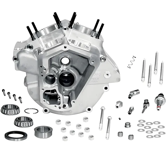
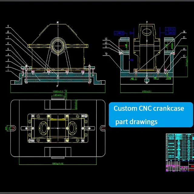
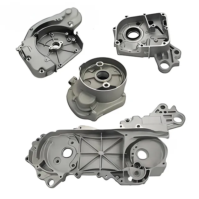
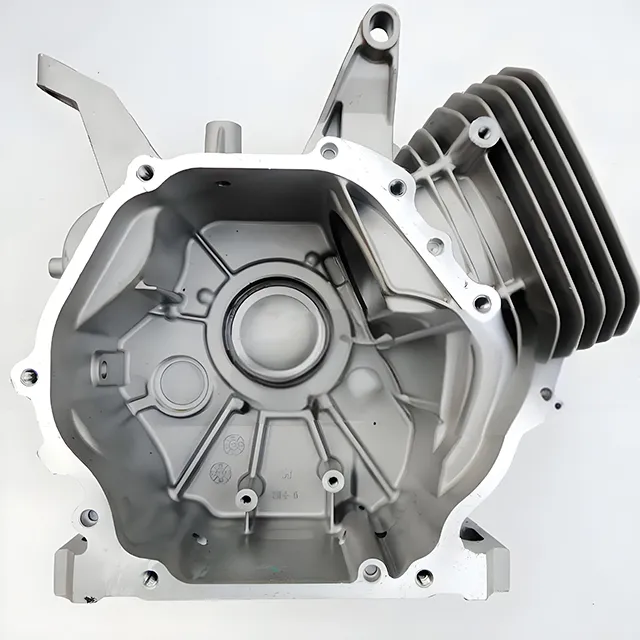
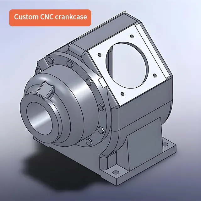
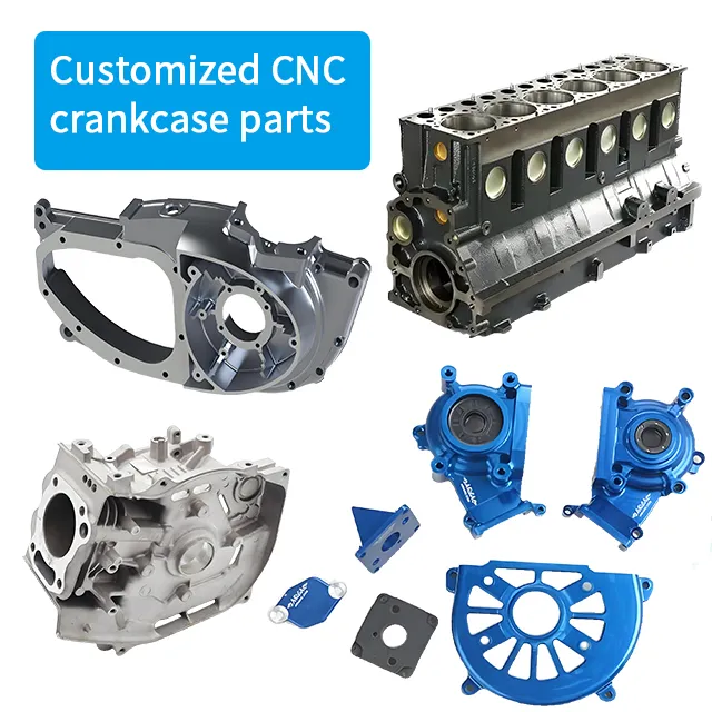
Custom Motorcycle Generator Crankcase | CNC Milling
Discover the next level of performance and efficiency with our custom motorcycle/generator lightweight aluminum alloy CNC milling crankcase assembly. This meticulously crafted component is designed to optimize power delivery and reduce weight, offering a superior power-to-weight ratio for discerning riders and equipment manufacturers. Engineered for precision, durability, and customization, our crankcase assembly is the ultimate upgrade for those seeking to enhance their motorcycle or generator’s engine performance.
Description
Custom CNC-Machined Aluminum Crankcase Assembly
Custom-machined crankcase housings for motorcycle, generator and small-engine applications, manufactured from customer drawings, CAD models or samples.
CNC Aluminum Crankcase Overview
A crankcase is not a decorative housing. It is the structural backbone of the engine: it carries the crankshaft and transmission axes, defines the sealing boundary between the case halves and the cylinder, and absorbs mounting, vibration and internal-pressure loads. When it is machined from a customer drawing, every one of those functions has to survive the translation from CAD to metal — which is why the features below, more than the alloy name, decide whether the part works.
Structural Housing
The case provides structural support and the mounting interfaces for the engine core. Machined faces and bosses carry the loads that hold the engine together and attach it to the frame or generator set.
Bearing / Shaft Alignment
Critical bearing bores and their mating faces determine how the rotating elements sit relative to each other. Bore-to-bore alignment and concentricity are generated from a controlled datum structure, not from luck on the machine.
Sealing Interfaces
Gasket surfaces, sealing faces, the bolt pattern and mating faces between case halves are machined as controlled planes. Flatness and surface condition here are what keep oil inside and contamination out.
Internal Clearances & Features
Internal cavities must leave room for gears, shafts, bearings and lubrication features. Pockets, galleries and reliefs are machined according to the design so the moving elements have the clearance the engineer intended.
Technical Specifications
Parameters are confirmed against your drawing at quotation. We do not publish guessed values for a part we have not yet reviewed.
| Part Type | Crankcase / Engine Housing |
| Manufacturing Process | CNC Milling + secondary operations* |
| Material | Aluminum alloy — grade per customer specification* |
| Material Condition | As specified (e.g. T6 temper, where applicable)* |
| Part Size | Custom per drawing |
| Critical Features | Bearing bores / mounting surfaces / gasket faces / threads |
| Tolerance | Per customer drawing; ±0.005 mm capability on applicable features* |
| Surface Finish | As specified (machined / anodized / bead blasted)* |
| Surface Treatment | Per project requirement* |
| Production Volume | Prototype / Low Volume / Production |
| CAD Format | STEP / STP / IGES / DWG / DXF / PDF |
| Inspection | Per inspection plan — CMM / gauges / profilometer* |
| MOQ | 1 piece |
* Final material, process, tolerance and finishing are confirmed during DFM and quotation based on your drawing.
Why CNC Machining for Aluminum Crankcases?
The honest answer: for many crankcases, casting plus CNC finishing is the better route. CNC earns its place when the design demands complex internal machining, tight alignment between features, or low volume without tooling investment.
Complex Internal Geometry
CNC can machine pockets, bores, mounting features, channels, threaded holes and multi-level surfaces in one programmed sequence — including features a casting alone could not hold to tolerance.
Critical Alignment
Multiple machined faces can be generated under one datum structure, so the positional relationships between bores, faces and hole patterns stay controlled across the part.
Prototype & Low-Volume Flexibility
No complex casting tooling is needed, which suits prototypes, racing development, replacement parts, low-volume production and design iterations.
Material Choice
Billet aluminum or a specified alloy can be used directly, and the material condition (e.g. T6) is selected for the application rather than fixed by a tooling route.
Critical Features Machined on Crankcase Components
These are the features that decide whether a crankcase seals, aligns and assembles. Each one is planned against the datum structure before the first toolpath.
Bearing Bores
Diameter, concentricity, alignment and surface finish. The two halves of a case each carry half of a bore — if the bores are finished in different clamps, the error between them becomes a shim stack or a seized shaft.
Bore · Concentricity · Finish
Shaft / Gear Interfaces
Clearances for the crankshaft, transmission shafts and gears are machined to the design. Bearing seats and their relationship to the case split line are generated in the fewest possible setups.
Shaft · Gear · Alignment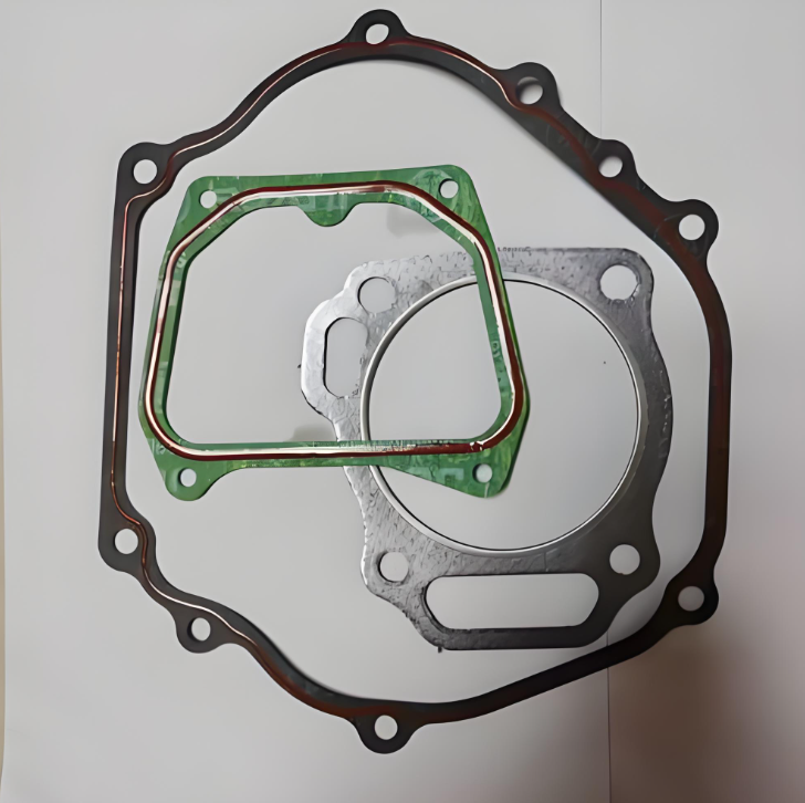
Sealing Surfaces
Gasket faces and cover interfaces are flatness-controlled planes. A face that holds microns at the drawing stage can walk out of tolerance through fixturing distortion — so the workholding decision is made before machining, not after.
Gasket Face · FlatnessThreaded Holes
Mounting, cover and fitting threads are machined to the specified thread standard and depth, and verified with thread gauges where the plan requires it.
Thread · Standard · DepthMounting & Locating Features
Bosses, locating features and bolt patterns give assembly positioning and repeatability. Their position is tied to the same datum structure as the bores.
Datum · Bolt PatternInternal Cavities
Clearance for moving components and oil / lubrication passages are machined where the design calls for them. Tool access into deep cavities is reviewed during DFM.
Cavity · Oil PassageCNC Machining Strategy for Aluminum Crankcases
A crankcase is machined in stages, not in one pass. Each stage protects the datum structure that the next stage depends on.
Main profile and material removal, with cutting strategy planned to limit distortion in thin sections.
Reference faces and features are machined first so every later operation locates from the same structure.
Cavities, bores and galleries are machined with tool access planned during DFM.
Bolt patterns, bosses and threads are generated against the established datums.
Bearing bores, sealing faces and cosmetic surfaces are finished last, in controlled clamps.
Edges, threads and openings are deburred for clean handling and safe assembly.
Fixturing and Datum Strategy
Crankcases contain multiple functional faces and intersecting bores, so datum selection and workholding strategy are what keep positional relationships between features under control.
Primary locating faces and reference features are machined first, establishing the datum structure for all later operations.
Later operations locate from the established features, not from raw stock, so positional error does not accumulate.
Thin-wall sections are supported with appropriate workholding to hold flatness and bore geometry during finishing.
Production batches repeat the same clamping sequence so every part is machined from the same relationship to the datums.
Where case halves carry a shared bore, the finishing strategy is planned to protect bore-to-bore alignment across the split line.
The datum and fixturing plan is defined at DFM so the machinist, inspector and customer are looking at the same reference system.
Aluminum Alloy Selection
| Alloy | Typical Consideration |
|---|---|
| 6061 | General-purpose machining and structural applications; good machinability and anodizing response |
| 7075 | High strength-to-weight applications |
| 6082 | Structural machining applications |
| Other alloys | Project-specific requirements |
Surface Finishing Options
| Finish | Purpose | Note |
|---|---|---|
| CNC machined finish | Functional, lowest cost | Tool marks visible; roughness per process |
| Anodizing | Corrosion protection + color | Adds oxide layer — critical bores and mating faces need dimensional consideration* |
| Bead blasting | Uniform matte appearance | Texture change; edges can be affected* |
| Polishing | Smooth / reflective surface | Removes material* |
| Powder coating / chemical treatment | Durable color or protection | Adds thickness where applied* |
Final surface treatment depends on corrosion requirements, appearance, dimensional impact and engine environment. Confirm the finish with our team — see the CNC Surface Finishing Guide for the full material-to-finish matrix.
CNC Machining vs Casting for Crankcase Production
Many crankcases are naturally casting-plus-CNC parts: casting forms the complex thin-wall structure, and CNC finishes the bearing bores, gasket surfaces and mounting features. We are not selling CNC for its own sake — we are helping you choose the route that fits the volume and the design.
| Requirement | Billet CNC | Casting + CNC |
|---|---|---|
| Prototype | Excellent | Tooling required |
| Low volume | Strong | Higher tooling burden |
| High volume | May be expensive | Often more economical |
| Complex thin walls | Limited by machining | Strong |
| Design changes | Easy | Mold / tool changes |
| Material removal | Higher | Lower |
| Tooling investment | Low | Higher |
| Best fit | Prototype / low volume | Medium / high volume |
Choose the Right Crankcase Manufacturing Route
CNC From Billet
- Prototypes
- Development engines
- Low volume
- Frequent design changes
Casting + CNC
- Larger production volume
- Complex thin walls
- Material efficiency
- Stable design
Hybrid
- Structure formed by casting
- Critical surfaces finished by CNC
- Best of both routes
What Can Be Customized?
| Feature | Customization |
|---|---|
| Overall Geometry | Customer CAD / drawing |
| Material | Specified aluminum alloy |
| Bearing Bores | Custom |
| Mounting Holes | Custom |
| Thread Specifications | Custom |
| Internal Cavities | Custom |
| Gasket Interfaces | Custom |
| Logo / Marking | Where required |
| Surface Treatment | Project-specific |
| Production Volume | Prototype to production |
Made From Your CAD, Drawing or Sample
We produce according to the drawings or samples. The drawing is the contract — everything machined is checked back to it.
From First Part to Approved Production
First Article Inspection (FAI) is available for qualified projects, aligned with AS9102 where required.
Quality Inspection for CNC Crankcase Components
The inspection plan follows the drawing. We do not claim every feature is measured on every order — critical features are verified with the method the plan requires, and you tell us what needs documenting.
| Inspection Item | Typical Method |
|---|---|
| Bore Diameter | Bore gauge / CMM |
| Position | CMM |
| Flatness | CMM / surface measurement |
| Thread | Thread gauge |
| Surface Roughness | Profilometer* |
| Visual Defects | Visual inspection |
| Overall Geometry | CMM / optical measurement |
* Inspection methods are applied per the agreed plan, using equipment available at Goldcattle (including Zeiss CMM). Dimensional reports and material certificates are provided where specified.
What Dimensions Matter Most on a Crankcase?
These are the dimensions our engineers watch first. Tolerance values come from your drawing — not from a catalog page.
Bearing Bore
Drives bearing fit and shaft alignment.
Cylinder / Mounting Interface
Drives engine assembly.
Gasket Surface
Drives sealing.
Shaft Center Distance
Drives gear / shaft alignment.
Bolt Pattern
Drives assembly.
Internal Clearance
Drives moving components.
CNC-Machined Crankcase Case Study
A working example in the format we use for real projects. Share your drawing and we will return a project-specific review — we do not publish invented yield or tolerance figures.
| Project | Motorcycle / generator crankcase* |
| Material | Aluminum alloy, per spec* |
| Starting Stock | Billet or casting, per route* |
| Manufacturing Process | CNC milling (3/4/5-axis) + secondary* |
| Critical Features | Bearing bores, gasket faces, mounting holes* |
| Inspection | CMM / dimensional per plan* |
| Surface Treatment | Per project requirement* |
The case required thin-wall machining while maintaining dimensional stability around multiple openings and bearing bores.
Engineering SolutionMachining sequence and workholding were optimized so critical bores and gasket faces stayed on the datum structure during finishing.
ResultConsistent geometry and surface condition across the batch, verified by dimensional inspection.
* Project-specific values are confirmed from your drawing at quotation. Related verified portfolio result: 6061-T6 aluminum housings produced at 20,000 pieces with ±0.02 mm bore concentricity and zero rejects in final inspection — see CNC Machining Services.
Applications
Motorcycle Engines
Racing motorcycles, performance motorcycles, custom engines, prototype engines.
Generator Engines
Gasoline generators, compact power equipment.
Small Engine Development
Prototype engine housings, low-volume engine programs.
Motorsport
Low-volume, design-intensive engine programs where quick iteration matters.
Custom Crankcase Key Capabilities
Precision-Machined Functional Interfaces
Focus on bores, mounting features and mating surfaces — the interfaces that make the part work, not just look machined.
Custom Engine Geometry
Produced from customer CAD or drawings, with geometry adapted to the engine architecture.
Aluminum Alloy Construction
Alloy and material condition specified according to project requirements.
Complex Internal Features
Pockets, bores, threads and other geometry can be machined according to the design.
Controlled Surface Finish
Machined or post-processed according to the application requirement.
Inspection Support
Dimensional inspection and documentation available according to project requirements.
Why Source Custom Crankcase Components From Goldcattle?
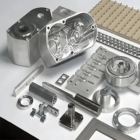
The same 100+ machine fleet that runs this crankcase work runs housings, enclosures and precision components across industries — with one quality system and one inspection standard.
Frequently Asked Questions
What material is suitable for a CNC-machined crankcase?
Aluminum alloys such as 6061 and 7075 are common for machined crankcase and engine-housing work, depending on the load case, the casting or machining route, thermal behaviour and cost. The grade should be confirmed against the drawing and application at quotation.
Can you machine a motorcycle crankcase from billet aluminum?
Yes. CNC machining from billet aluminum suits prototypes, development engines, low-volume production and frequent design changes, where tooling investment is not justified.
Can you manufacture a crankcase from a customer drawing?
Yes. We manufacture from customer-supplied 3D CAD models, 2D engineering drawings or, for reverse-engineered parts, physical samples.
What aluminum alloys can be used?
Common options include 6061 and 7075 aluminum and other project-specific alloys. Confirm the grade and material condition with our team before quoting.
Can you machine bearing bores and mounting interfaces?
Yes. Bearing bores, mounting faces, threaded holes and gasket surfaces are machined as critical features and verified against the drawing.
Can you maintain tight tolerances on crankcase components?
Precision capability is ±0.005 mm on applicable CNC features. What a specific crankcase can hold depends on material, geometry, feature size and inspection requirements, so the final tolerance is confirmed during DFM.
Can you provide CMM inspection?
Yes. Dimensional inspection with CMM and other precision equipment is available, with dimensional reports provided according to project requirements.
Do you offer anodizing or other surface treatments?
Yes. Depending on the material and requirement, options include anodizing, bead blasting, polishing and other treatments. Anodizing adds an oxide layer, so critical bores and mating faces are considered for masking or machining allowance.
Is CNC or casting better for crankcase production?
It depends on volume, geometry and design stability. CNC from billet suits prototypes and low volume; casting plus CNC finishing becomes more economical at higher volume or for complex thin-wall structures. We will recommend the route for your part rather than selling one process.
Can you manufacture prototypes before production?
Yes. MOQ is 1 piece, so a prototype can be machined, inspected and approved before a production batch.
What CAD files do you need for a quote?
A 3D model in STEP or IGES plus a dimensioned 2D drawing (PDF, DWG or DXF) is recommended for the most accurate DFM review and quotation.
Request a Custom CNC Crankcase Quote
Send the drawing and the project context — the more complete the RFQ, the more useful the DFM review.
- Name / Company / EmailWho we are quoting and who to contact
- ApplicationMotorcycle, generator, small engine, other
- Part MaterialAluminum grade or material condition
- Annual Volume & Prototype QuantityQuantity targets for both stages
- CAD / Drawing UploadSTEP / IGES / 2D drawing, or sample reference
- Required ToleranceCritical dimensions and GD&T callouts
- Surface Finish & TreatmentAppearance and treatment requirements
- Inspection RequirementsCMM report, material cert, FAI, etc.
DFM feedback on wall sections, tool access and critical tolerances
Material and manufacturing-route recommendation
Production quotation with estimated lead time
Confirmation of inspection and documentation scope
Related Services & Guides
Have a Crankcase to Machine?
Send your CAD, drawing or sample with the application details. Our engineers will review the critical features, confirm the material and route, and come back with a DFM-backed quotation.