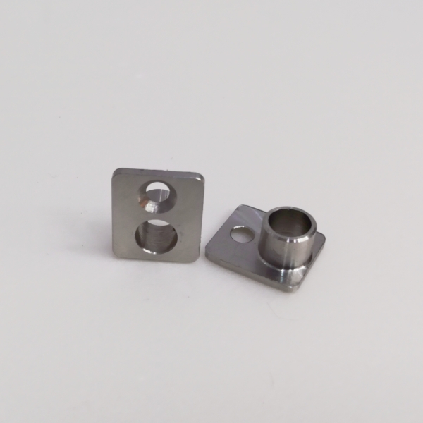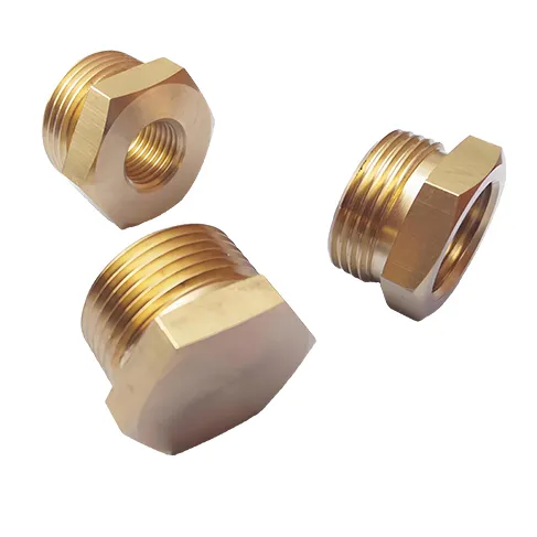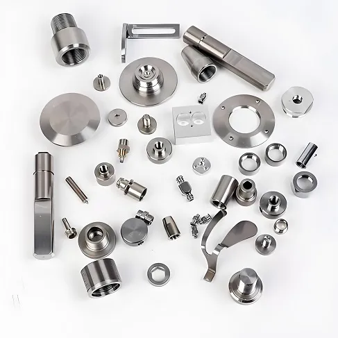
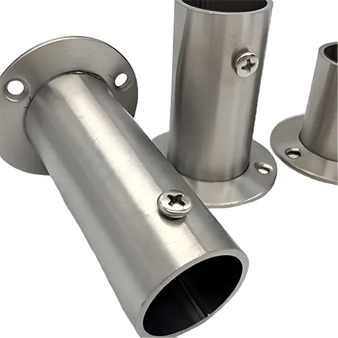


CNC Stainless Connecting Tubes | ±0.005mm, 316L
Product Name : CNC Stainless Steel Connecting Tube
Material : Stainless steel
Service : CNC turning/milling
Surface treatment : As per customer’s requirement
Size : Customized
Application : Wide range, according to customer’s requirement
QC : 100% Quality Control
Certification : ISO9001
Customization : OEM
Tolerance : +/-0.005mm
Description
Custom Stainless Steel Connecting Tubes
A connecting tube is not a fitting with a tube attached. The tube is the body: its outside diameter is what the clamp grips, its wall is what deforms to make the seal, and its axis is the datum every machined end is measured from. Most joint failures we are asked to look at are dimension errors that started with the tube being treated as a stock size.
- 304 / 304L · 316 / 316L
- End geometry to drawing
- Passivation to ASTM A967
- Mill certificate + dimensional report
What This Part Is, and What It Is Not
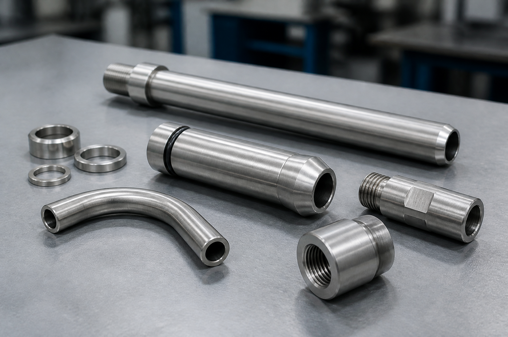
It is a length of austenitic stainless tube with one or both ends cut, bored, turned, threaded, grooved or beveled to a drawing — a component whose function exists entirely at its two ends. Whether it is called a connecting tube, a tube connector or a tube adapter, the part is defined by its ends: everything between them is tube. Between them it is a purchased tube; at the ends it is a machined part, and the two are held to completely different sets of tolerances.
That split is the whole subject of this page. A drawing that applies one blanket tolerance to the entire component is describing something that cannot be manufactured, because the tube body cannot be held to a machining tolerance at all. It arrives from a mill at the mill's OD and wall tolerance, and no amount of turning on the outside of a 1.5 mm wall turns it into a precision bore.
1Industrial equipment OEMs
A tube that carries fluid between a pump, a valve block and a sensor inside one machine. The recurring problem is that the drawing was drawn from the ports inward, so the tube length and both end angles have to absorb the accumulated position error of everything it connects.
Usually asks for: port coordinates, end angle, insertion depth, assembly sequence.
2Fluid system and instrumentation builders
Small-bore tube runs where the joint is a ferrule or a clamp and the seal is made by controlled deformation of the tube itself. Here the tube OD tolerance and the surface condition along the grip length matter more than anything the machinist does.
Usually asks for: tube OD tolerance class, wall, surface condition, ferrule compatibility.
3Food, beverage and pharma equipment
Product-contact tube with a hygienic requirement: a bore that drains, no crevice at the joint, a surface finish the cleaning cycle can reach, and material traceability back to the heat.
Usually asks for: 316L, Ra target, 3.1 certificate, weld and finish records.
4Distributors and MRO buyers
Repeat supply of a part that already exists in the field, often with no drawing — only a sample, or a part number from a supplier who has stopped making it. Reverse-dimensioning the sample is the first operation.
Usually asks for: sample replication, batch traceability, packaging, repeatability.
The Clamp Is Bought. The Tube End Is Made.
In a clamp-type or ferrule-type joint, the element that grips the tube is a purchased component with its own catalog tolerances. What is not purchased is the tube end that element grips — and that is where the joint either works or does not. The ferrule closes onto the tube's outside diameter over a defined grip length, so three properties of the tube end become functional dimensions: the OD at the grip zone, the wall behind it, and the surface the seal travels over.
A tube connector is therefore a two-supplier part, and the join between the two is the drawing. This is why a supplier can machine a connector body to ±0.01 mm and still ship a joint that leaks. The body was right. The tube end it was matched to was not measured against the same assumption.
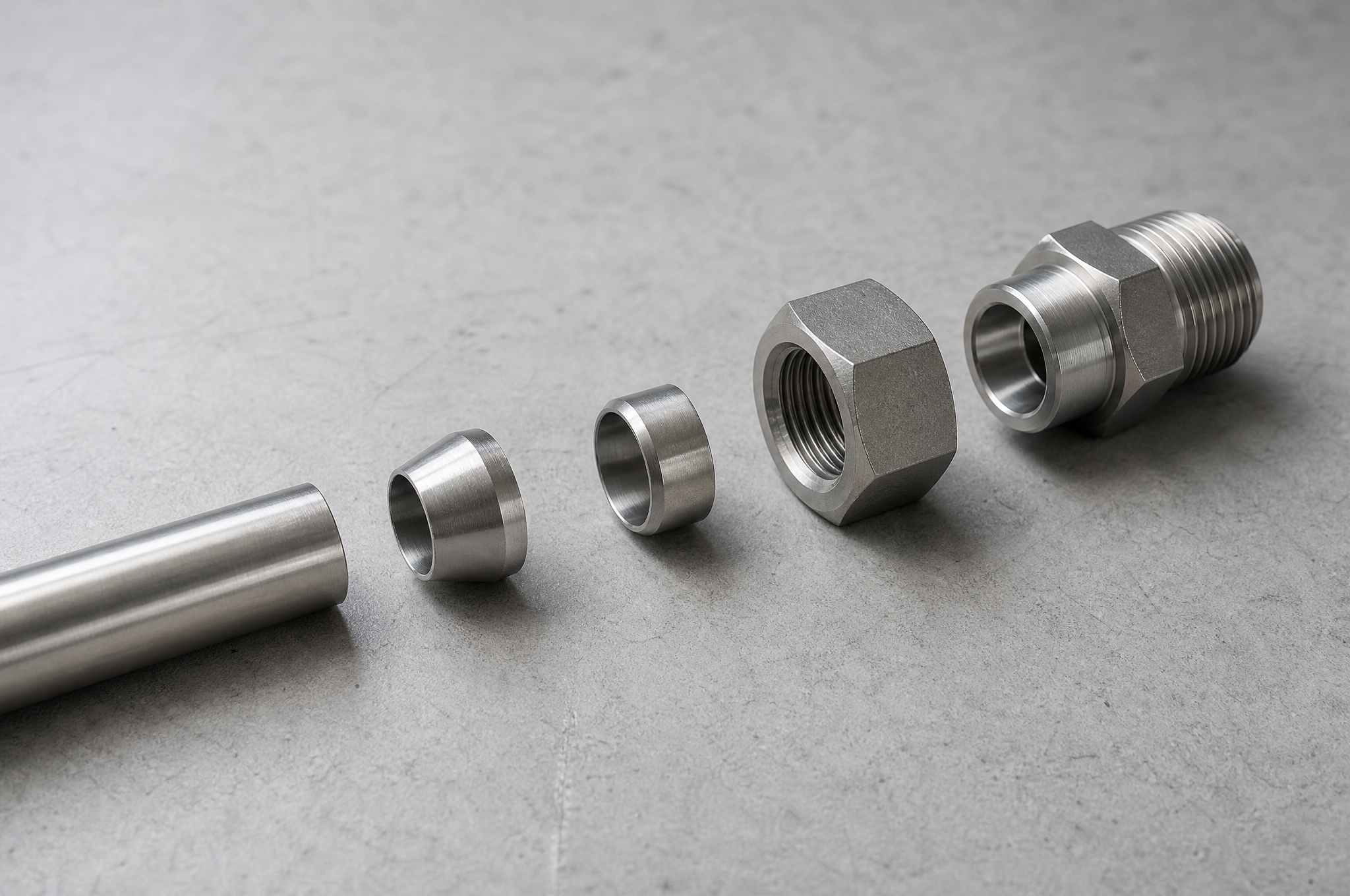
| End form | What carries the seal | What the drawing has to fix |
|---|---|---|
| Plain end, weld preparation | Fusion at the joint; there is no elastomer and no clamp load | Bevel angle, root land, wall at the bevel, cleanliness and post-weld passivation |
| Step or shoulder for a clamp collar | Radial compression of the tube onto a collar or ferrule | Step diameter and its tolerance, step length, undercut radius, OD runout behind the step |
| O-ring groove | Elastomer compression in a machined groove | Groove width and depth, groove position from the end, base radius, surface finish in the groove |
| External thread | The thread itself on a tapered form; a shoulder washer or O-ring on a parallel form | Thread form and standard, effective length, undercut, wall remaining under the root |
| Internal thread in a thick-wall end | Same as above, with the pressure acting on the bore | Thread depth, counterbore, wall outside the thread, concentricity to the bore |
| Flared cone (37° or 45°) | Metal-to-metal contact between the cone and the mating seat | Cone angle, seat diameter, concentricity to the bore, finish on the cone face, wall at the flare |
| Machined flange or collar | Gasket compression between two faces | Face flatness, squareness to the axis, bolt pattern and its position from the end |
| Custom geometry | Whatever the drawing defines | Every dimension, plus the datum the inspector should measure from |
Two of these rows carry a warning that is worth stating on their own. A thread cut directly into a thin tube wall is a compromise: the root of an NPT-form thread already consumes a large share of a 1.5 mm wall, and what remains is a land with no margin for corrosion allowance or for a second assembly. Where a drawing shows a thread on a thin tube, the practical answer is usually a thicker-wall section, a welded collar, or a threaded insert — and that is a change to raise at drawing review, not at the machine. And a parallel thread cannot seal on its own thread. An NPT taper seals by flank interference with a sealant; a BSPP parallel thread seals on a washer or an O-ring against a shoulder, and its thread is only there to clamp. Confusing the two is one of the most common drawing errors in this product family, and it produces a part that is dimensionally perfect and permanently wet.
Tube Stock Is a Specification, Not a Size
The tube is half the component and it is the half that arrives with someone else's tolerances attached. “316L tube, 12 × 1.5” does not define a part, because two mills will deliver that description with different OD tolerance classes, different wall tolerances, different straightness and different surface condition — and at least one of those differences will move the joint.
| Specification | What it covers | Where it shows up in a connector |
|---|---|---|
| ASTM A269 | Seamless and welded austenitic tube for general service | The usual starting point for instrument and fluid tube; its OD and wall tolerances set the bore you can machine around |
| ASTM A213 | Seamless ferritic and austenitic tube for boiler, superheater and heat-exchanger service | Higher-temperature and pressure duty; the wall is specified for a design pressure, not for machining convenience |
| ASTM A249 | Welded austenitic tube for boiler and heat-exchanger service | Welded rather than seamless, with a weld seam that has to be considered if the end is to be machined thin |
| ASTM A270 | Sanitary tube | Product-contact duty; brings its own ID finish and cleanliness expectations, and tolerances that differ from A269 |
| ASTM A554 | Welded mechanical tube | Structural and decorative use; typically the loosest of these on OD and wall, and a poor basis for a sealing joint |
These are not interchangeable. A part drawn against A269 and quoted on A554 stock is cheaper, arrives sooner, and can miss the ferrule grip by more than the ferrule can absorb. The same applies to the material certificate: an EN 10204 3.1 certificate carries specific test results and is issued with the mill's independent inspection sign-off; a 2.2 certificate states compliance without those results. If the quality plan calls for 3.1, that requirement has to reach the tube purchase order, because it cannot be created afterwards at the machine.
Straightness belongs in the same conversation. A tube that bows over its length cannot be held at one end and machined at the other with the far end on axis — the bow shows up as runout at the end that was not supported. Tube straightness is a mill property, so if the drawing calls for a total runout that is tighter than the stock's straightness can support, the answer is either to machine between supports or to specify straighter stock. Both are decisions made before quotation, not during it.
Machining a Wall, Not a Billet
Turning a connector body from bar is a forgiving operation: the material is solid, the clamping force is trivial against the section, and deflection is a second-order concern. Turning the end of a thin tube inverts all three conditions. The part is a shell, the clamping force approaches the force that ovalises it, and the cutting force pushes the wall away from the tool before the tool has finished cutting.
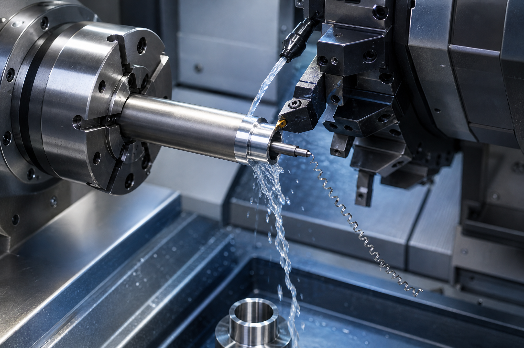
| Operation | What it produces | How a thin wall makes it harder |
|---|---|---|
| Facing and squaring the end | The reference face every axial dimension starts from | A short, unsupported end deflects under the tool; the face ends up crowned, and every length measured from it inherits the error |
| OD turning at the grip zone | The diameter the ferrule or clamp closes onto | Clamping pressure ovalises the tube, so the diameter cut while held is not the diameter released — and the error is not round |
| Boring the ID | Flow bore, and concentricity to the OD | Boring bar deflection grows with depth; the bore tapers and drifts off the tube axis rather than the chuck axis |
| Threading | The clamping or sealing interface | Root depth against remaining wall; the thread crest can lift the wall outward if the section is thin |
| Grooving | O-ring seat or clamp location | A groove removes the stiffest band of the section; the tube can deflect into its own groove |
| Flaring or forming a cone | The metal-to-metal seat | The form is produced by displacing material, so wall thickness at the cone is not the wall you started with |
| Parting off | Overall length, and the second end | The burr at the bore is inside the part; a burr removed by hand changes the length and the bore edge in one operation |
Four consequences that show up on the part
1Ovality that measures as good diameter
A two-point micrometer across an oval bore reads the average of two axes. Hold it at 45° to the clamp jaws and it reports a dimension the part does not have all the way round. The ferrule feels the difference even when the inspection sheet does not.
Fails when: the grip-zone OD is inspected with a two-point gauge only, on a part held in a three-jaw chuck.
2Bore drift along the length
A boring bar entering eight diameters deep follows the path of least resistance. If the tube is not straight, the bore follows the bow instead of the axis, and the two ends are no longer coaxial with each other even though each is concentric with the tube near it.
Fails when: concentricity is checked at one end only.
3Chatter that becomes a leak path
A wall that rings under the tool leaves a banded surface at exactly the place a seal has to travel. The dimension can be inside tolerance while the finish is not, and a ferrule closing onto a chattered band has a circumferential leak path built into it.
Fails when: the drawing specifies the diameter and omits the surface requirement on the sealing band.
4Length that moves after deburring
Overall length is usually measured before the bore burr is removed, because the burr is inside and out of sight. Hand-deburring then takes 0.05–0.2 mm off one end and the part arrives short at the assembly, in a way that is invisible on the inspection sheet.
Fails when: length is inspected before deburr, or deburr is left to a manual operation with no length check after it.
The countermeasures are unglamorous and they are the reason this work is quoted as a process rather than a rate: a collet or an expanding mandrel instead of a three-jaw chuck on thin sections, a support or a follower where the overhang is long, a boring strategy that steps out instead of plunging, and a deburr operation that is followed by a length check rather than preceded by one.
The Datum Is the Tube Axis — and the Tube Bends
On a machined connector body the datum question is easy: the part is short, stiff and can be held in one setting, so the bore, the thread and the seal face are coaxial because they were cut without reclamping. A connecting tube is long, compliant and has to be machined from both ends, which means the datum has to be transferred and the transfer is where the error enters.
Three statements, in the order they cause trouble:
- Runout at one end says nothing about the other. A tube indicated at the headstock and machined at the tailstock end can have that end perfectly concentric to the tube surface next to the chuck while the two functional ends are visibly out of line. The measurement that matters is between the two ends, not to the nearest surface.
- Reclamping moves the axis. Turning the part around to machine the second end re-establishes a new axis from a different section of tube. Any bow, any ovality from the first clamp, and any variation in wall is now baked into the relationship between the two ends.
- Length is not independent of alignment. When both ends are machined from a common reference, the length and the end squareness come out together. When they are machined from two references, a squareness error at one end shows up as a length error at the other, and the assembly absorbs neither.
How the datum is actually held
| Method | What it guarantees | When it is the right choice |
|---|---|---|
| One setting, part held at one end | All features at that end share an axis; the far end is unconstrained | Short parts, or parts where only one end is functional |
| Two operations with a soft collet on the finished end | The second end is machined from the first, so the two ends agree with each other | Most two-end tubes, provided the finished end can be held without marking it |
| Between centers or with a plug support | The axis is the tube's own center line over its whole length | Long tubes, or a drawing with a total runout between ends |
| Machined from bar, then the tube welded on | Each end is a stiff machined body with its own datum | Ends that carry threads or seats too demanding for the wall of a tube |
Passivation, Pickling and Electropolishing Do Different Jobs
Stainless tube arrives passive and machining takes that away locally. Cutting tools, brushing, blasting media and handling all transfer free iron onto the surface, and free iron is what rusts first. The three finishes below are not grades of the same treatment, and quoting one when the requirement is another is a common and expensive substitution.
| Treatment | What it removes or does | What it does not do | Effect on dimensions |
|---|---|---|---|
| Passivation, ASTM A967 | Dissolves free iron contamination from the surface and restores the passive film chemically | Does not remove heat tint, scale, weld discoloration or embedded particles; does not smooth a surface | None measurable — it is a chemical treatment, not a stock-removal one |
| Pickling, per ASTM A380 practice | Removes scale, heat tint and the chromium-depleted layer beneath it | Does not produce a polished or controlled-Ra surface; leaves a matte etch that must itself be passivated afterwards | Removes a thin layer uniformly; not a dimensioning process, but it does change the surface you measure roughness on |
| Electropolishing | Levels the surface at a microscopic scale and removes embedded contamination along with it | Does not fix a scratch, a chatter band or a burr — it reveals them more clearly | Removes material, tens of micrometers per cycle depending on the cycle and the alloy, so tight features must be dimensioned with the allowance |
| Mechanical polish or brush | Changes the surface topography; used to control Ra on visible or product-contact surfaces | Does not passivate; a polished surface can be more contaminated than an untreated one because the operation introduces iron | Can move an edge radius and a bore edge; needs a finish-size allowance |
The electropolishing row deserves emphasis because it is the one that quietly loses parts. A bore dimensioned to its final size and then electropolished comes back oversize, and a thread electropolished at the crest comes back with a crest that no longer gauges the same. Where a drawing specifies electropolishing on a functional bore, the pre-polish dimension is not the drawing dimension — and the amount is set by the polishing cycle, not by a constant that can be assumed.
Surface finish on a hygienic part
For product-contact duty the number that appears in a specification is a maximum Ra, and the figures in common use are around 0.8 µm for standard hygienic practice and 0.4 µm where a higher cleanliness class is asked for. Two cautions. First, Ra is one parameter of a surface, not a description of it: a surface with the right Ra and a circumferential scratch still traps product, and no single number catches that. Second, Ra on the bore of a small tube is genuinely hard to measure and harder to prove, so where a hygienic finish matters, the practical evidence is a finish sample agreed at first article plus a documented process, not a gauge reading quoted on every part.
What Gets Measured, and What a Pass Does Not Prove
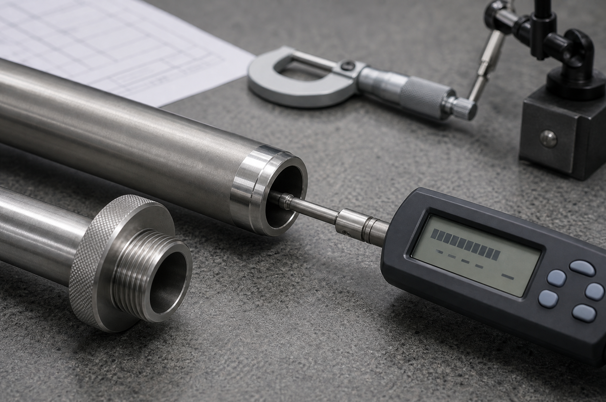
Inspection on a connecting tube is unusual because two suppliers have to contribute to it: the mill for the body, the machine shop for the ends. A report that does not separate the two is not traceable.
| Check | Method | What it establishes |
|---|---|---|
| Tube OD and wall | Mill certificate values, verified by micrometer and wall gauge on the lot | The body's actual dimensions, as opposed to the nominal the drawing assumed |
| Grip-zone OD | Micrometer at several positions around the circumference, or a three-point gauge | Whether the diameter the clamp sees is round as well as on size |
| Bore diameter and roundness | Bore gauge or internal micrometer, two axes at 90°, at two depths | Whether the bore is a cylinder or a taper with an oval entry |
| Thread | Plug or ring gauge to the specified standard, plus visual on crest condition | Whether the thread will assemble; not whether it will seal |
| Overall length | Height gauge or caliper, after deburr | The axial dimension the assembly actually uses |
| Runout between ends | Between centers or on V-blocks with a dial indicator | Whether the two functional ends share an axis |
| Surface roughness on the seal band | Portable roughness tester, or comparison against a sample | The finish a seal or ferrule has to travel over |
| Material identity | Mill certificate, and PMI where the project specifies it | That the grade supplied is the grade specified |
| Passivation evidence | Process record per batch; a water-break or copper-sulphate test where required | That the treatment was performed and recorded, not that the part is corrosion-proof |
| Leak or proof test | Only when specified: defined assembly, medium, pressure, hold time and acceptance criterion | The performance of that assembly under that test — and nothing wider |
The last row is the one that decides whether a project can be quoted honestly. A dimensional inspection passing does not mean the part is pressure-tight, because containment is a property of the assembled joint: the tube, the clamping element, the torque or travel applied to it, the mating port and the medium. A tube that holds at one assembly torque and leaks at another has not changed; the assembly has.
| Document | Who issues it | What it covers |
|---|---|---|
| Mill certificate, EN 10204 3.1 or 2.2 | The tube mill, through the distributor | Heat number, chemical composition, mechanical properties, and the standard the tube was made to |
| Dimensional inspection report | Us, per drawing and sampling plan | The machined features: lengths, diameters, threads, runout, finish |
| First article inspection report | Us, on the first part of a new drawing or revision | Every dimension on the drawing, with the method used, so the drawing is proven before a run |
| Material test certificate for bar or forgings | The material supplier | Only relevant where the ends are machined from bar or a forged collar rather than from tube |
| Passivation and cleaning record | Us, per batch | Bath, cycle and date; the traceable evidence that the treatment happened |
| Leak or proof test report | Us or a nominated laboratory, when specified | The test as run: assembly, medium, pressure, duration, result |
The Joint Is Finished at Assembly, Not at the Machine
Three of the parts in a clamp joint are made elsewhere, and the operation that closes them is performed by your assembler or by ours. That makes the assembly procedure part of the product definition, in a way that is unusual for a machined component. Two identical tubes, made to the same drawing, can produce one leak-free joint and one weeping joint depending on what happens at the nut.
1Torque or turns, not feel
A ferrule set is closed by a specified number of turns past finger-tight, or by a torque figure, and the two are not interchangeable across sizes. Under-tightening leaves the ferrule short of its grip; over-tightening plastically deforms the tube and destroys the section that was measured. Either way the part is condemned for a reason that does not appear on the inspection sheet.
2Insertion depth has to be visible
The tube must seat fully into the body before the nut is tightened. A tube that stops 2 mm short still tightens, still gauges, and leaves the ferrule gripping the wrong band. This is why a depth mark scribed at the shop, or a shoulder that bottoms, is worth more than a note on the drawing.
3Ferrules are single-use
A ferrule that has been closed once has taken a set and will not seal a second time on a different tube. Re-making a joint with the same ferrule is one of the most common causes of a leak that appears only after maintenance — and it is invisible in a parts list, because the part is still there.
4Clean before close, both ends
Machining debris in the bore reaches the seat, the instrument and the process. A bore that is clean at the shop can be contaminated by the deburr of the other end. Blowing through, capping, and a final visual on the bore belong in the packing operation, not in a hope.
Where a customer assembles in-house, the useful deliverable is not only the part: it is the insertion depth, the closing specification, the ferrule part number that was assumed, and a note on which end is which if the two differ. That sheet is cheap to produce at quotation and expensive to reconstruct after a leak.
Where These Tubes Are Used
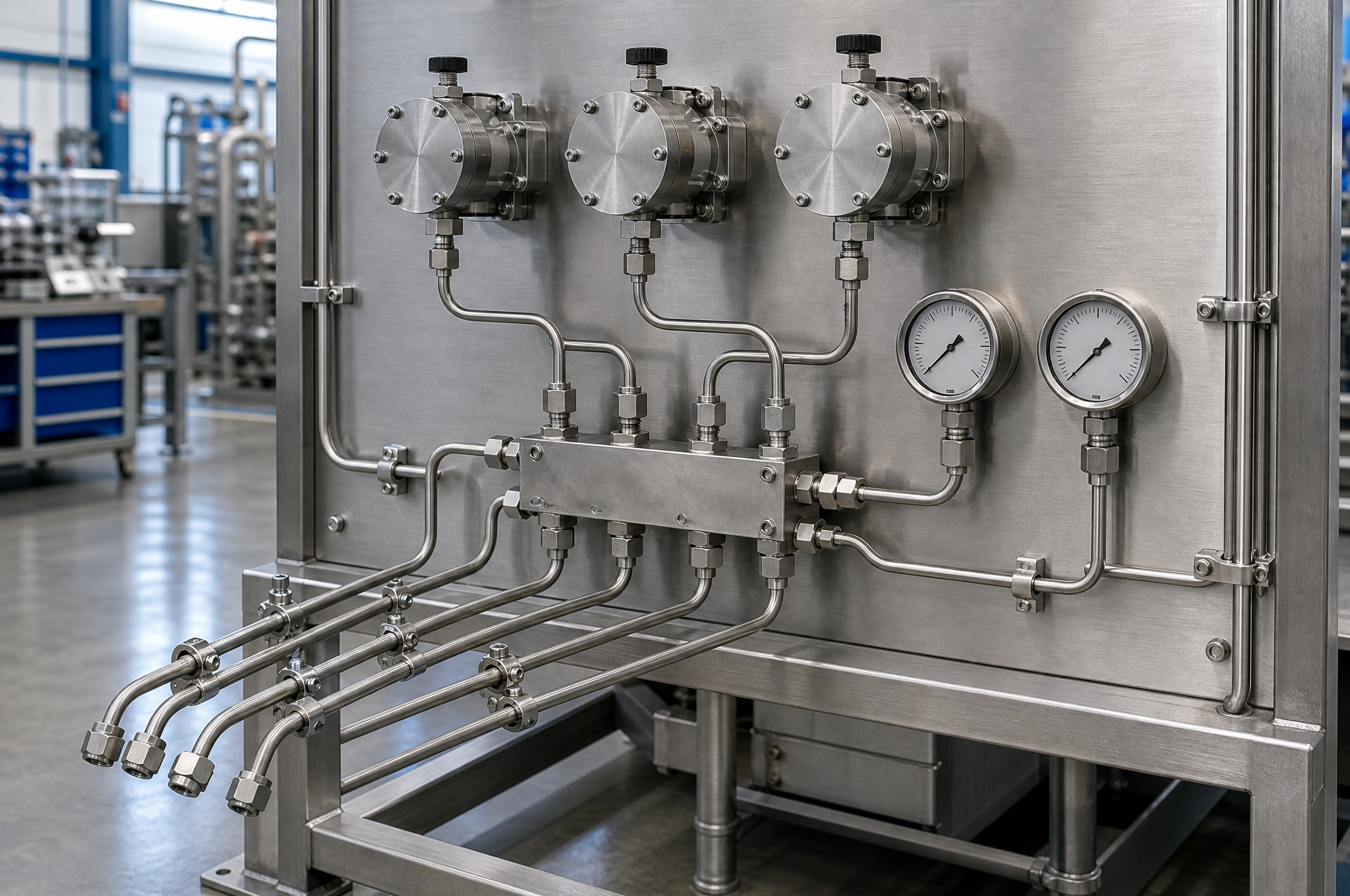
Fluid panels and skids
Bent tube runs between pumps, valves, filters and instruments on a common frame. The engineering problem is cumulative position error: each port is placed to its own tolerance, and the tube between two of them has to absorb the sum.
Watch for: bend position tolerance, end angle, and whether the run is measured in free state or installed.
Instrumentation and analyzer systems
Small-bore tube where the bore volume matters, dead volume at the joint matters, and the medium may be a sample rather than a process fluid. Cleanliness of the bore is a functional requirement here, not an aesthetic one.
Watch for: bore finish, dead volume at the ferrule, and purgeability.
Food, beverage and pharmaceutical equipment
Product-contact tube in a machine that is cleaned in place. The requirement is a drainable bore, a joint with no crevice to trap product, and a finish that the cleaning chemistry can reach and the verification method can prove.
Watch for: 316L with certificate, Ra target, weld quality and post-weld treatment.
Heat transfer and cooling circuits
Tubes carrying coolant or a thermal medium between a manifold and a cold plate, often in a tight envelope with several bends. Wall thickness is set by pressure and by how much the bend thins the outside of the radius.
Watch for: wall at the bend, bend radius against OD, and vibration support.
Semiconductor and high-purity gas
Where the requirement escalates from “clean” to a documented surface and a documented cleaning process, with the tube supplied to a purity specification rather than a general one.
Watch for: whether the specification is actually achievable on the tube stock before it is quoted.
Marine and offshore equipment
316L is the usual choice and it is not invincible: stagnant chloride-bearing fluid in a tube that drains poorly is a pitting environment regardless of grade, and a crevice at a support is where it starts.
Watch for: drainage, support detailing, and whether the medium is stagnant.
These are application descriptions, not customer references. Project names, drawings and test data from other customers are not published without written permission.
What the Drawing Has to Carry
A connecting tube is one of the few parts where an incomplete drawing produces a part that is correct and useless. The ten fields below are the ones that decide whether the quote, the machining and the inspection are all about the same object.
| Field | What to state | What goes wrong if it is missing |
|---|---|---|
| Material and tube specification | Grade plus the tube standard and tolerance class: 316L to ASTM A269, for example | Quoted on a cheaper tube with wider OD and wall, which moves the joint |
| Tube OD and wall | Nominal with the tolerance, and the minimum wall allowed after machining | The end is machined until the wall is thinner than the design pressure needs |
| Overall length | Between which faces, measured before or after finishing | Length differs by the finishing allowance, and the run does not close |
| End A and End B geometry | A dimensioned detail of each end, separately — the two need not match | The shop assumes a symmetrical part and the second end is guessed |
| Thread specification | Standard, size, pitch, class, and whether it is a sealing or a clamping thread | A parallel thread is treated as self-sealing, or the wrong standard is cut |
| Sealing feature | Face, groove or cone; its dimensions; the finish band on it | The seal has a dimension but no surface, and a chattered band passes inspection |
| Datum and runout | The tube OD over a stated length, and the runout at the far end relative to it | Each end is checked against itself and the pair is never checked at all |
| Tolerance allocation | General tolerance, plus the specific features that carry a tighter one | One blanket figure is applied to features that cannot possibly hold it |
| Surface and finishing | As-machined, passivated, pickled, electropolished or polished, with the Ra target where relevant | Electropolishing is added after the bore is finished to size, and the bore comes back oversize |
| Inspection and test scope | Which dimensions, which report, whether a leak or proof test applies and to what | “100% inspection” is quoted, and nobody agrees on what was inspected for |
Five drawing habits that cost money
- One tolerance for everything. A ±0.005 mm block tolerance applied to a 300 mm thin-wall tube is not a demanding drawing, it is an unquotable one. Allocate: general, then the two or three features that actually function.
- A thread with no wall behind it. Check the remaining wall under the thread root against the pressure and the corrosion allowance. If the number is uncomfortable, the design needs a thicker section, not a better machinist.
- A bend and a machined end with no relationship. If the end is machined after bending, the end is referenced to the bend, and the bend's position tolerance becomes the end's. State which feature is the datum after forming.
- Concentricity without a datum. “Concentric to 0.02” between two features does not say which is the reference. Write the datum, then the runout.
- A finish callout with no process. “Ra 0.4” can be reached by polishing, by electropolishing or by a different tube, and each has a different effect on the bore size and the edge condition.
Machined Connecting Tube, Catalog Fitting, or Welded Spool
There are three normal ways to join two ports, and the honest answer is that two of them are usually better than custom machining. This comparison exists so that the enquiry lands in the right place.
| Criterion | Machined connecting tube | Catalog fitting and tube | Welded pipe spool |
|---|---|---|---|
| Non-standard length or end geometry | The reason this route exists: any length, any two ends, one part | Limited to combinations the catalog supports | Possible, but each joint is a weld to qualify and inspect |
| Wall and bore matched to a flow requirement | Bore can be sized and finished to the drawing | Bore follows the tube and the fitting bore, with a step at each joint | Bore follows the pipe schedule |
| Leak paths | Two joints, both at the ends | Two or more joints, all mechanical | Welds: no elastomer, but each weld is a inspection item |
| Assembly time at your line | One part replaces a fitting stack | Highest — each element is fitted and tightened | Low at assembly, high at fabrication |
| Prototype and low volume | Economic: no tooling, and the drawing is the only cost | Economic if the catalog has the combination | Poor: welding procedure and inspection dominate |
| High volume, standard sizes | The expensive option | The right answer, on price and availability | Competitive at large diameter |
| Change control | A revision to one drawing | Whatever the catalog offers | A re-qualified weld procedure if the joint changes |
| Traceability | Mill certificate plus a dimensional report on the machined ends | Catalog certificates, per element | Weld records, filler certificates, NDT reports |
What Moves the Price
These tubes are quoted per part, but the price is driven by a small number of process decisions. Knowing which ones your drawing controls is the difference between a quote you can act on and one you have to re-cut.
| Driver | Why it costs | Where there is room to trade |
|---|---|---|
| Wall thickness relative to OD | Thin sections need collets, supports, lighter cuts and more passes; the same part in a thicker wall runs several times faster | Increase the wall where the design allows, especially at a threaded end |
| Number of machined ends | Two ends means a second setting, a second datum and a second inspection | Accept a welded or brazed end where one end does not need to be machined |
| Thread length and form | Threading a thin wall is slow, and the gauge check is per part | Shorter effective thread, or a standard form instead of a special |
| Tolerance class | Each tightened feature adds a process step and an inspection gate | Tighten only the features in the tolerance chain of the joint |
| Runout between ends | A total runout may force between-centers work or a plug support | Ask whether the assembly needs it, or only one end does |
| Finishing | Passivation is a batch operation and cheap per part; electropolishing is a separate cycle with a dimensional allowance | Electropolish the bore only, where the requirement is product contact |
| Inspection scope | Per-part gauging of a thread or a bore is labour, not machine time | Move to a sampling plan with a documented first article |
| Tube specification | A269 against A554, or a 3.1 certificate against 2.2, changes material cost before any machining | Buy the specification the joint needs, not the best available |
| Quantity and repeatability | Setup is amortised over the run; a repeat order with the same drawing is much cheaper than a first order | Order the annual quantity in call-offs against one setup |
Frequently Asked Questions
Can you machine stainless steel connecting tubes to our drawing?
What is the difference between a connecting tube and a pipe connector?
Which stainless grade should we specify for a connecting tube?
What tolerance can you hold on a machined tube end?
Does the tube come with a pressure rating?
Can you cut a thread directly on a thin-wall tube?
What is the difference between NPT, BSPP and BSPT for a tube end?
Can an electropolished bore be supplied?
How do you stop a thin tube from going oval when it is machined?
Can you supply a material certificate with the tubes?
Can you make a connecting tube from a sample if we have no drawing?
Is 316L suitable for seawater and for food contact?
What information do you need to quote a custom connecting tube?
Send the Drawing, the Tube Specification and the Joint
The review that decides the price happens before the tube is cut. Send the dimensioned 2D drawing with both ends detailed, the tube standard and tolerance class, the clamping or sealing element you intend to use, the medium and the operating conditions, and the inspection or test scope your quality plan requires. You get a response on the tube specification, the end geometry, the tolerances each feature can hold, and the finishing route.
Request a Tube QuoteSTEP, IGES, DWG, DXF or PDF drawings · prototype through repeat production
Related Capability Pages
Material grades, stock forms and equivalent specifications are set out in the materials guide; turning, milling and inspection capability sits under CNC machining services; the quality management system and the certificates we hold are on the quality certifications page.