
Design for Additive Manufacturing (DfAM): An Engineering Guide
Design parts for the printing process — not simply for CAD. This guide covers build orientation, wall thickness, overhangs, supports, tolerances, materials, anisotropy, post-processing and cost across polymer and metal additive manufacturing — and shows where conventional manufacturing is still the better answer.
STEP · STL · IGES · 3MF · OBJ · SolidWorks · CATIA accepted. Drawings and models are treated as confidential; NDA available on request before file transfer.
Key Takeaways
- DfAM is process-specific design, not printability checking. A model that slices cleanly can still fail in service if load paths run across layer interfaces.
- Build orientation is the highest-leverage decision in the whole review. It governs strength, accuracy, surface finish, support volume, build time and unit cost at the same time.
- There is no universal DfAM rulebook. FDM, SLA, SLS, MJF and metal powder bed fusion impose genuinely different limits on walls, overhangs and tolerances.
- Most of the cost is locked in before the machine starts. Build height, material volume, support strategy and post-processing scope are decided in CAD.
- Anisotropy is real. Layer-based parts are generally weaker across layers than within them; orientation and test coupons are how you manage it.
- Additive wins on complexity and iteration, not on unit cost. High volume and simple geometry usually still belong to injection moulding or CNC machining.
- Critical interfaces usually still need machining. The strongest DfAM results come from designing the printed near-net shape around the features that will be cut.
What Is Design for Additive Manufacturing (DfAM)?
DfAM is not a synonym for "3D printing design tips". It is a design discipline with a specific definition, a maturity ladder and a set of trade-offs that are different from every conventional process.
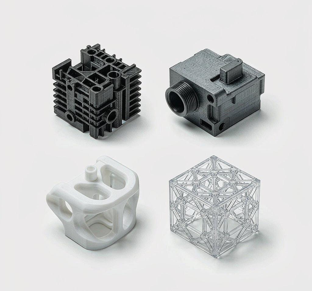
Short answer
Design for Additive Manufacturing (DfAM) is the practice of designing or redesigning a component around the capabilities and constraints of a specific additive manufacturing process — build orientation, layer behaviour, support strategy, material anisotropy and post-processing — instead of adapting an existing model until it happens to print.
That last clause matters. The most common failure we see is not a print failure at all: it is a part that prints perfectly and still underperforms, because the geometry was optimised for a cutting tool or a mould and then sent to a layer-based process unchanged. The result is a component that carries the cost structure of additive manufacturing without gaining any of its advantages.
DfAM therefore has a different objective from conventional DFM. The goal is not simply manufacturability — it is the balance of four outcomes at once: performance, manufacturability, cost and lead time. A design that prints easily but needs four hours of hand finishing has not achieved DfAM; it has moved the cost to a different line.
Three levels of AM adoption
Most organisations move through three stages. Knowing which stage a project is in tells you how much of the benefit is actually on the table.
Direct conversion
An existing part — usually a machined or moulded design — is printed as-is. Fast to quote, easy to approve, and almost always a poor use of the process.
Outcome: printability, not performanceModified for AM (MfAM)
The geometry is adapted: walls thinned, ribs added, supports reduced, a few features merged. This is where most good production parts sit.
Outcome: real gains, moderate redesign effortTrue DfAM
The part is conceived from the load case and the process upward — topology optimisation, lattice structures, conformal channels, part consolidation. Requires validated load data and a qualification plan.
Outcome: performance not achievable conventionallyDirect conversion → MfAM → DfAM · effort and qualification burden increase left to right
Why DfAM cannot be a single rulebook
Because "additive manufacturing" is a family of processes with different physics. A wall thickness that is comfortable in SLS can be unprintable in FDM. An overhang that needs heavy support in metal powder bed fusion may be entirely self-supporting in SLS, where the surrounding powder bed holds the part. Any DfAM rule stated without naming the process is a rule of thumb, not a specification.
That is why the process-specific section of this guide exists, and why our engineering reviews always start by fixing the process and material before discussing geometry.
DfAM vs DFM: How the Design Philosophy Changes
Every manufacturing process rewards certain geometry and punishes other geometry. The table below is the fastest way to see why a design that is excellent for machining or moulding is often mediocre in additive — and vice versa.
| Design factor | CNC machining | Injection moulding | DfAM (additive) |
|---|---|---|---|
| Geometry strategy | Simplify for tool access | Simplify for mould release | Complexity can create value |
| Draft angle | Usually not required | Usually required | Process-dependent |
| Undercuts | Increase machining complexity | Increase tooling complexity | Often feasible |
| Internal channels | Difficult, often drilled and plugged | Usually require side cores | Often highly feasible |
| Part consolidation | Limited | Limited | Strong opportunity |
| Wall thickness driver | Tool reach and rigidity | Mould flow and cooling | Process, material and thermal behaviour |
| Orientation | Secondary | Secondary | Critical |
| Support | None (fixturing instead) | None | Process-dependent |
| Anisotropy | Generally lower | Usually lower | Important for many processes |
| Cost driver | Material + machining time | Tooling + cycle time | Material + build time + supports + finishing |
| Economical volume | Low to medium | High | Low to medium |
Complexity stops being a cost
In machining and moulding, every added feature costs tool time or tooling steel. In additive, a more complex outer skin often costs nothing extra — as long as you do not add material volume, height or supports.
Orientation replaces tooling
Where a mould imposes a parting line and a cutter imposes tool reach, additive imposes a build direction. It is the decision that substitutes for tooling — and you make it on every single part.
Freedom is not free
"AM can make any shape" is true for geometry and false for economics. Unsupported spans, trapped powder, enclosed voids, tall builds and cosmetic requirements all convert geometric freedom back into cost.
Related reading: CNC Machining and Additive Manufacturing — how the two processes are combined on one part.
When Is DfAM the Right Design Approach?
A credible DfAM guide has to be able to say "not this time". These are the signals we look for — in both directions — before recommending additive over conventional manufacturing.
Signals that favour DfAM
Each one compounds with the others. Two or more usually justify a serious DfAM review.
- Complex internal geometry — conformal cooling, flow paths, lattice, hidden voids
- Genuine part consolidation opportunity with a real assembly cost behind it
- Weight reduction is a functional requirement, not a preference
- Low-to-medium volume where tooling cannot be amortised
- Short design iteration cycles and frequent geometry changes
- Lead time matters more than unit price
- Customised or patient/operator-specific geometry at low batch size
→ DfAM is likely to create measurable advantage.
Signals that favour conventional manufacturing
These are not objections to additive — they are cases where another process simply wins.
- Very high production volume with a stable design
- Simple prismatic geometry with no internal features
- Commodity material where bar or plate stock is cheap
- Aggressive unit-cost target that dominates the business case
- Tight tolerances or bearing fits across many features
- Cosmetic Class-A surfaces required straight from the process
- Qualification pathway that assumes wrought or moulded material properties
→ Machining, moulding, die casting or sheet metal is likely the better route.
The DfAM Workflow: From CAD to Production
This is the design-decision sequence an engineer runs before a part is released. It is deliberately different from a production order workflow — the questions here are answered in CAD, not on the machine.
Design requirements
Load cases, environment, life, regulatory constraints, inspection plan.
Process selection
FDM, SLA, SLS, MJF or metal PBF — chosen before geometry is frozen.
Material selection
Based on service temperature, chemical exposure, mechanical load and certification needs.
Geometry review
Walls, ribs, holes, channels, fillets, draft-free features, minimum feature size.
Orientation optimisation
Strength, surface, accuracy, support volume and build height balanced together.
Support strategy
Where supports are unavoidable, how they will be removed, and what marks are acceptable.
Tolerance definition
Functional dimensions identified; everything else left at general tolerance.
Post-processing plan
Support removal, cleaning, curing, finishing, machining allowance, coating.
Prototype / test coupon
Built in the production orientation, with the production parameters.
Inspection & validation
Dimensional report, functional test, mechanical test where required.
Production release
Frozen orientation, parameters and inspection plan documented for repeat builds.
Change control
Any geometry change re-runs steps 4–10. Orientation is part of the drawing.
The step teams skip most often
Step 10 — inspection and validation — and step 12 — change control. A part validated in one orientation is not validated in another. If orientation is not recorded on the release documentation, the next build is a different part, regardless of how identical the STL file is.
12 Essential DfAM Design Rules
These are the rules we apply in engineering reviews. Each one is stated as a rule → why it matters → what to do, and each is qualified by process wherever the answer is process-dependent.
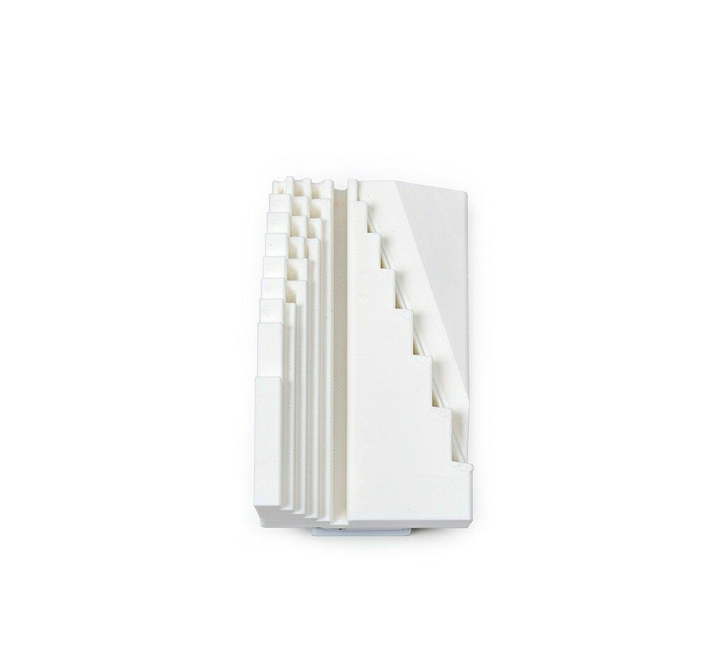
Select the AM process before finalising geometry
Process choice sets every downstream limit: minimum wall, minimum feature, achievable tolerance, support behaviour, thermal distortion and surface finish. Changing process after the geometry is frozen means a redesign, not a parameter tweak.
Do this: name the process on the drawing or model notes, alongside the material and the agreed build orientation.
Design around build orientation
Orientation determines which surfaces need support, how layer interfaces sit relative to service loads, where stair-stepping appears, how tall the build is, and therefore how long and how expensive it is.
Do this: orient so critical load paths run within layers, critical surfaces avoid support contact, and build height is minimised — then record that orientation as part of the released data.
Control wall thickness
Walls that are too thin fail during build, cleaning or handling. Walls that are unnecessarily thick add material cost, build time, residual stress and warpage risk. Uniform thickness is not automatically correct — it is simply the default that CAD produces.
| Process | Typical starting range |
|---|---|
| FDM | approx. 1.0–1.5 mm |
| SLA | approx. 0.5–1.0 mm |
| SLS | approx. 0.7–1.0 mm |
| MJF | approx. 0.7–1.0 mm |
| Metal PBF | process, material and geometry dependent |
Why we qualify this: the practical minimum depends on machine, material, nozzle or laser parameters, wall height, orientation and required mechanical performance. Treat these as conversation starters and confirm against a material datasheet and a test build.
Control overhangs and supports
Down-facing surfaces at a shallow angle to the build direction need support. Supports cost material, machine time and finishing labour, and they leave marks on the surfaces they touch.
The 45° rule: overhangs steeper than roughly 45° from horizontal are self-supporting on many processes. It is a starting heuristic, not a standard — the real limit depends on process, material, layer height, cooling and span length. Do this: replace horizontal holes with teardrop profiles, chamfer undersides, and split long spans.
Design for anisotropy
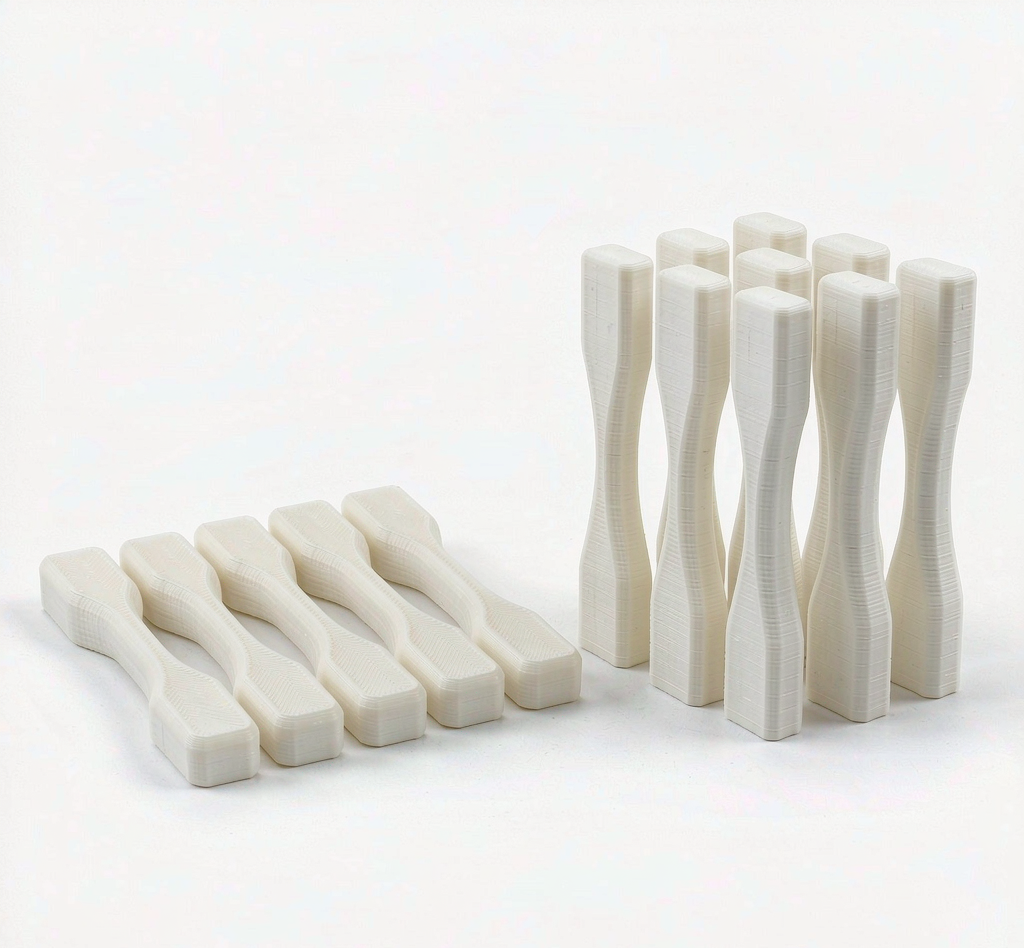
Layer-based parts are generally weaker across layers than within a layer. Tensile strength, elongation, fatigue life and impact resistance all depend on how the part sits relative to its service loads.
Do this: identify the primary load path first, then orient so that path lies within the layer plane wherever possible. Validate with test coupons built in the same orientation — never with coupon data from a different build direction.
Define tolerance at the functional level only
Over-specifying tolerance is one of the most expensive habits in manufacturing. A dimension that carries no function does not need a tight tolerance, but every tight tolerance drives process selection, inspection time and scrap.
Do this: mark functional dimensions and fits explicitly, leave everything else at a general tolerance, and hand anything genuinely tight to a secondary machining operation with a defined allowance.
Avoid unnecessary large flat sections
Large flat areas parallel to the build plate concentrate thermal stress, promote warpage and curl, need dense support, and make the part prone to detaching from the plate or cracking between layers.
Do this: break up large flats with ribs, gussets, slight curvature or coring. Ribs usually cost less material than the solid wall they replace and they reduce distortion at the same time.
Fillet stress-critical internal corners
Sharp internal corners concentrate stress and are also a crack initiation site in layer-based parts, because the layer interface near a corner is already a plane of weakness.
Do this: distinguish structural fillets (sized by load and fatigue analysis, verify them) from cosmetic fillets (sized by appearance and cleanability). Do not apply a blanket fillet — it hides the features that actually matter.
Design holes and internal channels for the process
Internal geometry is additive's biggest advantage and its most common failure point. Unremoved powder, trapped resin and inaccessible cavities cause failures long after the print itself succeeded.
Do this: give every internal void at least two openings, size them for the cleaning method, avoid dead ends and sharp turns, and prefer self-supporting cross-sections. Verify evacuation with a test build before production.
Design for post-processing from the start
Post-processing is not a downstream detail. Support access, drainage, fixturing for machining, coating coverage and inspection reach are all determined by geometry — and they are frequently the largest labour component of an AM part.
Do this: decide the finishing route before release, then design access for it. If a face will be machined, add the allowance and a datum feature. If a channel will be flushed, design the ports.
Consolidate parts only where it adds value
Part consolidation eliminates fasteners, seals, assembly labour and leak paths. It is the most cited DfAM benefit — and the most over-applied. A consolidated part is also a single point of failure with harder inspection and no field repair.
Do this: consolidate where assembly cost, sealing or alignment is the real problem. Keep separate parts where serviceability, inspection access or failure isolation matters more.
Validate before production
Additive parts are sensitive to parameters that a drawing does not capture: orientation, support layout, machine, material batch and post-processing route. A design validated once in one configuration is not validated in another.
Do this: build test coupons with the production job, inspect critical dimensions, run the functional test, and freeze orientation and parameters in the release documentation.
DfAM Guidelines by Additive Manufacturing Process
General rules get you to a printable part. Process-specific rules get you to a production part. These are the constraints that change most between processes.
| Parameter | FDM | SLA | SLS | MJF | Metal PBF |
|---|---|---|---|---|---|
| Min. wall thickness | Process dependent | Process dependent | Process dependent | Process dependent | Process dependent |
| Overhang behaviour | Support dependent | Support dependent | Geometry dependent | Geometry dependent | Support dependent |
| Orientation importance | High | High | Medium–high | Medium–high | Very high |
| Anisotropy | High | Material dependent | Lower | Lower | Important |
| Support requirement | Often | Often | Usually none | Usually none | Often, plus heat dissipation |
| Powder / resin evacuation | N/A | Important for hollow parts | Important | Important | Important |
| Dominant risk | Warpage, delamination | Trapped resin, cure shrinkage | Powder trapping, thermal growth | Dimensional consistency across the bed | Residual stress, distortion |
| Post-processing load | Moderate | Moderate | Cleaning | Cleaning | Significant |
FDM Fused Deposition Modelling / FFF
Material is extruded as a bead and welded to the layer below. Strength across layers is the weakest axis, and the thermal history of the part drives distortion.
- Walls: relate minimum wall to nozzle diameter and bead count, not to a single global number
- Orientation: keep primary load paths in the layer plane; avoid loading across bead interfaces
- Bridging: short spans are feasible; long horizontal spans sag and need support
- Warping: large flat bases and sharp corners curl — add radii, ribs or a brim strategy
- Holes: horizontal round holes usually need support or a teardrop profile
- Infill: set it by load requirement, not by default — sparse infill under a loaded face is a common failure
- Heat: check service temperature against the material's heat deflection behaviour
- Anisotropy: the most pronounced of the polymer processes; validate in the production orientation
SLA Stereolithography / resin
A laser cures liquid resin layer by layer. Fine feature resolution and smooth surfaces are the strengths; trapped resin and cure shrinkage are the risks.
- Thin walls: feasible, but long unsupported thin sections flex during peel and can tear
- Trapped resin: hollow parts must have drain holes; uncured resin left inside will crack the part later
- Drain holes: at least two, positioned so the cavity drains fully in the wash orientation
- Support marks: plan support placement away from cosmetic and sealing faces
- Orientation: drives both surface quality and cross-sectional peel forces
- Curing: post-cure changes dimensions and brittleness — validate after curing, not before
- Large flats: suction forces during peel can fail the part or the film
- Tolerances: among the best as-printed, but still sensitive to orientation and support
SLS Selective Laser Sintering (powder bed)
Unsintered powder supports the part, so most geometry is self-supporting and supports are rarely needed. That freedom shifts the risk to powder removal and thermal control.
- Powder removal: the dominant constraint — design openings, avoid blind cavities
- Wall thickness: thin sections can over-sinter or distort; very thick sections accumulate heat
- Clearance: moving or assembled features need clearance for unsintered powder and surface roughness
- Packing density: nesting affects both cost and dimensional consistency across the build
- Warpage: large flat parts are the highest-risk geometry in the powder bed
- Orientation: less critical for support, still critical for surface and accuracy
- Surface: naturally matte and slightly porous — plan sealing if the part must hold pressure
- Threads: usually machined or inserted rather than printed directly
MJF Multi Jet Fusion
A fusing agent is jetted onto a powder bed and fused with infrared energy. Like SLS, the powder bed supports the geometry; the differentiators are feature resolution and consistency across the build volume.
- Feature size: fine details and small text are limited by agent deposition and powder
- Packing: dense nesting improves unit economics but affects thermal consistency
- Orientation: affects surface finish, mechanical properties and achievable accuracy
- Cooling: controlled cooling drives dimensional stability — thick and thin sections in one part cool at different rates
- Dimensional consistency: verify across the build volume if parts are used interchangeably
- Powder evacuation: same discipline as SLS — no blind cavities
- Wall transitions: avoid abrupt thick-to-thin jumps where possible
- Production use: well suited to repeat low-to-medium volume runs once parameters are frozen
Metal powder bed fusion (LPBF / DMLS / SLM)
A laser melts metal powder layer by layer. The design constraints are dominated by thermal behaviour: residual stress, distortion, and the need for supports that also act as heat sinks.
- Supports: required for overhangs and for heat conduction — not optional decoration
- Overhang: shallow down-facing angles produce dross and poor surface quality
- Thermal stress: large cross-sections and abrupt thickness changes drive distortion and cracking
- Anisotropy: properties vary with orientation and are further changed by heat treatment
- Powder evacuation: internal channels need generous, well-placed openings
- Heat treatment: stress relief or HIP changes both properties and dimensions — machine after, not before
- Machining allowance: always add stock on mating faces, bores, threads and sealing surfaces
- Qualification: plan inspection, mechanical testing and documentation before the first build
Material Selection in DfAM
Material choice is not a dropdown at the end of the design. It interacts with process, orientation, wall thickness and post-processing, and it is usually constrained by service environment long before it is constrained by printability.
| Material family | Typical processes | Design consideration that usually governs |
|---|---|---|
| Nylon PA12 / PA11 | SLS, MJF | Toughness, chemical resistance, moisture absorption and dimensional drift |
| Glass-filled nylon | SLS, MJF | Stiffness and heat resistance, at the cost of surface finish and abrasive wear on mating parts |
| TPU / elastomers | SLS, FDM | Flexibility makes support removal and powder evacuation harder; avoid deep narrow channels |
| Standard & tough resins | SLA | Brittleness after post-cure; snap-fits and thin living hinges need generous radii |
| High-temperature resins | SLA | Heat deflection and stiffness retention; usually a secondary-cure requirement |
| ABS / ASA / PC | FDM | Warpage control, enclosure temperature and interlayer bond strength |
| Aluminium AlSi10Mg | Metal PBF | Lightweighting and thermal conductivity; supports and stress relief are mandatory |
| Stainless steel 316L / 17-4PH | Metal PBF | Corrosion resistance and strength; heat treatment route changes final properties |
| Titanium Ti6Al4V | Metal PBF | Strength-to-weight and biocompatibility; high residual stress and strict qualification |
| Maraging / tool steels | Metal PBF | Tooling and high-strength applications; dimensional change through ageing must be allowed for |
Environment first, printability second
Service temperature, chemical exposure, UV, flame and smoke requirements, food or medical contact, and the mechanical load case eliminate most candidates before printability is even considered. A material that prints beautifully and fails in the field is the most expensive kind of material.
Ask for the datasheet, not the brand name
AM material properties are machine- and parameter-specific. For any load-bearing or regulated part, request the material certificate and the property data generated on the actual machine and parameter set that will be used.
Material data for the processes we run, including standard grades and available grades, is listed in the Materials section.
Build Orientation and Anisotropy
If a DfAM review can only change one thing, change the orientation. It is the decision that simultaneously governs strength, accuracy, surface finish, support volume, build time and cost.
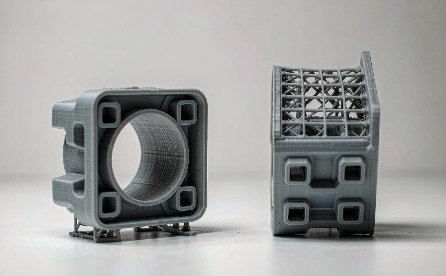
What orientation actually changes
Layer vs load direction
Layer interfaces are the weak plane. Orienting so service loads run within layers is usually the single biggest strength improvement available without changing geometry.
Where the tolerance lands
Dimensional behaviour differs between the build direction and the layer plane. Critical dimensions should be oriented into the axis where the process is most repeatable.
Stair-stepping placement
Curved and angled surfaces show stair-stepping. Orientation decides whether those steps land on a cosmetic face or on a hidden one.
Volume and access
Orientation determines how much support is generated and whether a tool can physically reach it for removal.
Height is time
In most layer processes, height drives build time more than volume does. Laying a tall part down can cut hours from the job.
All of the above
Orientation is where strength, quality and cost are traded against each other in one decision. It belongs on the released drawing.
Anisotropy in practice
Overhang and Support Strategy
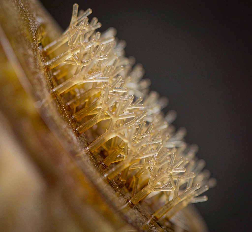
Supports are the tax additive manufacturing charges for geometric freedom. The goal is not to eliminate them — it is to place them where they are cheap to generate, reachable to remove, and absent from surfaces that matter.
Support reduction techniques that survive contact with reality
Make the feature self-supporting
- Teardrop or diamond holes instead of circular horizontal bores
- Chamfered undersides instead of flat down-facing skins
- Arches and domes instead of flat ceilings over a span
- Split long spans into stepped shorter ones
Put supports where they are cheap
- Keep supports off sealing faces, bearing seats and cosmetic surfaces
- Check that a tool can physically reach the support contact area
- Avoid supports inside channels or cavities that cannot be flushed
- Accept support marks on hidden faces to protect functional ones
Print failures are rarely caused by a single dramatic error — they accumulate from small oversights in orientation, support and thermal design. For a failure-mode view of the same problem, see Why Are 3D Prints Failing?
Tolerance, Accuracy and Surface Finish
Tolerance is where many AM projects lose their business case — not because the process cannot hit the number, but because the number was specified on a dimension that never needed it.
Specify tolerance functionally, not uniformly
A block tolerance applied to an entire model is the single most common source of unnecessary cost in additive manufacturing. Identify the dimensions that actually control assembly, motion, sealing or load transfer, tolerance those, and leave the rest at a general tolerance.
Non-critical geometry
Visual surfaces, clearances with generous gaps, ribs, bosses without mating parts. Leave these at general tolerance.
Functional interfaces
Bearing seats, sealing faces, threaded holes, precision bores, datum features. Add machining allowance and finish them on a machining centre.
Measured, not assumed
Whatever route is chosen, the critical dimensions go on the inspection plan and are reported. Assumed accuracy is not accuracy.
What governs as-printed accuracy
- Orientation — dimensional behaviour differs between the build axis and the layer plane
- Layer height — drives stair-stepping on curved and angled surfaces
- Shrinkage and thermal history — varies with section thickness, geometry and process
- Support strategy — contact points, removal damage and local distortion
- Post-processing — curing, heat treatment, blasting and coating all change dimensions
- Feature size — very small features lose definition before large ones do
Where machining takes over
When a feature genuinely needs a precision fit, the honest answer is usually to print it near-net and machine the interface. On Goldcattle's machining side, typical CNC tolerance is ±0.01 mm, with ±0.005 mm achievable on qualified features, and surface finish to Ra 0.4 μm where the operation and geometry support it. That is the route for bearing bores, sealing faces and threads — not the printer.
Surface finish expectations
As-printed surfaces carry layer texture whose direction and magnitude depend on orientation and process. Up-facing, down-facing and vertical walls finish differently on the same part. Common routes are bead blasting, tumbling, vapour smoothing, sanding, priming and painting — each with its own dimensional effect. Define the finish requirement by area of the part, not by a blanket "smooth finish" note, and confirm it on a sample before production.
Topology Optimisation, Lattice and Lightweighting
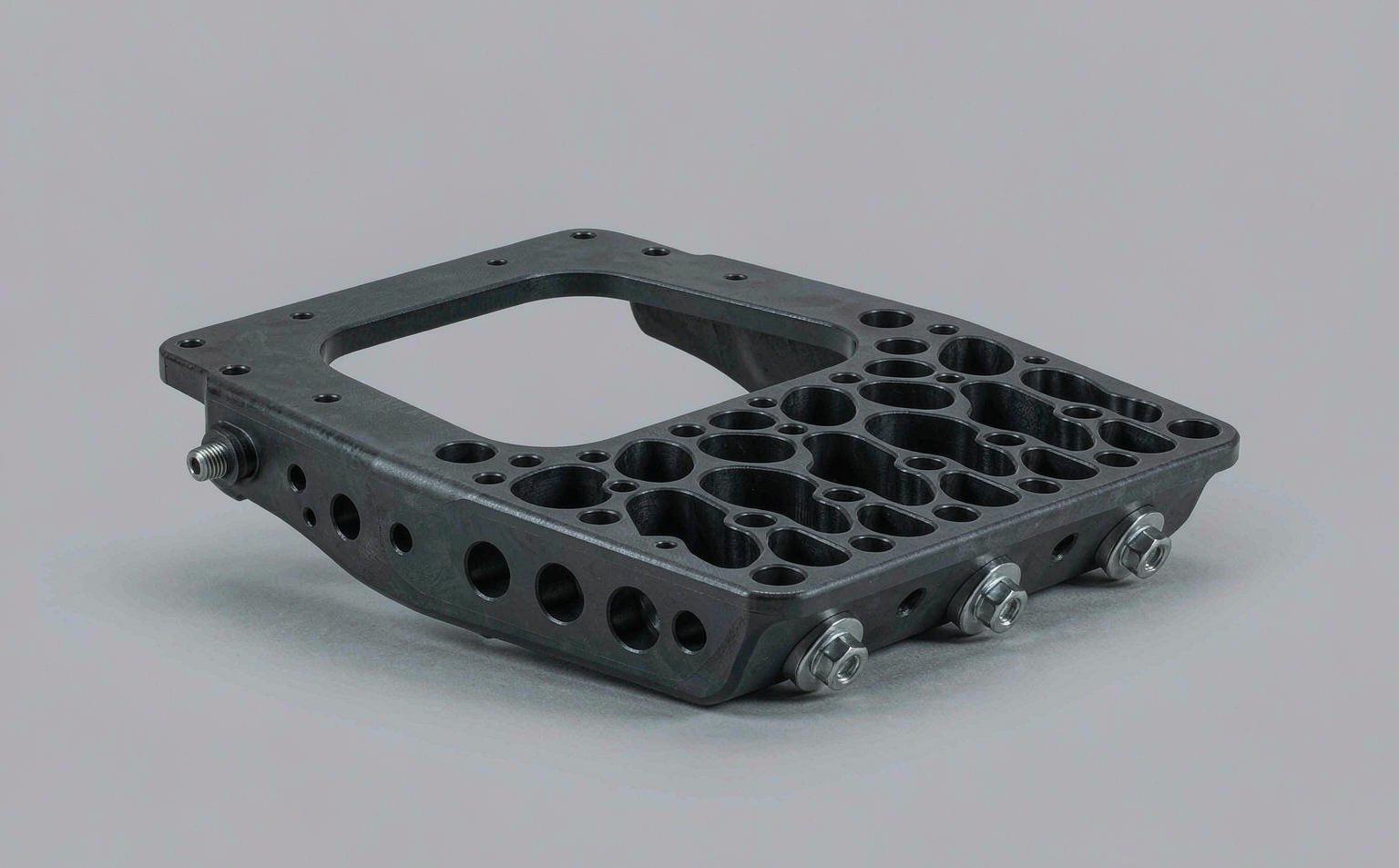
This is the level of DfAM that genuinely cannot be reproduced by machining or moulding — and the level that most often fails because it is treated as a geometry exercise rather than an engineering one.
Topology optimisation needs inputs, not just software
Topology optimisation removes material from a design space where it is not carrying load. The quality of the output is entirely determined by the quality of the inputs:
- Load cases — every real load case, including assembly, handling, transport and accidental load, not just the service load
- Design space — the volume the solver is allowed to remove material from
- Non-design space — interfaces, mounting faces and sealing surfaces that must survive untouched
- Constraints — stiffness targets, minimum feature size, symmetry, draw direction for any subsequent machining
- Manufacturing constraints — overhang limits, minimum member size, orientation
A topology-optimised result is a starting geometry, not a finished part. Raw solver output has organic surfaces, variable wall thickness and sharp transitions that suit neither the printer nor the inspector. The engineering work is in interpreting that result into manufacturable geometry and then validating it.
Lattice structures: when they pay and when they cost
Weight, stiffness-to-mass or energy absorption is the objective
Impact absorption, heat exchange, weight reduction in a stiff assembly, and medical or aerospace structures where the qualification pathway already exists.
Powder removal, inspection or fatigue governs
Trapped powder inside a closed lattice is a contamination and weight problem. Internal struts cannot be inspected easily, and fatigue life in a lattice is dominated by surface roughness and strut defects.
Practical advice: prefer open, self-draining lattice cells over closed ones; keep strut diameter above what the process can reliably fuse; and treat surface roughness on internal struts as a fatigue design input, not a cosmetic detail.
Part Consolidation: The Highest-Value, Most Over-Applied DfAM Move
Turning an assembly into a single printed component removes fasteners, seals, alignment steps and leak paths. It also removes serviceability, inspection access and failure isolation. Both sides of that trade belong on the table before the redesign starts.
Before you consolidate, answer these five questions
- What is the actual cost being removed? Fasteners, seals, alignment fixtures, assembly labour, inspection steps, warranty claims. If the answer is "nothing measurable", consolidation is a complexity transfer, not a saving.
- What happens when it fails? A consolidated part usually means replacing the whole component rather than one element. In service-critical applications that can be unacceptable.
- Can it still be inspected? Internal features that were visible as separate parts become inaccessible once merged.
- What is the build-failure exposure? If one consolidated part fails on the platform, you lose the whole assembly's worth of value, not one small component.
- Does the qualification pathway allow it? Regulated sectors may require validation data that is far easier to generate for a conventional assembly.
Post-Processing: Plan It as a Design Input
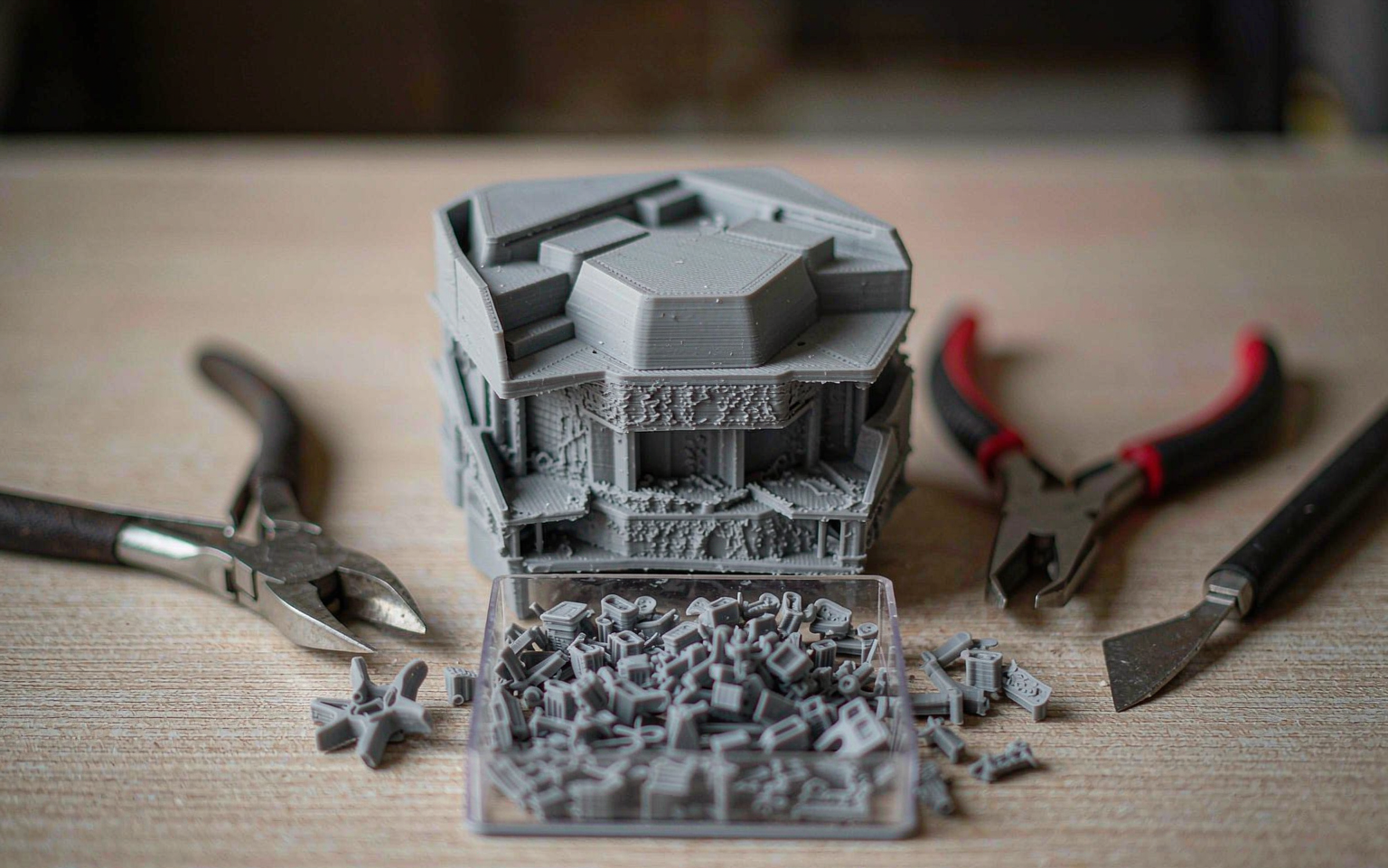
On many AM parts, post-processing is the largest labour component and the most common source of dimensional surprises. It is also the step most often left undefined until after quotation.
| Objective | Typical method | Design implication |
|---|---|---|
| Remove supports | Manual break-away, cutting, machining | Tool access to every contact point; accept marks on hidden faces |
| Remove powder / resin | Bead blasting, flushing, ultrasonic cleaning | Access ports sized for the method; no blind cavities |
| Complete cure | UV post-cure, thermal post-cure | Dimensions and brittleness change — validate after curing |
| Improve surface | Sanding, tumbling, vapour smoothing, blasting | Material is removed — allow stock on functional faces |
| Achieve fit | CNC milling or turning of critical features | Add machining allowance and datums to the printed geometry |
| Restore / set properties | Stress relief, HIP, ageing, annealing | Heat treatment moves dimensions — machine critical features afterwards |
| Protect or seal | Priming, painting, anodising, sealing, coating | Coating thickness affects fits; masking of non-coated areas |
| Add hardware | Threaded inserts, helicoils, bushings | Design boss geometry for the insert, not for a printed thread |
| Verify | Dimensional inspection, FAI, CT, mechanical testing | Define the inspection plan before the build, not after |
The rule that prevents most surprises
Every post-processing step changes the part. It removes material, adds material, or moves dimensions. A part validated before blasting, curing, heat treatment or coating is validated on the wrong part.
How DfAM Affects 3D Printing Cost
Additive manufacturing has no tooling to amortise, so almost all of the unit cost is decided in CAD. These are the six drivers that move a quote — and all six are design decisions, not purchasing decisions.
Build height
In layer-based processes, height usually drives machine time more than volume does. Flattening a part can cut hours from a build.
Material volume
Every cubic centimetre is material plus the time to deposit it. Coring and ribbing usually beat solid sections on both counts.
Support volume
Supports cost material, machine time, removal labour and surface repair. They are frequently the largest avoidable cost on a part.
Orientation
Orientation sets height, support volume, surface quality and scrap risk at the same time. It is a cost decision as much as an engineering one.
Part consolidation
A consolidated part is usually more expensive to print than any single piece it replaces — the saving comes from removing fasteners, seals and assembly labour.
Post-processing
Each added finishing step is labour. Specifying finish by area, only where it is functional, is often the single fastest way to reduce a quote.
Six changes that typically reduce an AM quote
- Reduce build height by re-orienting or splitting the part
- Core out thick sections and replace them with ribs
- Replace flat down-facing skins with chamfers or self-supporting profiles
- Limit tight tolerances and cosmetic finishes to the faces that need them
- Reduce the number of separate finishing operations by grouping requirements
- Increase batch quantity where possible — set-up and nesting efficiency spread across more parts
For a process-by-process view of our additive capability and typical lead times, see 3D Printing Services.
10 Common DfAM Mistakes
Ranked roughly by how often we see them in incoming designs. Most are cheap to fix in CAD and expensive to discover after the build.
1 · Designing for CNC and printing it unchanged
Inherits thick uniform walls and tool-access geometry, and throws away every advantage additive offers.
2 · Ignoring build orientation
Leaves strength, accuracy, surface finish and cost to chance — and makes the part impossible to validate repeatably.
3 · Uniform wall thickness everywhere
Creates either thin sections that fail in build or thick sections that warp and waste material.
4 · Generating unnecessary supports
Flat undersides and horizontal holes where a chamfer or teardrop profile would have been self-supporting.
5 · Forgetting powder or resin evacuation
Blind cavities and long narrow channels that cannot be cleaned — discovered weeks later as cracking or contamination.
6 · Specifying unrealistic tolerances
Block tolerances applied to the whole model, driving up cost and scrap on dimensions that carry no function.
7 · Ignoring anisotropy
Assuming isotropic datasheet values and orienting the part so service loads cross layer interfaces.
8 · Choosing material after geometry is frozen
Material drives wall thickness, minimum feature size and post-processing — it cannot be an afterthought.
9 · Leaving post-processing undefined
Finishing is quoted late, changes the dimensions, and invalidates the validation carried out before it.
10 · Optimising geometry without designing for inspection
A beautiful lightweight structure nobody can measure, and therefore nobody can release.
DfAM Release Reference
Read this as a set of conditions, not a to-do list: before a model leaves your CAD system, every line below should already be true. Nothing here needs marking on screen — the value is in what each line tells you to verify.
Process
Geometry
Orientation
Supports
Tolerances
Production
Designing AM Parts That Still Need Machining
This is the part of DfAM that pure printing bureaus cannot help you with. Most production AM parts are not finished when they leave the printer — and the design decisions that matter most are made at the boundary between the two processes.
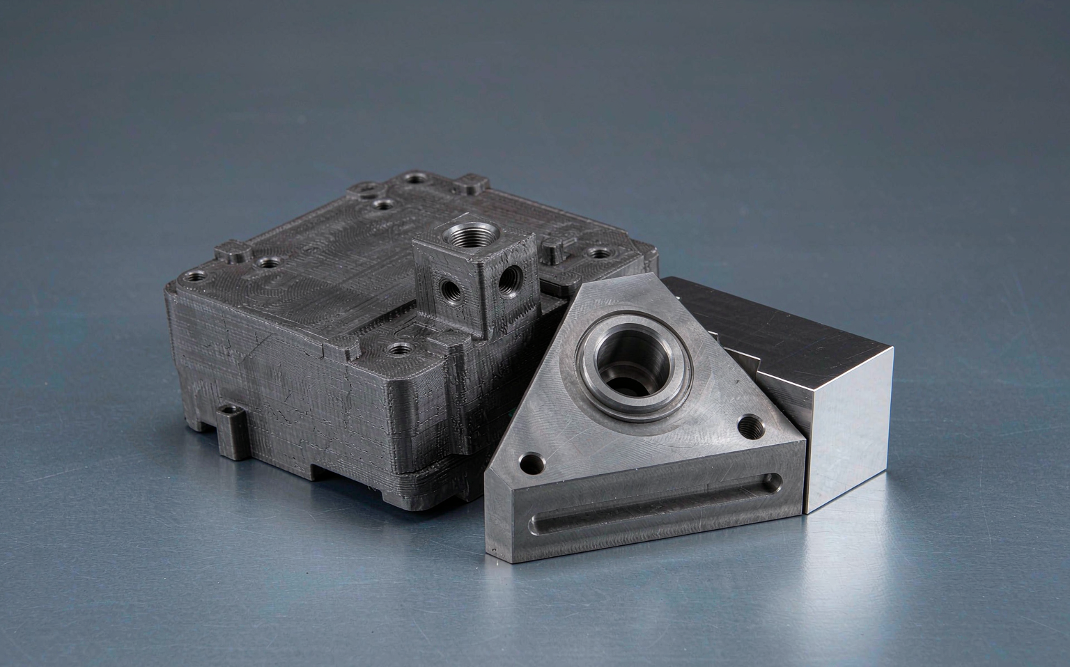
The realistic architecture for a functional AM component is usually near-net additive + subtractive finishing. Additive delivers the geometry no tool can reach; machining delivers the interfaces that have to fit, seal and locate. Designing for that combination is a different discipline from designing for either process alone.
What belongs in the additive stage
- Organic external form and load-path geometry
- Internal channels, lattices and voids
- Consolidated features that replace assemblies
- Lightweight structures and ribbing
What belongs in the subtractive stage
- Bearing bores and shaft fits
- Sealing faces and gasket seats
- Threads and threaded holes
- Datum features and precision locating surfaces
Four rules for hybrid AM + CNC design
- Add explicit machining allowance. Every face that will be cut needs stock — typically a fraction of a millimetre to a millimetre or more, depending on size, material and expected distortion. A part designed to net shape has nowhere to go when the print moves.
- Design datums that survive both processes. Choose datum features that exist in the printed geometry and remain reachable after support removal, so the same reference frame can be used for machining and inspection.
- Think about fixturing early. An organic AM shape is often hard to hold. Add temporary flats, bosses or clamp features that can be machined away, or design the part so it locates on surfaces that are themselves machined first.
- Sequence heat treatment correctly. Stress relief and heat treatment move dimensions. Machine critical features after the thermal step, not before it.
Why this matters commercially
A supplier that only prints will tell you the part is done. A supplier that prints and machines can tell you which features should not be printed at all — and that decision is usually where schedule and cost are actually saved. All six core processes — CNC machining, injection molding, mold making, 3D printing, die casting and sheet metal fabrication — are performed in-house under one ISO 9001:2015 quality system, so the hand-off between additive and subtractive happens under one quality system and one inspection plan.
Related: CNC Machining and Additive Manufacturing · CNC Machining Services · 5-Axis CNC Machining
When DfAM Is Not the Best Choice
A manufacturing partner who recommends additive for everything is not doing engineering. These are the cases where we will point you to a different process — and we run all of them in-house.
| Situation | Why additive struggles | Usually better |
|---|---|---|
| Very high production volume | No tooling to amortise means unit cost falls slowly with quantity; cycle time per part stays high. | Injection molding · Die casting |
| Tight tolerances across many features | As-printed accuracy is orientation-dependent; holding many features tight means many secondary operations. | CNC machining |
| Simple prismatic geometry | Nothing to gain from geometric freedom; bar or plate stock plus a few operations is faster and cheaper. | CNC machining |
| Flat or folded sheet components | Printing a flat panel is slow and dimensionally weaker than forming one from sheet. | Sheet metal fabrication |
| Commodity materials, cost-led design | AM feedstock costs more per kilogram than bar, plate or pellet; the premium has to be earned by geometry. | Conventional processes, matched to volume |
| Cosmetic Class-A surfaces | Layer texture and support marks require substantial finishing to reach a moulded appearance. | Injection molding |
The most useful outcome of a DfAM review is sometimes a recommendation not to use additive. That recommendation is free, and it is the same review you would pay for anyway.
Engineering Evidence and Documentation
Additive manufacturing is parameter-sensitive, so the documentation is part of the product. This is what we consider the minimum evidence package for a validated AM part — and what you should ask any supplier to provide.
Process traceability
Process, machine, material batch, build orientation, layer parameters and support layout recorded and repeatable for every production build.
Test coupons with the job
Coupons built in the same orientation and parameters as the production parts — not a separate build on a different day.
Inspection report
Functional dimensions measured and reported against the drawing, with the measurement method stated.
FAI on request
First article inspection reports per AS9102 are available on request for programmes that require them.
Certificates and test reports
Material certificates and test reports available on request; certificate copies can be provided under NDA.
Frozen parameters
Orientation and parameters captured in the release documentation, with any geometry change re-triggering validation.
On project data
We do not publish customer project results without written permission, and we do not publish illustrative numbers as if they were measured results. Project-specific measured data — material, size, process, tolerances, inspection method and lead time — can be shared for comparable applications on request, subject to customer approval and NDA.
Frequently Asked Questions
Each answer is written to stand alone, so you can lift any one of them without the rest of the page.
What does DfAM stand for?
DfAM stands for Design for Additive Manufacturing. It is the practice of designing or redesigning a component around the capabilities and constraints of a specific additive manufacturing process — build orientation, layer behaviour, support strategy, material anisotropy and post-processing — rather than simply making an existing CAD model printable.
What is the difference between DfAM and DFM?
DFM optimises a part for a conventional process such as CNC machining or injection moulding, where geometry is usually simplified for tool access or mould release. DfAM optimises for a layer-based process, where:
- geometric complexity can add value instead of cost
- build orientation governs strength, accuracy and surface finish
- support material, anisotropy and powder or resin evacuation become primary constraints
See the full DfAM vs DFM comparison table.
What are the main DfAM design rules?
The twelve core rules, in the order they should be applied:
- Select the AM process before finalising geometry
- Design around build orientation
- Control wall thickness
- Control overhangs and supports
- Design for anisotropy
- Define tolerance at the functional level only
- Avoid unnecessary large flat sections
- Fillet stress-critical internal corners
- Design holes and internal channels for the process
- Design for post-processing from the start
- Consolidate parts only where it adds value
- Validate before production
Why is build orientation important in DfAM?
Because it decides several outcomes at once: which surfaces need support, how layer interfaces sit relative to service loads, where stair-stepping appears, how tall the build is, and therefore how long and how expensive it is. Orientation is the single highest-leverage decision in a DfAM review — and it must be recorded on the released data, because a part validated in one orientation is not validated in another.
What is the 45-degree rule in DfAM?
It is a rule of thumb: surfaces overhanging at less than about 45 degrees from the build direction tend to need support material on many processes. Use it to shape early geometry — replace flat undersides with chamfers, and horizontal holes with teardrop profiles.
It is not a universal standard. The practical limit depends on the process, material, layer height, cooling and the length of the overhang. Confirm with a test build before release.
How does wall thickness affect 3D printing?
Walls that are too thin fail during build, cleaning or handling; walls that are unnecessarily thick add material cost, build time, residual stress and warpage risk.
As indicative starting points for design discussion: FDM around 1.0–1.5 mm, SLA around 0.5–1.0 mm, SLS and MJF around 0.7–1.0 mm. The practical minimum depends on machine, material, nozzle or laser parameters, wall height, orientation and required mechanical performance — confirm against the material datasheet and a test build.
How does anisotropy affect additive manufacturing design?
Layer-based parts are generally weaker across layers than within a layer, so tensile strength, fatigue life and impact resistance depend on how the part is oriented relative to its service loads. Design response: orient so primary load paths run within the layer plane, and validate with test coupons built in the same orientation as the production parts — never with coupon data from a different build direction.
Does DfAM apply to both metal and polymer 3D printing?
Yes, but the rules differ substantially. Polymer processes (FDM, SLA, SLS, MJF) are governed by wall thickness, support marks, resin drainage and powder removal. Metal powder bed fusion adds residual stress, thermal distortion, mandatory supports that also act as heat sinks, powder evacuation from internal channels, and post-build heat treatment that changes both properties and dimensions.
How does DfAM reduce 3D printing cost?
By changing decisions that are made in CAD:
- reducing build height, which usually drives machine time more than volume does
- removing unnecessary material through coring and ribbing
- minimising support volume through self-supporting geometry
- choosing an orientation that shortens build time and lowers scrap risk
- consolidating assemblies so fasteners and assembly labour disappear
- specifying post-processing only where it is functionally required
Should I redesign a CNC part before 3D printing it?
Usually yes, if you want the AM part to perform well rather than merely exist. Printing a machining-oriented design unchanged typically wastes additive's advantages and inherits its weaknesses — uniform thick walls that warp, tool-access geometry that adds material, and load paths that run across layer interfaces. At minimum, revisit orientation, wall thickness, overhangs and tolerance specification.
How do I design internal channels for additive manufacturing?
Provide at least two openings sized for the removal method, avoid dead ends and sharp turns that trap powder or resin, prefer teardrop or diamond cross-sections over circular horizontal holes so the channel stays self-supporting, keep the channel path smooth, and verify evacuation with a test build before production.
When should I use DfAM instead of CNC machining?
DfAM tends to win when the part has complex internal geometry, benefits from part consolidation or lightweighting, and is needed at low-to-medium volume or on a short iteration cycle. CNC machining is usually better when tolerances are tight across many features, geometry is simple, or unit cost at higher volume dominates the decision. In practice, many production parts use both: additive for the form, machining for the interfaces.
What files do I need to send for a DfAM review?
A 3D model in STEP, STL, IGES, OBJ, 3MF or a native SolidWorks or CATIA file, plus:
- material requirement, or the service environment if the material is not fixed
- quantity and expected repeat frequency
- functional dimensions, tolerances and fits
- surface finish requirements, by area where possible
- intended application and any certification requirements
Drawings are welcome wherever critical interfaces are dimensioned.
Get a DfAM Engineering Review
Have a STEP, STL, IGES or SolidWorks file? Send your CAD model and production requirements. Our engineers review process selection, wall thickness, build orientation, support strategy, tolerances and post-processing requirements before printing — and will tell you directly if conventional manufacturing is the better route for your part.
What you get back: a process and material recommendation, build orientation proposal, wall thickness and overhang notes, tolerance and post-processing guidance, a lead-time indication, and a quote. All drawings and models are treated as confidential; NDA available on request before file transfer. Response within 24 hours on business days.
Who This Guide Comes From
Founded in 1998, Xiamen Goldcattle Plastic & Metal Products Co., Ltd. is an OEM/ODM manufacturer running six core processes in-house. The additive recommendations in this guide are reviewed by the same engineers who machine, mould and inspect the parts afterwards.
1998OEM/ODM manufacturing in Xiamen, China
Certification held
- ISO 9001:2015 certified quality system
Certificate copies can be provided under NDA.
Process alignment & documentation
- IATF 16949 requirements supported
- ISO 13485-aligned process controls
- AS9100-aligned process controls
- FAI reports per AS9102 available on request
- ISO 14001-aligned environmental practices
Documentation packages, inspection reports and material certificates are available on request.
Lead times are quoted by production stage: prototypes 3–7 working days, low-volume 7–20 working days, mass production 15–25 working days. Minimum order quantity for prototypes is 1 piece. Customers in 100+ countries.