Process guide · thick-wall moulding
Gas-Assisted Injection Molding: When a Hollow Channel Beats a Solid Wall
A thick section is usually there for stiffness, not because the part needs to be solid. Gas assist puts a controlled hollow channel inside that section, so the part keeps its shape, loses weight and stops sinking on the visible face. The engineering is in the channel, the gas entry and the pressure profile — and every one of them can fail in a way that only shows up on a section.
Scope of this page, and of our capability
Gas-assisted moulding needs a gas-injection control unit, a nitrogen supply, a mould built around a designed channel and a process window established on real trials. It is not a setting that can be switched on inside an existing tool, and a conventional moulder cannot quote it credibly without those three things.
On our own position, stated plainly: we have delivered gas-assisted moulded parts — one such programme is our gas-assisted automotive handle. We do not publish machine counts, clamp tonnage, gas-pressure ranges, cycle times or capacity for this process, because we will not put a number on a page that we cannot evidence. If your project depends on a specific figure of that kind, ask in the review and you will get a direct written answer against your part.
This page is therefore written as an engineering and selection guide: how the process works, what a channel has to look like, how it fails, what it costs and what to demand from any supplier — ours included.
At a Glance
Four Injection Sequences, Not One Process
Short answer: “gas-assisted” covers four different sequences. They use the same physical trick — gas displacing melt — but they need different tooling and they fail differently. Knowing which one a supplier proposes tells you what the tool will look like, and what you are paying for.
Short shot
The cavity is deliberately under-filled, then gas is injected through the sprue or a gas pin and pushes the remaining melt to fill the part while opening a channel through the thick section. Gas pressure is held during cooling, then vented before ejection. The most common route for thick handles and frame parts.
Full shot
The cavity is filled completely first, then gas is introduced into the thick region and displaces material back into the machine or into an overflow. It gives tighter control over the filled volume, at the cost of higher injection pressure and a more demanding timing window.
Overflow cavity
Melt and gas are pushed into a secondary overflow well outside the part outline, which is trimmed off afterwards. It lets the channel be completed without starving the rest of the part, and it makes the gas path much easier to control — but it adds material, a trimming operation and tooling area.
Gas counterpressure
Gas is pre-charged into the cavity before injection, resisting the melt front. Used to suppress surface defects and hold a cosmetic face, particularly on large parts. A different control architecture from the three above, and rare in general job-shop work.
Which sequence applies is decided by the part, not by preference. A short shot needs a melt front that can be pushed; an overflow needs somewhere to put the excess; counterpressure needs a sealed cavity. Ask which one is proposed and why, and the rest of the tool design follows from the answer.
Gas Channel Design: The Part That Decides Everything
Short answer: the channel is a designed feature of the part, not a void that appears where the plastic was thick. If you cannot draw a continuous channel through the thick section that terminates inside material and never crosses a thin wall, the part is not a gas-assist part yet — and no amount of process tuning will make it one.
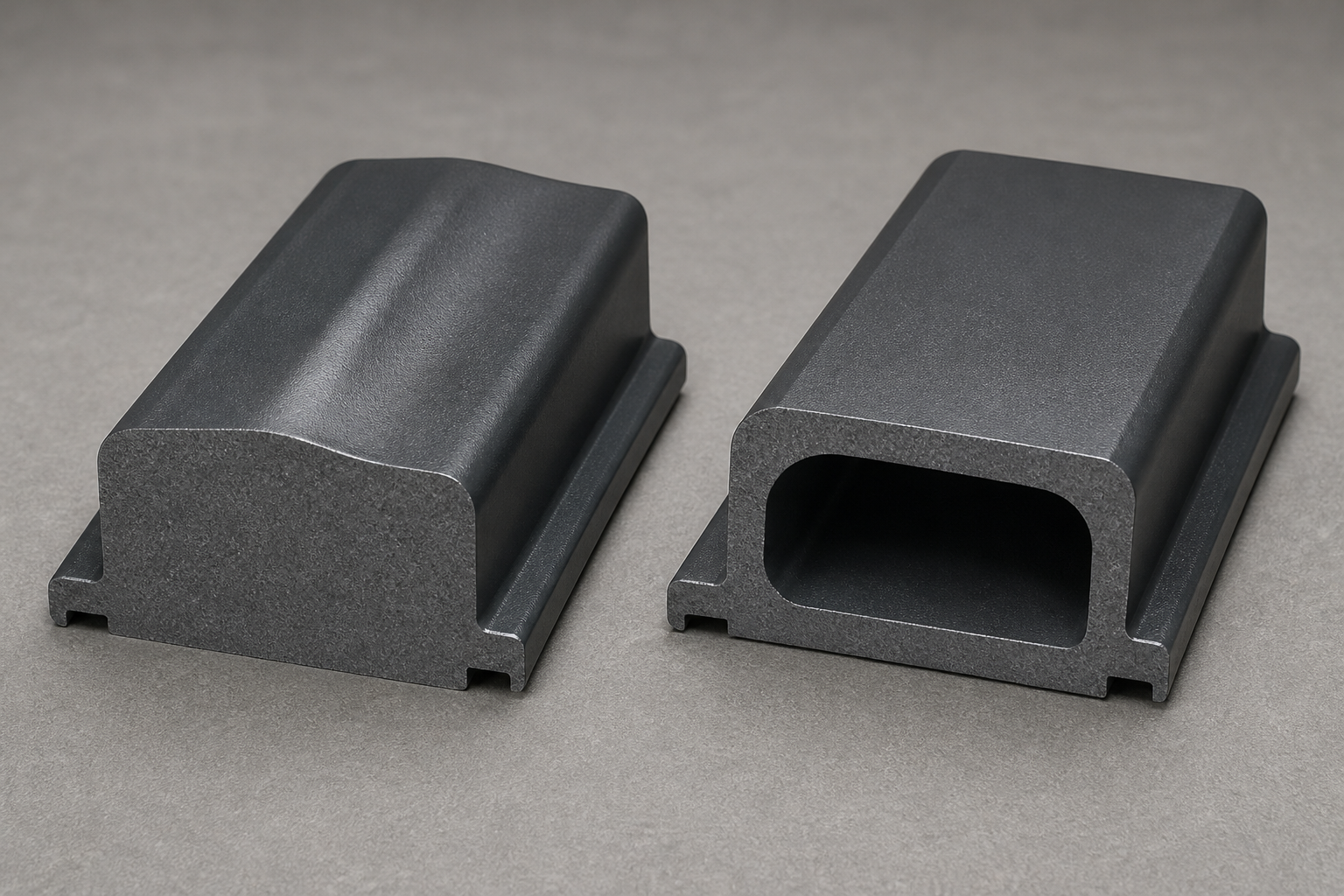
A channel works when three things are true at once: it runs through material thick enough to surround it, it is continuous from the gas entry to where the gas is meant to stop, and the wall left around it is close to even. The first draft of a channel usually fails on the second point, because designers route it by the shortest path between two thick bosses and inadvertently cross a thin rib on the way.
| Design factor | What it decides | What to check before the tool is cut |
|---|---|---|
| Channel path | Whether the gas has one controlled route or several competing ones | One continuous run through the thick section; no branches, no dead ends; the far end terminates inside material rather than at an edge |
| Channel size against wall | The wall thickness remaining around the void, and therefore cooling, stiffness and sink behaviour | The material left around the channel approximates your nominal wall, so the section behaves predictably instead of leaving a thin skin over a large void |
| Wall-thickness transition | Where the gas is tempted to leave the channel | Gradual transitions between thick and thin; a sudden step next to the channel is where fingering starts |
| Gas entry point | Where the pin or nozzle sits, and which face it marks | A non-cosmetic face, or a position that is trimmed or covered; the entry must feed the channel without a sharp turn |
| Venting and overflow | Whether displaced melt and displaced air have somewhere to go | Overflow well position if the sequence needs one; vents that do not become a gas leak path |
| Structural load path | Whether hollowing the section weakens the part where it is loaded | Bending and torsion paths identified; the void kept out of the highest-stress region, or the section deepened to compensate |
| Surface requirements | Which faces must stay unmarked | Cosmetic faces agreed in writing before gate and pin positions are fixed — moving either afterwards means re-cutting the tool |
Material Requirements That Are Specific to Gas Assist
Short answer: the grade has to hold a channel open while it cools, and not every grade in a family does. Melt strength, crystallisation behaviour and filler content matter more here than in conventional moulding, because the gas is relying on the melt to keep its shape.
| Material consideration | Why gas assist makes it matter more | What has to be confirmed |
|---|---|---|
| Melt strength | The channel walls must resist collapse while the gas is held and the polymer cools | Grade-specific behaviour; a high-flow variant of the same polymer may not hold the channel the standard grade holds |
| Crystallisation behaviour | Semi-crystalline grades shrink and stiffen differently from amorphous ones as they cool, which changes channel stability and final dimensions | Shrinkage allowance and channel stability assessed for the specific grade, not the family |
| Filler content | Glass or mineral fill raises stiffness but changes flow and can orient during filling | Whether the filled grade can form a stable channel, and whether the filler shows on a cosmetic face |
| Flow behaviour | Too easy-flowing a melt lets the gas run ahead and finger; too stiff a melt may not fill around the channel | Flow grade matched to the part's flow length and the channel geometry, confirmed on trial |
| Surface requirement | Filled and some engineering grades give a different as-moulded surface | Whether the cosmetic face and the grade are compatible at all — sometimes the answer changes the material choice |
Base resin data and the grades we hold are published separately on engineering materials; this section is deliberately limited to what changes when gas is added. Where a project needs a specific grade, send the grade rather than the family — “PA66” is not enough to assess channel stability, and a 30% glass grade will behave differently from an unfilled one in the same tool.
Five Gas-Specific Defects, and How They Are Actually Verified
Short answer: the failures that matter in gas assist happen inside the part, so the outside face can look perfect while the section is wrong. Verification has to be destructive or through-wall, and it has to be agreed before the first trial — not after a dispute.
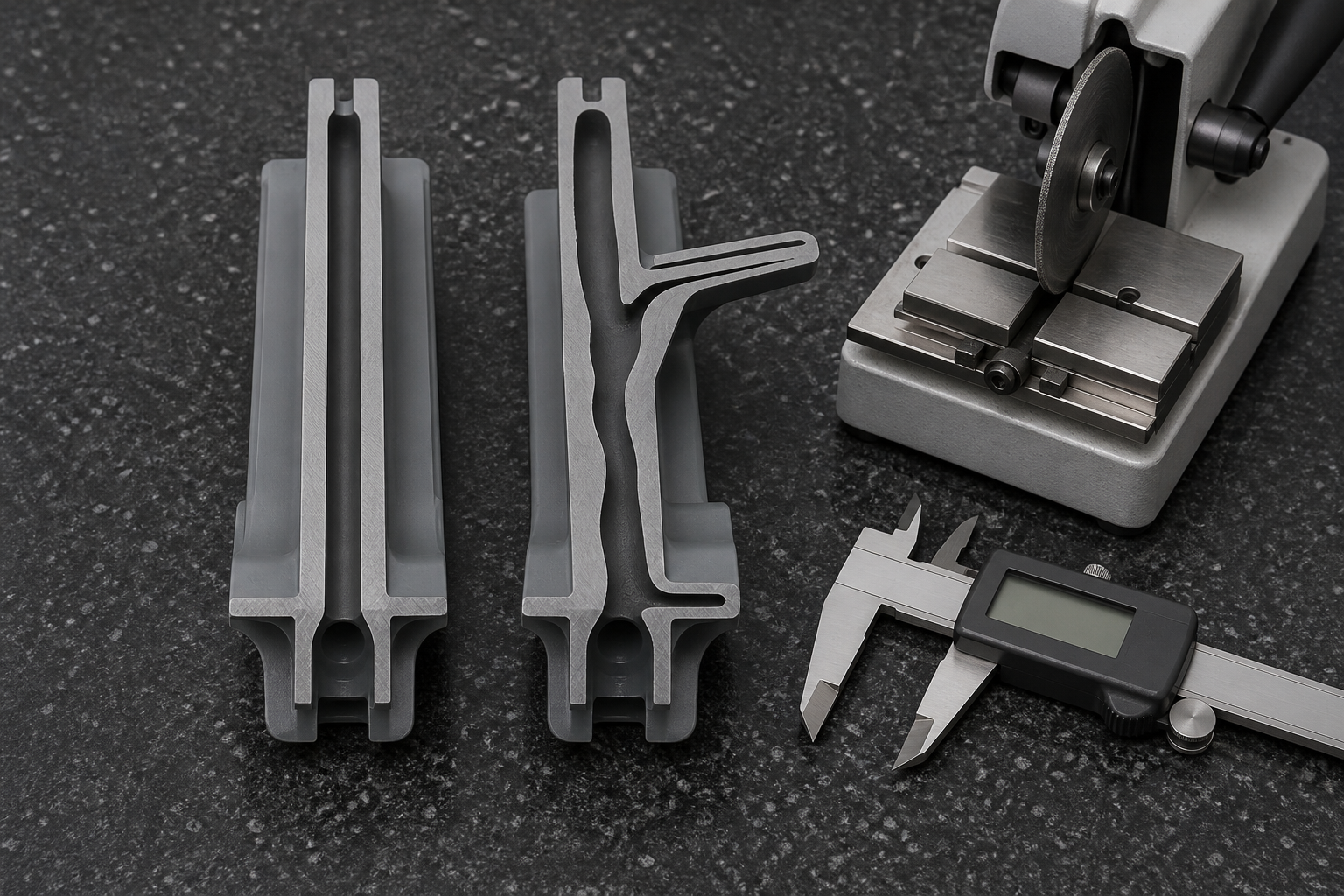
| Defect | What has happened | How it is detected | Direction of the fix |
|---|---|---|---|
| Gas fingering | The gas has left the channel and run into a thinner region that offered less resistance | Sectioning across the suspect zone; weight comparison against the calculated solid mass; scanning where available | Re-route or resize the channel, soften the wall transition, change gas timing and pressure |
| Blow-through | Gas has broken through the remaining wall and reached the surface, or come close enough to blister it | Visual inspection at the thinnest point, sectioning, pressure-decay check on a sealed part | More material over the channel, lower gas pressure, move or re-time the gas entry |
| Uneven channel | The void is not where it was designed to be, so wall thickness around it varies along the part | Sectioning at several stations along the channel, not just one; dimensional check for warp that follows the thin side | Channel geometry and wall balance; check the melt front is arriving evenly |
| Surface void or permeation | Gas has migrated or a void sits just under the skin, showing as a blister or a dull patch | Visual under raking light, sectioning at the mark, leak test where the part is sealed | Material and pressure profile; sometimes the grade is the limit, not the tool |
| Residual sink or warp | The channel did not relieve the thick section enough, or relieved it unevenly | Appearance check on the cosmetic face, dimensional and flatness check after cooling | Deeper or better-placed channel, hold pressure and time, cooling balance |
What verification actually looks like
Every method above has a cost and a limit, so the right set is chosen per part and written into the approval before tooling starts:
- Sectioning — cut the trial part and photograph or measure the void. Definitive, and it destroys the sample, so it is done on designated parts at agreed stations.
- Weight comparison — weigh the part against the solid mass the model implies. Fast, non-destructive, and it catches a channel that failed to form at all.
- Short-shot ladder — step the fill and gas timing to see where the channel forms and where it stops. A development tool, not an acceptance test.
- Through-wall scanning — where the part justifies it, to see the void without cutting. Needs an agreed sampling plan and a capable supplier.
- Pressure decay or leak test — where the hollow section is meant to be sealed and the function depends on it.
- Dimensional and flatness check after cooling — because a channel that is off-centre shows up as warp rather than as a visible defect.
Gas Assist Against the Alternatives
Short answer: gas assist is one of six ways to take mass out of a part or to stop a thick section sinking, and it is rarely the first one to evaluate. Ribs and geometry are cheaper; thin walls are cheaper again if the part tolerates them. Gas assist earns its tooling when a thick section has to stay thick for a reason.
The four-way comparison of thin-wall, gas-assist, foam and ribbed geometry is covered in detail on our thin-wall injection molding page and is not repeated here. What follows is the purchasing layer: which route to evaluate first, and what each one does to the tool and the part.
| Route | Evaluate it when | What it does to the tool | The trade you are accepting |
|---|---|---|---|
| Geometry and ribs | Stiffness is the real requirement and mass is a proxy for it | Usually the cheapest change — often no new tool if caught before design freeze | Rib junctions create thick sections of their own, and sink on a cosmetic face if proportions are wrong |
| Thin wall | Walls are uniform and the part can be run at higher pressure | Higher clamp force, tighter process window, more demanding tool | Narrow process window; not achievable where a thick section is functional |
| Gas assist | A thick section must stay thick, and a continuous channel can be designed through it | Purpose-built tool with channel, gas entry, sealing and venting or overflow | Tool cost and process development; the void must be verified, not assumed |
| Structural foam | Large flat parts where thickness gives stiffness and weight is the problem | Different process and often a different machine | Surface finish changes and mechanical properties are not equivalent to solid material |
| Blow moulding | The part is essentially a hollow shell from the outset | Entirely different tooling route | Loses the fine features and dimensional control of injection moulding |
| Assembly from simple parts | Volume is low or the geometry can be split | Low tooling, more part numbers | Assembly labour, joint tolerance stack-up and a weaker structure |
Gas assist and blow moulding are routinely confused because both involve gas and a hollow result. They are not interchangeable: gas assist hollows a section inside an injection-moulded part that keeps its detail and tolerance, while blow moulding makes the whole body a shell. A part with fine features and one thick handle is a gas-assist candidate; a container is not.
What Drives Cost in a Gas-Assist Project
Short answer: the saving is in material and weight; the cost is in the tool, the gas system and the iterations needed to prove the channel. A project only pays when the annual volume is large enough to absorb that, which is why the volume forecast matters more here than the unit price of resin.
| Cost driver | How it moves the project |
|---|---|
| Purpose-built tool | Channel, gas entry, sealing, venting and any overflow well are designed in. This is a different tool from a conventional one, and it cannot be adapted from an existing tool |
| Gas system and nitrogen supply | Whether the moulder already runs gas assist changes the route entirely — it is equipment and process capability, not a consumable |
| Channel and overflow design effort | Channel length, branches, wall transitions and load paths all add engineering before a chip is cut |
| Development iterations | A channel that fingers on the first trial is normal; the cost is in the trials and the tool changes, not the resin |
| Verification | Sectioning, scanning, weight comparison and leak testing all have cost, and the sampling plan determines how much |
| Material actually saved | Real, but it must be measured against the solid mass — and it is smaller than a first estimate usually assumes, because the wall around the channel still has to be there |
| Cycle time | A hollow section cools differently from a solid one; the effect on cycle can go either way and has to be measured on the tool |
| Annual volume | The fixed cost is spread over the programme. The same tool is uneconomic at low volume and attractive at high volume — this is the variable that decides the project |
What to Ask Any Supplier Before You Award a Gas-Assist Tool
Short answer: ask for evidence that the process is running, not for a description of the process. Gas assist is easy to describe and hard to run, and the difference shows up in exactly the areas below.
| What to ask | What a credible answer looks like | What should make you pause |
|---|---|---|
| Which gas system is used | A named control unit and nitrogen supply, and how pressure and timing are programmed | No equipment identified, or gas assist described as a machine setting |
| Which sequence they propose for your part | A specific choice out of short shot, full shot, overflow or counterpressure, with the reason | “We will decide at trial” with no channel concept |
| Channel design capability | A marked-up channel path on your model, with the wall left around it and where the gas stops | A promise to “optimise by simulation” with no channel drawn |
| Trial records from a comparable part | Section photographs or scans of a similar thick-wall part, with what went wrong and what changed | Only finished-part photographs, which cannot show the void |
| How the void is verified | A named method — sectioning, scanning, weight comparison, leak test — and who pays for it | Verification limited to visual inspection of the outside |
| Who carries the process risk | Clear terms on trial rounds, tool changes and who pays when the channel does not form | Tool payment in full before a validated section exists |
| Tool ownership and transfer | Written ownership, and what happens to the tool if you move the part | Ownership left unstated because it is “standard practice” |
These questions apply to us as much as to anyone else. Our own position on equipment figures is stated at the top of this page: we will not publish a number we cannot evidence, and we will answer the specific question in writing during the review.
What to Send for a Gas-Assist Feasibility Review
Short answer: a conventional RFQ is not enough, because the decision depends on where the thick sections are and which faces must stay unmarked. The extra inputs below are what turn a quote into a feasibility answer.
| Input | Why it changes the answer |
|---|---|
| 3D model and 2D drawing with wall thicknesses | The channel can only be routed through material that exists; a thickness map is the first thing reviewed |
| The sections you believe are too thick, and why | Distinguishes a functional thick section from one that could simply be cored or ribbed out |
| Resin grade, not just the family | Melt strength and filler content decide whether a channel holds |
| Cosmetic faces | Fixes where a gas pin, gate or overflow may land — and whether the part is a candidate at all |
| Weight target or permissible hollow ratio | Turns “make it lighter” into a design constraint that can be checked |
| Mechanical loads and load paths | Determines where the void must not go |
| Annual volume and programme life | Decides whether a purpose-built gas-assist tool is economic at all |
| Verification you will require | Sectioning, scanning or leak testing drives both the trial plan and the cost |
| Target date and any current-process problem | Establishes whether gas assist is the fix, or whether the current defect has a cheaper cause |
The conventional RFQ inputs — tolerances, surface finish, secondary operations, packaging and delivery terms — are covered on our injection molding quote page and are not repeated here.
Frequently Asked Questions
What is gas-assisted injection molding?
It is an injection moulding variant in which pressurised inert gas, usually nitrogen, is injected into the melt so that it displaces material through a designed channel and forms an internal hollow section inside a thick region of the part. The gas also holds pressure against the mould wall while the polymer cools.
What parts are suitable for gas-assisted molding?
Parts with a genuine thick section that can carry a continuous channel: thick grab handles and door pulls, thick ribs and bosses, tubular or frame-like structures, and large parts where a thick section would otherwise sink or warp. The part must also have somewhere for the gas to enter and a load path that tolerates a void.
How does gas-assisted molding reduce sink marks?
A sink mark appears where a thick section shrinks after the surface has solidified. When gas displaces material from the centre of that section and holds pressure during cooling, the effective wall thickness around the cavity is reduced and pressure is maintained, so the outer face is less likely to draw in. It reduces the risk; it does not remove the need to design the section properly.
What is gas fingering?
Gas fingering is when the gas leaves the intended channel and runs as a narrow finger into a thinner region, because that path offered less resistance. It produces an uncontrolled void, local thinning and sometimes a visible surface defect. It is controlled by channel geometry, wall-thickness transitions and the gas pressure and timing profile.
Does gas-assisted injection molding require special tooling?
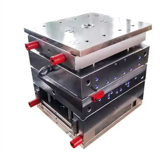
Yes. The tool needs a designed gas channel, a gas injection point such as a gas pin or nozzle, sealing where the gas is introduced, and often an overflow well or venting arrangement depending on the sequence used. The mould is purpose-built for the process rather than adapted from a conventional tool.
Which plastics can be gas-assisted molded?
Gas assist is used with commodity and engineering thermoplastics, including PP, ABS, PC/ABS, PA and PBT, and with filled grades. Suitability depends on the specific grade: melt strength, crystallisation behaviour, filler content and the required surface all affect whether a stable channel can be formed, so the grade has to be assessed rather than assumed from its family.
How much does gas-assisted injection molding cost?
Cost is driven by the purpose-built tool, the gas system and nitrogen supply, channel and overflow design, trial iterations, sectioning or scanning verification, the material actually saved, cycle time and volume. There is no meaningful per-part figure without a specific part, so a project is quoted from a drawing and a demand forecast.
Is gas-assisted molding better than blow molding?
They solve different problems. Gas assist creates a controlled internal channel inside an otherwise injection-moulded part that keeps its detailed features and dimensional accuracy. Blow moulding makes a part whose whole form is a hollow shell. A part with fine features and one thick section is a gas-assist candidate; a bottle or a large hollow shell is not.
How do I evaluate a gas-assisted molding supplier?
Ask for the gas injection equipment and nitrogen supply actually used, the pressure and timing control available, a channel design review of your part, trial records from a comparable thick-wall part, and the method used to verify the internal void, such as sectioning, scanning or weight comparison. Ask who owns the tool and who carries the process risk.
What should I include in a gas-assist RFQ?
A 3D model and 2D drawing with wall thicknesses, the intended thick sections and where a channel could run, the resin grade, cosmetic faces, permissible internal void or weight target, mechanical loads, annual volume, the verification you will require and the target date. State which surfaces must remain unmarked by a gas pin or gate.
Related Pages
| Page | What it covers |
|---|---|
| Custom injection molding services | The general moulding capability, process flow and quality approach |
| Thin-wall injection molding | Thin-wall versus gas-assisted and foam, compared as lightweighting routes |
| Custom plastic components | Part types produced, and how the process is chosen for each |
| Injection mold making in China | Tool design and manufacture, including special-purpose tools |
| Overmolding services | Applying a second material over a substrate — a different route to a multi-material part |
| Engineering materials | Resin families, grades and property data |
| Quality certifications | Quality system and certification status |
| Injection molding quote | Standard RFQ inputs, cost structure and quotation process |
Send a Thick-Wall Part for a Channel Review
If your part has a section that is thick for a reason, send the model and the wall thickness map with the cosmetic faces marked. The review will tell you whether a channel can run through it, where it would finger, and whether gas assist is the cheapest route to the result you need — including the cases where it is not.
What this page does and does not claim
This page explains a process and how to select it. It is not an offer of a specific machine, tonnage, pressure range, cycle time or capacity for gas-assisted moulding, and it deliberately publishes no such figures, because we cannot evidence them for publication. The capability statement is limited to what is verifiable and is linked to the part programme it refers to.
No tooling prices, unit prices, weight-reduction percentages or yield figures appear here. Where a figure would be needed to answer a real question, the answer is given against a specific part in a review. Process descriptions are written at the level of principle; actual setpoints are established on the tool.
Technical content is reviewed before publication and the page carries a revision date. If you find something here that contradicts your own experience, tell us — on a page about a process where the failure is invisible until you cut the part open, being corrected is worth more than being agreed with.