CNC Machining · Hole Making
CNC Boring Cycles: G85, G86, G89 and the Codes That Resemble Them
A boring cycle is usually explained by its number and its name. Neither one is reliable. The same number is a different cycle on a different machine, and two codes with different names accept an identical address list. What actually defines the motion is which addresses the block accepts and what the control does at depth.
Request a boring review on your drawing Drawing, material, bore size and depth are enough to start.
Scope of This Page, and the Part of Hole Making It Owns
Short answer: this page covers the boring canned cycles themselves — G85, G86, G89, G76 and G77 — the addresses each one accepts, the action each performs at depth, and what changes when the same number appears on a different machine. It does not re-explain how to choose between drilling, reaming and boring, and it does not restate hole metrology. Two neighbouring pages in this cluster already do both, in more detail than a single page can.
The division is deliberate rather than cosmetic. The cluster already carries a drilling guide that covers how a hole-making process is chosen, a page that covers the drilling cycles G81, G73 and G83 address by address, and a hole quality guide that covers diameter, position, form, surface and burrs. What none of them covers is the boring family: the string G85, G86, G89, G76 or G77 does not appear anywhere on those three pages. That absence is the reason this page exists, and it is also the reason this page does not repeat their material.
So if your question is which process should make this hole, or how do I prove the hole is good, the answer is on those pages and the links are in the last chapter. If your question is what does this block actually command, and why did the bore come out with a score line, it is here.
What the Term Covers, and Why Three Different Things Are Called the Same Name
Short answer: "boring cycle" is used for three separate things — boring as an operation, a boring canned cycle as a block of stored motion, and the boring tool itself. Almost every confused explanation of the subject is a category error between the first two.
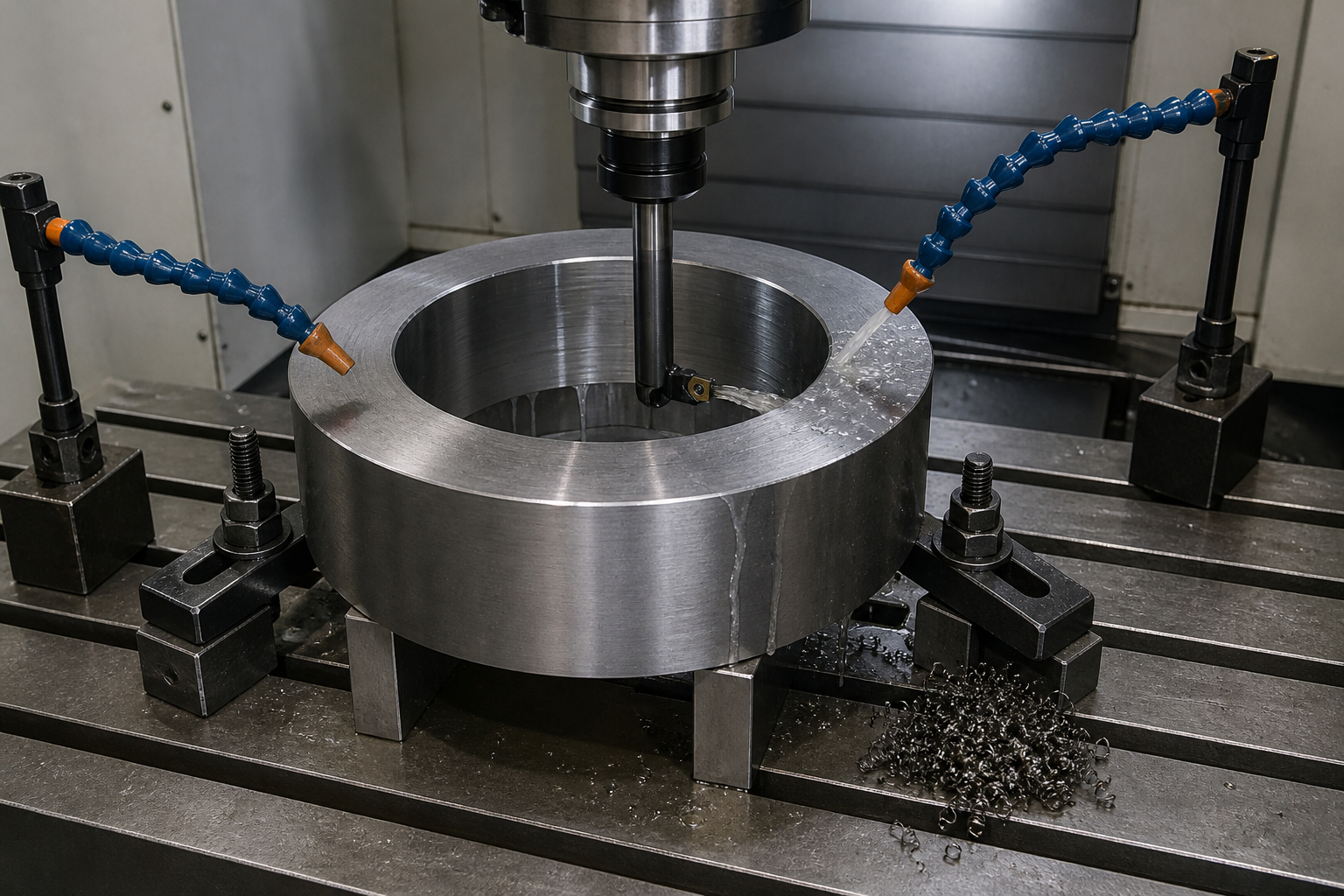
The operation is single-point machining of an existing hole. A rotating or stationary tool with one cutting edge is offset to a set radius, fed along the hole axis, and removes a continuous chip from the full circumference. That is a machining strategy, chosen because the hole needs a size, a position or a form that the previous operation did not deliver.
The canned cycle is something else entirely. It is a macro stored in the control and invoked by one block. It does not decide the strategy, choose the tool or set the radius. It automates the repetitive part — approach to a reference plane, feed to depth, perform a fixed action at depth, retract — and then repeats at every subsequent position until it is cancelled. On the reference used here, the boring cycles and the drilling cycles all sit in modal Group 09, which is why one of them cancels another and why G80 cancels the family.
The tool is the third referent: a boring bar or a boring head, the physical object that carries the insert and sets the radius. It is the only one of the three that changes the diameter of the hole.
That last point is the thread running through this page. The cycle's real contribution is the exit — and the exit is where a bored hole most often acquires the mark that gets it rejected.
Read the Addresses, Not the Number
Short answer: the address list is a more reliable identifier than the code number or the name. Each address is a piece of information the block must accept, and the set of addresses reveals what the cycle is mechanically able to do — whether it dwells, whether it shifts radially, whether it pecks.
The table below reproduces the address lists published for one widely used mill control, with the titles exactly as that reference states them. It is a worked example of how to read a control's documentation, not a universal table: the point of the exercise is the method, and the method transfers to any control whose manual lists its addresses.
| Code | Title in the reference | Addresses accepted | What the address set proves |
|---|---|---|---|
G81 | Drill Canned Cycle | E F L R X Y Z | Drilling: no dwell, no radial shift, no peck control |
G82 | Spot Drill Canned Cycle | E F L P R X Y Z | Drilling with a bottom dwell |
G73 | High-Speed Peck Drilling Canned Cycle | F I J K L P Q R X Y Z | Drilling with peck control — the longest list, and the least precise |
G85 | Bore In, Bore Out Canned Cycle | F L R X Y Z | Boring, no dwell, no shift |
G86 | Bore and Stop Canned Cycle | F L R X Y Z | Same address set as G85 — the difference is a fixed action, not an address |
G89 | Bore In, Dwell, Bore Out Canned Cycle | F L P R X Y Z | Boring with a bottom dwell |
G76 | Fine Boring Canned Cycle | F I J L P Q R X Y Z | Boring with dwell and a radial shift |
G77 | Back Bore Canned Cycle | F I J L Q R X Y Z | Boring with a radial shift and no dwell |
Three things fall out of that table, and they are the three things most secondary explanations get wrong.
First, G85 and G86 are indistinguishable from the block. They accept exactly the same addresses. Nothing in the program text says which one will stop the spindle. The difference is a fixed action the control performs at depth, documented in prose rather than in the parameter list — which means a reader who scans only the address list, or only a summary table, cannot tell them apart. This is the strongest argument for reading the control manual rather than a blog.
Second, G76 and G77 differ by exactly one letter: P. Both shift radially. Both accept I, J and Q for that shift. Only G76 accepts P, and P is a dwell at the bottom of the hole. That single missing address is the whole difference between a fine boring cycle and a back boring cycle, and it is invisible if you compare the two by name.
Third, a long address list is not a measure of quality. G73 accepts the most addresses of any cycle in the table and is a roughing drilling cycle. G85 accepts five and is a boring cycle. Counting parameters tells you how much control the programmer has over the path, not how good the hole will be.
The Four Decisions Inside Every Boring Cycle
Short answer: any boring cycle can be fully described by four decisions — how the tool enters, what it does at the bottom of the hole, how it leaves, and whether the cutting edge is still touching the wall while it leaves. The fourth decision is the one that decides whether the bore is accepted.
| Cycle | Entry | At the bottom | Exit | Edge in contact on exit? |
|---|---|---|---|---|
G85 | Feed to depth | Nothing | Feed out | Yes, at feed rate |
G86 | Feed to depth | Spindle stopped | Retract | Yes, without rotation |
G89 | Feed to depth | Dwell for P seconds | Feed out | Yes, at feed rate |
G76 | Feed to depth | Dwell, then radial shift | Retract | No — cleared by the shift |
G77 | Shift in below the shoulder | Nothing | Shift back, then retract | No — cleared at both ends |
Read down the last column. Three of the five cycles leave a loaded cutting edge against the finished wall while the tool is still moving. That is not a defect in the cycles; it is the reason the feed rate on the way out, and the condition of the insert, matter more than most programmers assume. A bore that measures correctly and still fails inspection usually failed on this column.
The diagram below plots the four common cases as tool paths inside a sectioned bore, with the bar deliberately drawn against the wall it is cutting — which is where a single-point bar actually sits.
The rest of this page takes each cycle in turn and states what it is for, what it costs, and what to check if the bore comes out wrong. Two of the five are named for something they do not do: G85 is not a roughing cycle despite being the simplest, and G76 is not a tolerance grade.
G85 — Bore In, Bore Out
Short answer: the plain bore. Feed in at cutting feed, feed out at cutting feed, no dwell and no shift. It is the correct choice when the wall can tolerate a second pass of the insert and the bottom of the hole needs no clean-up.
Because the tool leaves at feed rate rather than in rapid, G85 is gentler on the wall than a rapid retract: the insert is still cutting, so any mark it makes is a feed mark rather than a gouge. That is the argument for it, and it is a real one. The counter-argument is that the insert is still cutting, so it is also still removing material on the way out — including the small amount that bar deflection added on the way in.
Bar deflection is why G85 pairs badly with a long overhang. The bar bends away from the wall under cutting force, so the diameter at depth is slightly smaller than the diameter at the entry. On the way out, the same bar is now cutting a wall that is a few micrometres larger than the path it just took, and the load changes. The result is a bore that measures correct at the entry, tight at the bottom, and carries a faint helical witness line where the tool re-entered the cut.
There is nothing to tune inside the block. G85 accepts F, L, R, X, Y and Z on the reference used here, and none of those addresses changes the exit behaviour. If the exit needs to change, the cycle has to change.
G86 — Bore and Stop
Short answer: feed in, stop the spindle at the bottom, then retract. It exists for the case where a spinning insert must not drag a mark on the way out — and it introduces a failure mode of its own that the manual warns about in capital letters.
The published caution on this cycle is worth quoting rather than paraphrasing, because it is a crash warning and not a style note: unless the program specifies otherwise, the cycle uses the most recently commanded spindle direction, and if no direction was specified before the cycle, the default is clockwise. If M05 is in effect, the cycle runs as a no-spin cycle. The manual states plainly that this lets you run applications with self-driven tools but can also cause a crash.
Read that again as a programmer: the block does not contain a spindle command. It inherits one. A boring cycle that ran correctly yesterday can run backwards today because an earlier operation in the program left M04 modal, and nothing in the boring block looks wrong. On a single-point boring bar, a reversed spindle is not a subtle problem — the insert is oriented for one direction of rotation, and running it backwards loads the wrong face.
The check that costs nothing: put an explicit spindle command immediately before the boring block, every time, even when the previous line already set it. A redundant M03 is free. Diagnosing a scrapped bore because an operation eight blocks earlier changed the modal spindle state is not.
Mechanically, G86 still leaves the insert in contact with the wall while the tool retracts. Stopping the spindle removes the rotational component of the mark but not the axial one, so the retract becomes a scrape along a single line rather than a helix. That is why this cycle is usually paired with a boring head that can retract or spring clear, and why it is a poor match for a rigid bar in a deep bore.
G89 — Bore In, Dwell, Bore Out
Short answer: G85 plus a dwell at depth, set in P. The dwell gives the bottom of the hole time to clean up — and it is the only difference between the two cycles.
Where a blind bore needs a flat, square bottom, or where a through bore breaks into a cross-hole and the interruption needs to be smoothed, a dwell is the cheap answer. The insert keeps rotating at depth with no axial feed, so it wipes the bottom rather than cutting into it, and the corner cleans up.
The dwell has two costs. It rubs, which work-hardens some materials and dulls the insert corner faster than cutting does. And it is modal: the published note states that P values are modal, and that if a G04 Pnn or an M97 Pnn appears in the middle of a canned cycle, that P value will be used for the dwell as well as for its own purpose. So a dwell programmed earlier for a different reason can silently become the boring dwell.
G76 — Fine Boring Is a Dwell and a Shift
Short answer: G76 is the only cycle in this family that moves the cutting edge away from the wall before retracting. That is what "fine" describes — a retract strategy, not a tolerance grade. It also takes both a dwell and a shift, which is why it accepts more addresses than any other boring cycle.
The published description is explicit: in addition to boring the hole, the cycle shifts the X and Y axes before retracting in order to clear the tool while exiting the part. The shift is programmed in Q, which is always incremental, or — when Q is not specified — in the optional I and J values, which determine both the direction and the distance.
Two consequences follow that are easy to miss and expensive to discover at the machine.
The program does not fully define the direction. When Q is used, the published note states that a machine setting — Setting 27 on the reference used here — determines the shift direction. So the same program, with the same Q value, can shift toward the wall or away from it depending on a parameter that lives in the control, not in the G-code. A program proven on one machine is not proven on another until that setting has been compared.
The shift needs somewhere to go. The tool moves radially before it retracts. In a blind bore with a flat bottom, or in a bore that ends against a shoulder, that radial movement has no clearance and the shift becomes a collision. This is a design question as much as a programming one: a fine-bored blind hole needs either a relief at the bottom or enough depth below the finished face for the tool to shift into.
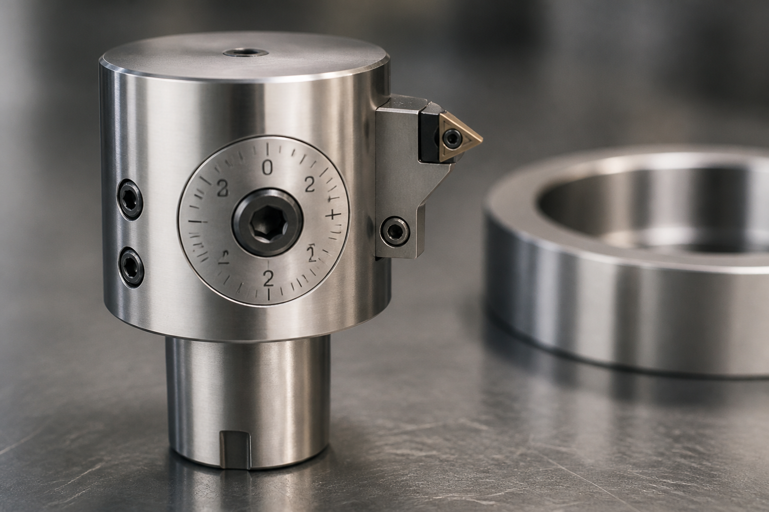
This is the cycle most often quoted in a supplier's marketing as evidence of capability, and the quotation is usually meaningless. "G76 fine boring" describes the retract path. Whether the bore holds a tolerance depends on whether the head was dialled in, whether the bar was rigid enough at that overhang, and whether the insert was fresh — three things the G-code line does not contain.
G77 — Back Boring, Where the Entry Is the Hard Part
Short answer: back boring machines a bore from the far side of a shoulder, so the tool has to pass through a smaller opening, shift out to cutting radius behind the shoulder, cut on the way back, then shift in again to leave. It is the only cycle here that shifts at both ends, and the only one with no dwell.
The published description confirms both shifts: the cycle shifts the X and Y axes before and after the cut, to clear the tool while it enters and exits the workpiece. Unlike G76, the address list contains no P — there is no dwell at depth, because there is no bottom of hole to dwell at. The "bottom" of a back-bored feature is a shoulder, and the tool is cutting toward it, not sitting on it.
Two details in the reference are counter-intuitive enough that they are worth stating plainly, because both cause real crashes.
| Detail | What the reference states | Why it matters |
|---|---|---|
R value | It is negative, and it must go past the bottom of the part for clearance | The reference plane for a back bore sits on the far side of the workpiece, not above it. A positive R copied from a normal boring cycle puts the approach plane in the wrong place entirely. |
| Return level | An initial point return (G98) does not need to be commanded; the control assumes it | The tool returns to the initial plane automatically, which is higher than an R plane. If the fixture or the clamp sits above the part, that return path is where the collision happens. |
Back boring also demands a tool the other cycles do not: a bar that can pass through the minor opening, then present an edge behind the shoulder. That geometry is a tooling decision made before the program exists, and it usually sets the minimum bore size for the feature. A drawing that specifies a back-bored diameter close to the through-opening diameter may simply have no tool that fits.
The Same Number on a Different Machine
Short answer: the number is not portable. On the reference used on this page, G76 is a fine boring canned cycle in Group 09 on the mill and a multiple-pass threading cycle in Group 00 on the lathe. Same number, same manufacturer, two unrelated operations.
That single example is the whole argument against treating any G-code table as universal, and it is verifiable in about a minute on the manufacturer's own reference: the mill entry and the lathe entry for the same code describe different cycles, in different modal groups, with different addresses. G76 on the lathe takes A, D, K, U and W for thread angle, first-pass depth, thread height and incremental diameter and length — addresses that mean nothing in a boring context. The lathe G76 also has its own set of control settings for chamfer size and angle.
For a buyer reading a supplier's process description, the practical consequence is this: a statement like "we use G76 fine boring on our lathes" is, taken literally, a statement about thread cutting. It may well be a loose description of a boring operation performed on a lathe with a different code, and it may be perfectly competent work — but the code quoted does not support the claim. The question to ask is not which code, but which machine, which tool, and what the first-article report measured.
G85 from G86.Seven Programming Faults That Scrap Bored Holes
Short answer: none of the seven faults below is a mistake in the geometry of the cycle. All seven are state faults — something set earlier in the program, or in the machine, that the boring block silently inherited. They are listed in the order they tend to appear during proving.
| Fault | What you see | The check |
|---|---|---|
| Spindle direction inherited from an earlier operation | Bore runs backwards, or does not rotate at all; insert corner breaks on one side | Command the spindle direction explicitly in the block before the cycle, every time |
Modal P left over from a G04 or M97 | Bottom dwell is longer or shorter than the program says | Search the program for every P address before the cycle; re-state P in the boring block |
Q read as a bore diameter | Bore oversize, or the shift is far larger than intended | Q is a radial shift distance, always incremental — not a diameter and not a radius callout |
| Shift direction taken from a machine setting | The program that worked on the proving machine shifts the wrong way on a second machine | Compare the setting that governs shift direction between machines before running the program |
| Cycle left active after the last hole | The next positioning move is interpreted as another hole, often in a clamp | Cancel the cycle with G80 immediately after the last bore, before any move that is not a hole |
R plane set from the wrong reference | Rapid approach into the fixture, or a wasted approach of no value | R is measured from the part surface as defined in the work offset — confirm that surface before trusting the value |
| Dry run at full feed override, without single block | First-article collision that the dry run was supposed to prevent | Dry run with rapid override reduced and single block active; the boring block is where overrides stop protecting you |
The first, second and fourth rows share a cause: they are all values that live outside the boring block and are consumed by it. That is a structural property of canned cycles, not an oversight by any one control builder. The cycle is designed to be short, and shortness is achieved by inheriting context. The programmer's job is to make the inherited context explicit at the point it matters.
Why the Cycle Is the Smallest Variable in the Chain
Short answer: because the cycle changes the path the tool takes, and nothing else. It does not change the force on the bar, the stiffness of the bar, the sharpness of the insert, the geometry of the machine or the condition of the pre-machined hole. In any list ordered by influence on the finished bore, it belongs last.
That ordering is worth stating explicitly, because the way the subject is usually discussed implies the opposite — as if choosing the right cycle were the engineering decision and the rest were detail.
| Rank | Variable | Why it dominates |
|---|---|---|
| 1 | Condition of the pre-machined hole | Stock allowance, straightness, position and surface condition. Boring removes what is there; it cannot add material back to a hole that is already oversize or off-centre. |
| 2 | Bar stiffness at the actual overhang | Sets deflection, and therefore taper, chatter and the achievable depth in one move. |
| 3 | Insert geometry and wear state | Corner radius, rake and edge condition set the cutting force and the surface the wall receives. |
| 4 | Machine geometry and positioning accuracy | Sets where the bore lands, and how much of a position error boring can still correct. |
| 5 | Coolant delivery and chip evacuation | Recut chips score the wall and raise the temperature of the bar, which changes its length. |
| 6 | Cutting data | Matters, but acts through ranks 2 to 5 rather than independently of them. |
| 7 | Cycle selection | Changes the exit path and the bottom-of-hole action. Does not change diameter, roundness or wall quality except through the exit. |
Read the table the other way and it becomes a diagnostic sequence. When a bore is out, the productive question is not "which cycle should this be" but "where in this list does the error live". A taper points at rank 2. A bore that is round but off position points at rank 4. A wall with a single helical score points at rank 1, 3 or 5. Only a mark that appears uniquely at the exit points at rank 7 — and that is the one case where changing the cycle is the right answer.
The Bar Is a Cantilever, and That Explains Most Bore Defects
Short answer: a boring bar is a beam fixed at one end and free at the other, loaded sideways at the tip by the cutting force. Its stiffness falls with the cube of overhang and rises with the fourth power of diameter, so small changes in how far it hangs out matter far more than any programming choice.
The standard cantilever relation gives tip deflection proportional to L³ over d⁴, where L is overhang and d is bar diameter. The consequences are worth working through as arithmetic rather than adjectives:
- Double the overhang and the deflection at the tip rises by a factor of eight. This is why a bar that is stable at one depth becomes marginal at double that depth, with no other change.
- Increase bar diameter by 20 percent and stiffness rises by about a factor of two, because the ratio enters at the fourth power. This is why the first fix for a ringing bore is a bigger bar, not a slower feed.
- Reduce the depth of cut and the cutting force falls roughly in proportion, so deflection falls too — but the material removal rate falls with it, and the deflection that remains still produces the same taper shape, just smaller.
This is the mechanism behind the most common bore defect there is: a bore that is on size at the entry and tight at the bottom. The bar bends away from the wall as it advances, so the effective radius decreases with depth. The measurement that identifies it is a three-point check along the bore axis, not a single reading at the mouth.
It is also the mechanism behind chatter that appears only at depth. As overhang increases, the bar's natural frequency drops toward the tooth-passing and spindle frequencies, and the system starts to ring. A damped bar — one with a tuned internal mass — raises the effective damping and pushes that boundary deeper. It does not make the bar stiffer; it removes energy from the vibration. That distinction matters when a supplier claims a deep bore is possible: the question is not whether a damped bar exists in that diameter, but whether the setup was tuned for that depth.
G85, G86, G89, G76 or G77 that refers to stiffness, overhang or deflection, and no control that measures the wall and corrects the radius inside the cycle.What Each Process Can Actually Correct
Short answer: the useful way to separate hole-making processes is not by the quality they promise but by the error they can still remove. Boring is unusual because it is adjustable — it can change size, and it can move the hole within the machine's positioning accuracy. Reaming cannot.
| Process | Size | Position | Form | Note |
|---|---|---|---|---|
| Drilling | Creates the hole | Creates it, within drill wander | No | Sets the starting condition everything downstream inherits |
| Reaming | Yes, within a narrow band | No — follows the pre-hole | Partly | Multi-edge tool; it enlarges where the hole already is |
| Single-point boring | Yes, continuously adjustable | Yes, within machine accuracy | Yes | The only process here that relocates a hole by adjusting a radius |
| Helical interpolation | Yes, by tool path | Yes, within machine accuracy | Partly | Needs a control and a cutter that can produce a true circle |
| Honing | Very fine control | No | Yes, strongly | Improves form and finish; inherits position entirely |
The distinguishing row is position. A bore that is 0.05 mm off its datum cannot be rescued by reaming, because a reamer is guided by the hole it enters. It can be rescued by boring, because a boring bar is guided by the machine's positioning, and the operator can offset the radius to cut the wall on the side that needs removing. That is why boring appears in a process chain after drilling when position is critical, and why reaming appears after boring when size and finish are critical and position is already settled.
The detail behind each of these rows — depth limits, chip behaviour, parameter choice, and how the process chain is assembled — is covered in the drilling guide rather than restated here. This page's claim is narrower: it is the only one of the five that can move a hole.
When Boring Is the Wrong Answer
Short answer: boring is the wrong route when the error is in position and there is no stock to remove on the corrective side, when the bore is too deep for any bar in that diameter, or when the feature is better made by a process that does not need a rotating single-point tool at all.
| If the situation is | Boring is a poor fit because | Consider instead |
|---|---|---|
| Position is out and stock is already removed on the corrective side | Boring can only remove material; it cannot put a wall back | Rework the datum, or scrap and re-machine from a corrected pre-hole |
| Bore depth exceeds roughly a few diameters in a small size | No bar in that diameter is stiff enough at that overhang | Helical interpolation with a smaller cutter, or a damped bar if one exists in the size |
| Size and finish are the only requirements and position is already correct | Boring is slower than a multi-edge tool for the same result | Reaming |
| The bore crosses an existing cavity or an interrupted wall | The single-point edge is loaded and unloaded at every interruption | Interpolation, or accept the interruption and control it with a different insert geometry |
| The feature is a round hole in a flat plate, made in quantity | A boring pass adds a setup for a result a good drill and reamer already hold | Drill and ream, or punch if the material and volume suit it |
| The part is a turned component with an on-axis bore | Milling a coaxial bore is the long way round | Boring on a lathe — note that the codes and the cycle family differ from the mill |
What a Bored Hole Needs on the Drawing
Short answer: diameter with tolerance, depth and whether the hole is through or blind, position with datums, form only where the function needs it, surface finish, and the edge condition at both ends. Each of those is a separate instruction, and a drawing that omits one does not get it by default — it gets whatever the process happened to produce.
| Callout | What it forces | What happens if it is missing |
|---|---|---|
| Diameter and tolerance | Whether a single-point boring pass is required, and how the head is dialled in | The shop quotes to a house standard, and the part may not assemble |
| Depth, and through or blind | Whether a shift can be used at the bottom, and how much clearance the tool has | A fine boring cycle may be programmed into a bore with no room to shift |
| Position or position tolerance, with datums | Whether boring is used to correct the pre-hole, and from which datum the offset is taken | The bore is made round and on size in the wrong place |
| Roundness or cylindricity | Whether a single pass is enough or the bore needs a finishing pass at lower load | Taper and lobing pass unnoticed until assembly or a leak test |
| Surface finish inside the bore | Insert geometry, feed and whether a separate finishing operation is required | Finish is whatever the insert produced, and may fail a seal |
| Burr and edge condition at both ends | Whether a deburr operation is in the routing, and whether the exit end is accessible | A burr at the exit of a cross-drilled bore blocks the cross-hole |
| Pre-hole requirement | How much stock the boring pass has to work with | The bore is quoted on an assumption the upstream process does not meet |
The last row is the one buyers most often leave to the supplier, and it is the one that most often moves the price. Boring needs material to remove. If the pre-hole arrives on nominal size, there is nothing to cut and the operation becomes a spring pass that improves finish but cannot correct anything. If it arrives far oversize, the boring pass may need two cuts, which changes the cycle time and sometimes the tool. Neither case is visible on a drawing that specifies only the finished bore.
Which Gauge Proves Which Callout
Short answer: no single instrument proves a bore. Each method covers a different callout and has a blind spot, and the blind spot is usually the one that matters. What a boring cycle proves, on its own, is nothing — the program running correctly is not evidence about the part.
| Method | Good for | Blind spot |
|---|---|---|
| Plug or go/no-go gauge | Fast confirmation that a diameter is inside a limit | Gives no value and no form information; tells you nothing about taper |
| Two-point or three-point bore gauge | Diameter at a specific depth, and a taper check by repeating at several depths | A two-point gauge cannot see lobing; a three-point gauge is needed for that |
| Internal micrometer | Absolute diameter with traceable calibration | Slow, and only samples the diametral line it is set on |
| Air gauge | Fast, high-resolution diameter and a form signature on a production basis | Needs a matched setting ring per size; not a general-purpose check |
| Coordinate measuring machine | Position, cylindricity, perpendicularity and roundness against datums | Sampling strategy affects the result; a coarse point count can miss lobing |
| Surface roughness instrument | The finish value inside the bore, and the direction of the lay | Measures a trace, not an area; a single trace can miss a local score |
The practical rule is to match the instrument to the callout rather than to the part. A drawing that controls position and cylindricity cannot be accepted on a plug gauge, however convenient the plug gauge is. The fuller treatment of how these callouts are defined and how capability varies between processes is in the hole quality guide, linked below.
RFQ Checklist for Bored Features
Short answer: a boring quotation can be accurate only if the enquiry states the finished bore, the pre-hole it starts from, the depth, and the inspection that will accept it. Those four items decide the tool, the number of passes and the machine.
- Finished bore: diameter, tolerance, and whether the tolerance is bilateral or a limit.
- Depth and type: through or blind, and for blind bores whether there is relief or depth below the finished face for the tool to clear.
- Pre-hole: the upstream operation, its nominal size, and the stock it leaves for boring.
- Position: the datum, the position tolerance, and whether boring is expected to correct a known offset.
- Form: roundness, cylindricity or straightness, but only where the function requires it.
- Finish: the value inside the bore, and whether it applies over the full depth.
- Edges: burr allowance or deburr requirement at both ends, and whether the exit is reachable.
- Quantity: first article and annual volume, because they decide whether a dedicated boring head or a fixed tool is justified.
- Acceptance: the instrument and the report format that will be used to accept the part.
- Material and condition: grade, temper and any heat treatment before or after boring, since heat treatment after boring moves the bore.
Two of those items are frequently omitted and both change the answer. The pre-hole condition decides how many passes are needed. Heat treatment after boring — particularly for thin walls and for sections that are not symmetric about the bore — can move a bore that was correct at first article, so the routing matters as much as the drawing.
Where to Go Next
This page covers the boring cycles. The rest of the chain is already written, and each of these pages owns one job:
| If your question is | Go to |
|---|---|
| How do I choose between drilling, reaming, boring and interpolation for this hole? | CNC drilling guide |
How do G81, G73 and G83 work, and how do I set peck depth? | G81, G73 and G83 drilling cycles |
| How do I define and measure diameter, position, form, finish and burrs? | CNC hole quality guide |
| What feeds and speeds should I start from? | CNC drilling feeds and speeds |
| Which insert or bar suits this material and depth? | CNC tool selection guide |
| How do I get coolant to the cutting edge in a deep bore? | CNC coolant guide |
| Boring on a lathe rather than a mill | CNC turning services |
| Threading cycles, which share a code number with fine boring | CNC thread machining |
How a hole-making process is chosen, and how the operations fit together.
Drilling cycles address by address, with return levels and cancellation.
Diameter, position, form, finish and burrs, and how each is measured.
Cutting speed, RPM, feed per revolution and chip load.
Matching bar, insert and geometry to material and depth.
Delivery, pressure and chip evacuation inside a deep bore.
Frequently Asked Questions
What is a boring cycle in CNC?
A CNC boring canned cycle is a stored block that repeats one sequence of motion: approach to the R plane, feed into an existing hole, an optional bottom-of-hole action, and a retract. It is a motion macro, not a machining strategy, and it does not itself set diameter, roundness or surface finish.
Is G81 a boring cycle?
On the mill control reference used on this page, no. G81 is the Drill Canned Cycle in Group 09. G85, G86 and G89 are the boring cycles in that same group.
What is the difference between G85 and G86?
G85 feeds into the bore and feeds back out, so the insert stays in contact with the wall on the way out. G86 feeds in, stops the spindle at depth, then retracts, so the insert stops rotating while still in contact with the wall.
What does G89 do in CNC machining?
G89 bores in, dwells at the bottom of the hole for the time set in P, then feeds back out. The dwell is the only difference from G85.
Is G76 always a fine boring cycle?
No. G76 is a Fine Boring Canned Cycle on the mill reference used here, in Group 09, but G76 is a multiple-pass threading cycle on the lathe reference, in Group 00. The number alone does not identify the cycle.
Why does G76 need a Q value?
Q is the radial shift the tool makes before retracting, and it is always incremental. The control uses Setting 27 to decide the shift direction when Q is programmed, so the same program can shift a different way on a machine with a different setting.
Does a boring canned cycle guarantee a tight tolerance?
No. The cycle only sequences motion. Bore diameter comes from the tool's radial setting, roundness from the bar and the machine, and surface finish from the insert, the feed and the stability of the setup.
What is the difference between boring and reaming?
Boring is single-point and adjustable, so it can change bore size, correct position within the machine's accuracy and improve form. Reaming is multi-edge and follows the pre-machined hole, so it improves size and finish but does not relocate the hole.
Why does a bored hole come out tapered?
Usually bar deflection or a worn insert, not the cycle. A boring bar is a cantilever, so its stiffness falls with the cube of overhang length; the tool bends away from the wall as it advances and cuts a smaller diameter at the bottom of the bore than at the entry.
What should I put on a drawing for a bored hole?
Diameter with tolerance, depth and whether the hole is through or blind, position or position tolerance with datums, roundness or cylindricity if the function needs it, surface finish, and the burr or edge requirement at both ends.
Send the drawing and the bore you need to hold
Boring is quoted from the finished bore, the pre-hole it starts from and the inspection that will accept it. Send those three and the review can say which cycle applies, what the tool needs to be, and whether the bore is better made another way.
Submit a drawing for a boring review
2D drawing or 3D model · material and heat treatment · bore size, depth and tolerance · quantity
How this page was written. The cycle titles, modal group, address lists and control behaviour quoted here are taken from the published mill and lathe G-code references of one CNC control builder, checked in October 2026, and are presented as one worked example rather than as a universal specification. Where the references differ between machine types, both entries are stated. The page quotes no cycle time, tolerance, surface finish or production figure, because those belong to a specific part, tool and setup rather than to a cycle. Bar deflection relationships are standard cantilever beam mechanics.