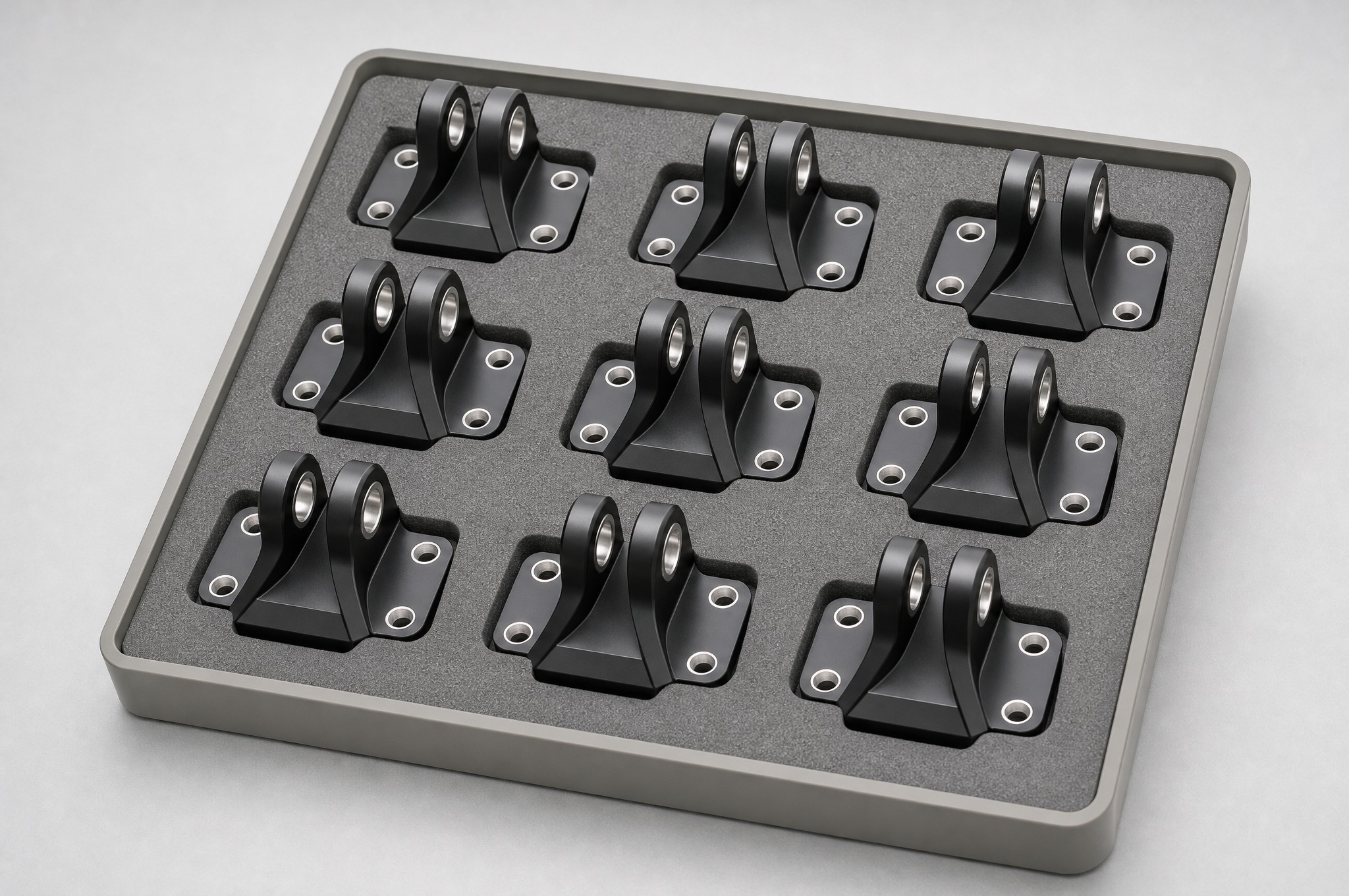
Multi-Sided 5-Axis CNC Machined Brackets
A bracket with holes on four faces is not four times harder to machine than a bracket with holes on one. It is harder in one specific way: every hole has to be right relative to a datum that exists on another face, and the moment the part comes off the fixture that relationship depends on the fixture having put it back in the same place. Everything on this page follows from that one sentence — the datum, the setup count, the angled pads, the ribs, the anodize allowance and the inspection report.
At a Glance
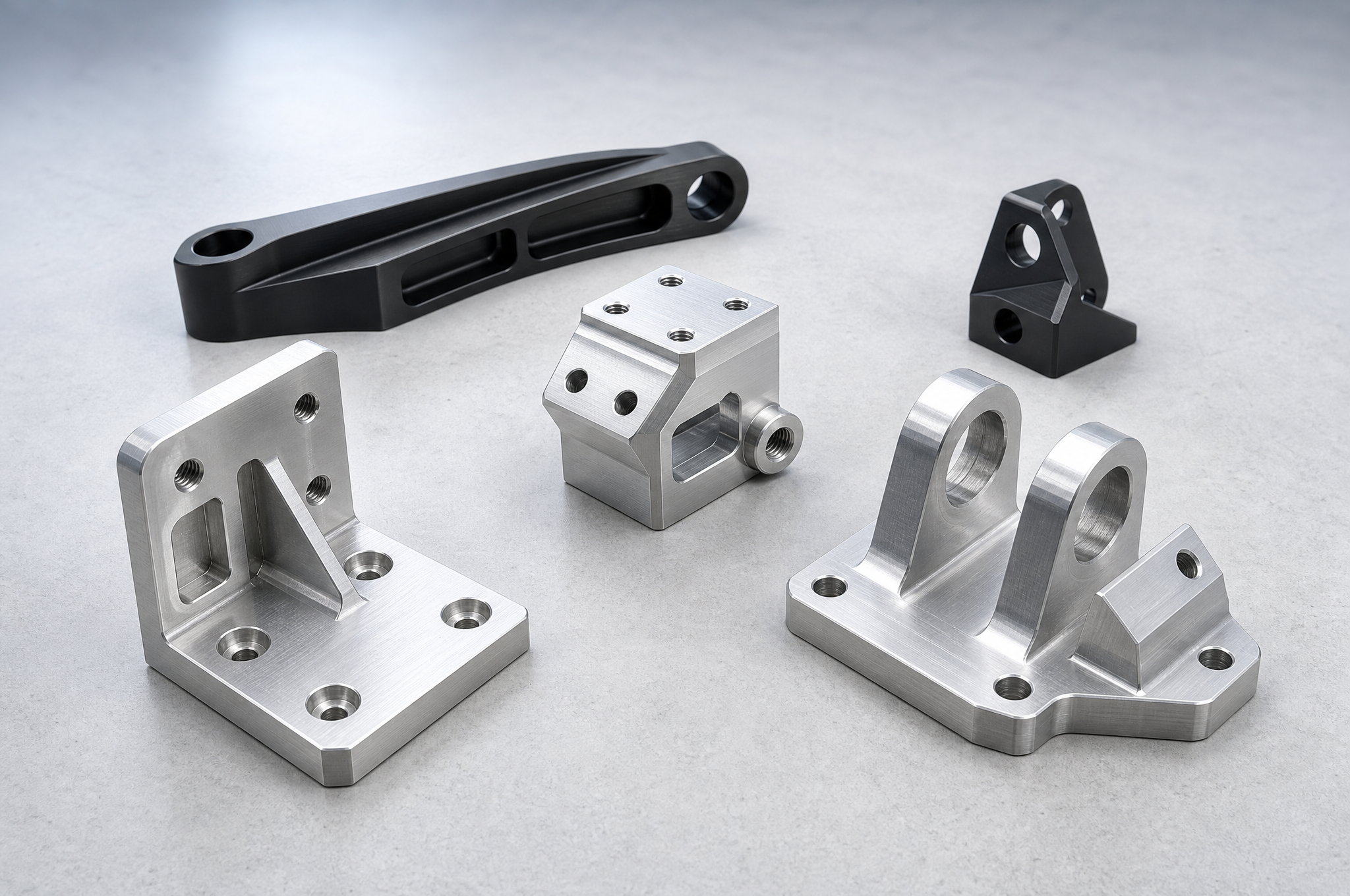
Multi-sided 5-axis CNC brackets are brackets whose mounting faces, hole patterns, angled pads and threaded bosses are distributed across several sides of the part, so that their positions are only meaningful relative to a common datum. Machining them well is less about reaching the faces than about not losing the datum between them: the faces that every hole is measured from are established once, as many features as possible are cut without releasing the part, and the remaining faces are indexed from the same datum rather than from the part's own outline. Goldcattle machines these brackets in 6061-T6 and 7075-T6 aluminum, with stainless, 17-4PH and Ti-6Al-4V where the application asks for them, on 3-axis, 3+2 indexed and simultaneous 5-axis equipment, and inspects cross-face position on a CMM using the drawing's datum reference frame. Not every multi-sided bracket needs simultaneous five axes: prismatic brackets with flat angled pads are usually better made on 3+2, and the page explains where the line falls.
Which Brackets Need Five Axes, and Which Do Not
Brackets arrive with very different amounts of geometry, and the first useful thing a machining quote can do is say which category the part is in. The categories below are not marketing tiers; each one implies a different fixture, a different number of setups and a different inspection plan.
| Bracket type | What the geometry looks like | Route that usually wins | Where the money goes |
|---|---|---|---|
| Single-face bracket | One mounting face, a flange, maybe a gusset; everything reachable from above | 3-axis, one or two setups | Material and finishing, not machining |
| Two-face bracket | An L or a U: a base plus one upstanding wall, holes in both | 3-axis with the second face indexed 90°, or 3+2 | The second setup and the squareness between the faces |
| Prismatic multi-face | Four to six flat faces at fixed angles, with holes, pads and bosses on several of them | 3+2 indexed, one or two setups | Fixture design and the datum plan |
| Curved or compound | Faces that change angle continuously: swept arms, blended transitions, sculpted ribs | Simultaneous 5-axis | CAM strategy and cutting time |
| Hybrid | A prismatic body with one or two curved transitions, or an angled pad that is also a curved surface | 3+2 for the flats, simultaneous for the curved band | Knowing where to switch, and not switching twice |
Most brackets we quote sit in the third row. That is worth saying plainly, because the phrase "five-axis bracket" suggests the fourth row and creates a mismatch between what a buyer expects to pay for and what the part actually needs. A prismatic bracket machined on 3+2 is not a compromise; on a flat face, an indexed position is usually more accurate and faster than a continuously interpolated one, because the machine locks and cuts instead of steering while it cuts.
What "Multi-Sided" Actually Means on a Drawing
Before the process, the census. A bracket is multi-sided in a way that matters if the features on different faces have to agree with each other. That is a property of the drawing, not of the shape, and it can be read off in a few minutes.
| Feature class | Why the face count matters | What has to be on the drawing |
|---|---|---|
| Mounting face | It is the surface that touches the neighbouring structure, so its flatness and its position set the assembly | Flatness, profile or position relative to the datum, and which face is the primary datum |
| Fastener holes | They are matched to a hole pattern that already exists on the mating part, so they are a copy of someone else's geometry | True position from the datum, hole size and tolerance class, and whether the pattern is dimensioned from an edge or from the datum |
| Counterbores and spotfaces | They set how far a fastener head sits below the surface, which is a clearance question, not a cosmetic one | Depth, diameter, and the surface they are measured from — which is not always the face they sit in |
| Threaded bosses | The thread is often the only feature that carries load repeatedly, and its axis is a direction as well as a position | Thread size and class, depth, and perpendicularity to the face it stands on |
| Angled pads | The angle is a functional direction; a pad that is 0.5° off moves a mating part by millimeters at the end of a lever | Angle with its own tolerance and the datum it is measured from, plus the pad's flatness |
| Bearing bores | Two bores on opposite ears are a single functional axis | Coaxiality or position of both bores to a common datum, and the fit class |
| Ribs and pockets | They decide stiffness and mass, and they change how the part deflects while it is being cut | Rib thickness and height, pocket floor thickness, and the radii that the tool can actually leave |
Count the faces that carry at least one of those features and you have the real scope of the job. A bracket with four faces of holes but only one functional pad is a single-face part with decoration; a bracket with two faces and a coaxial bore pair is a two-face part with a hard requirement. The count that matters is the count of dependent features — features whose correctness depends on another face — not the count of machined surfaces.
The Datum Is Chosen, Not Inherited
Every multi-face bracket has a datum whether the drawing names one or not, and if the drawing does not name one, the shop will pick the most convenient face and the inspector will pick a different one. That is how two competent people end up disagreeing about a part that is, in fact, correct.
A datum reference frame for a bracket is built in a fixed order, and the order is the whole point: three degrees of freedom first, then two, then one.
| Datum | What it constrains | How it is usually realised on a bracket | What goes wrong when it is chosen badly |
|---|---|---|---|
| A — primary | Three degrees: one translation, two rotations | The mounting face that touches the machine or the neighbouring structure, seated on three rest pads | Choosing a small pad as A makes every other face rock; choosing the "prettiest" face instead of the functional one moves the whole tolerance budget |
| B — secondary | Two degrees: one translation, one rotation | Two holes, one round and one diamond, or a long machined edge | A short face gives a weak angular reference, so the far end of the part swings; two round pins over-constrain the hole pitch |
| C — tertiary | One degree: the last translation | A single face or a single hole | Leaving C undefined lets the part slide along B, and the last hole is always the one that misses |
The hole pair as a secondary datum deserves its own note, because it is the most common mistake on bracket drawings. Two round locating pins in two round holes fixes four degrees, but the distance between the holes is not exact, so the part cannot seat: either it rocks between the pins or the second pin has to be relieved. The standard answer is one round pin and one diamond pin, so the pitch direction is free while the angular direction is fixed. If a drawing calls two round dowels, it is describing something that can only be assembled with clearance, which means the datum it defines is softer than it looks.
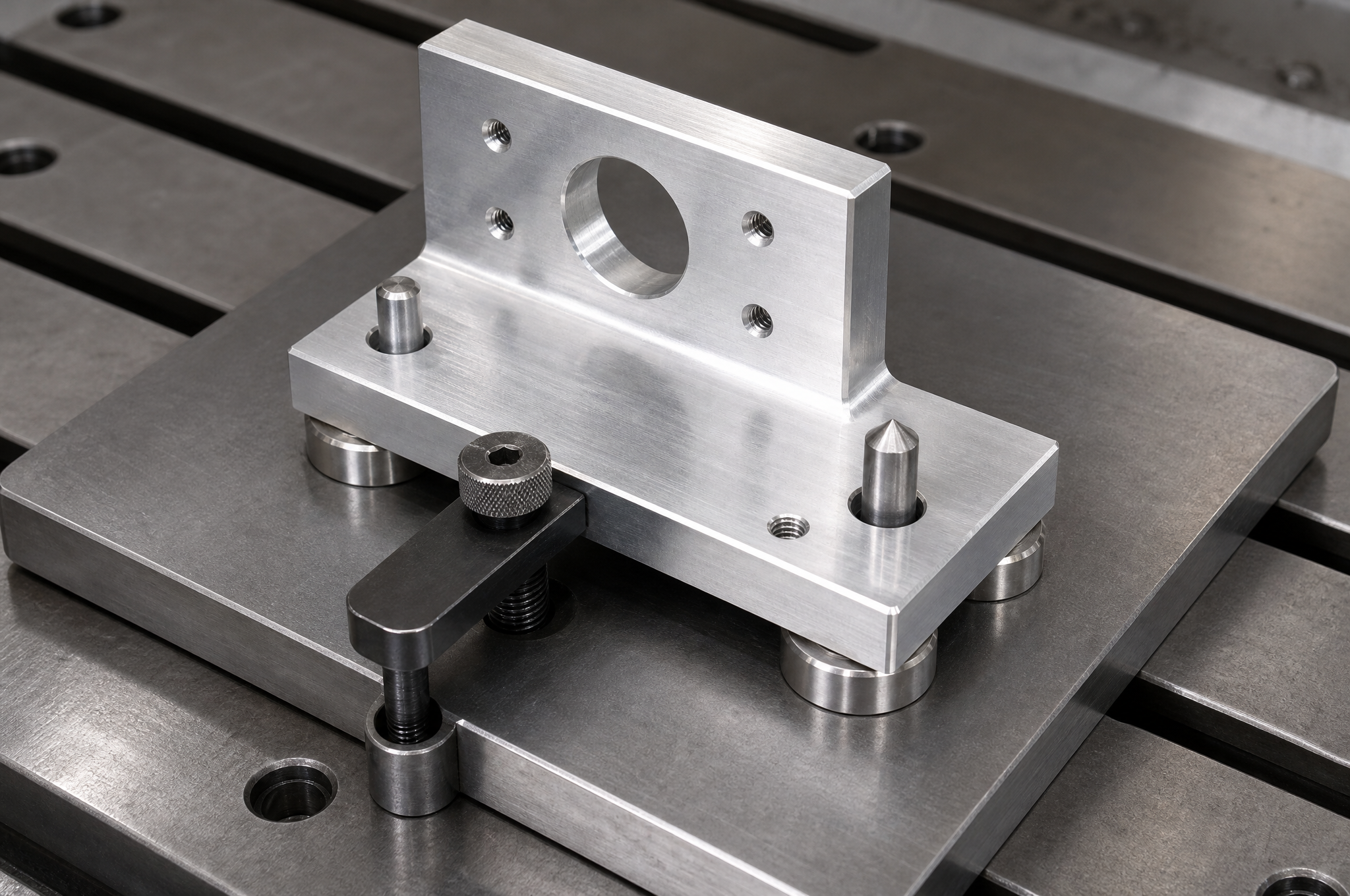
There is a second decision hidden inside the first. A datum can be a surface on the part, or it can be the fixture that holds it. Both are legitimate, and they are not interchangeable: the customer's inspection will use the part's face, so a report aligned to the fixture describes a different coordinate system from the one in the drawing. When the two disagree, the fixture was right and the report is answering a question nobody asked.
Cross-Face Position Is a Stack, Not a Number
A drawing that says "hole position ±0.05" is usually describing one hole in one setup. A bracket introduces a second question: what happens to that number when the hole is on face 3 and the datum is face 1, and the part has been off the machine in between.
The contributors are not exotic, which is exactly why they are ignored.
| Contributor | Order of magnitude | When it enters | How it is controlled |
|---|---|---|---|
| Machine positioning | A few micrometers over the working envelope | Every cut, in every setup | Ball-screw and scale condition; not something a drawing can influence |
| Index or rotary positioning | Tens of arc-seconds, which becomes micrometers at the part radius | Every 3+2 index | Index calibration; measuring across faces rather than trusting the readout |
| Fixture repeatability | 5–20 µm per re-clamp | Every time the part is released and re-seated | A dedicated fixture, not a vise; consistent clamp force |
| Clamping distortion | 10–50 µm on a thin bracket | While clamped, and again on release | Support under the clamp point; low-pressure clamping; light finishing pass |
| Thermal drift | 23 µm per meter per °C in aluminum | Across a long cycle or a warm afternoon | Stabilise the part; measure at a stated temperature, or at least at the same one |
| Probe and gauge uncertainty | 2–5 µm | At inspection, and at in-process probing | Calibrated probe, stated uncertainty on the report |
The thermal row is the one that surprises people, because the number looks small until it is multiplied by the part. Aluminum expands by roughly 23 µm per meter for every degree Celsius. On a 300 mm bracket, a 5 °C difference between the machine and the inspection room moves every feature by about 35 µm — half of a ±0.05 tolerance, spent before a single cut is made. This is why a bracket inspected straight off a warm machine can measure "out" and then be perfectly good the next morning, and why a report should say at what temperature it was produced.
Angled Faces: the Projected Dimension Trap
An angled pad looks like the simplest feature on a multi-sided bracket and is the one that most often produces a part that measures right and does not fit. The reason is not the angle; it is what the dimension on the drawing actually refers to.
A hole on a pad inclined at 30° can be located in two different ways, and they differ by about 15%.
| What the drawing shows | What it means | Consequence |
|---|---|---|
| A dimension taken in the front view, parallel to the base | The projected distance: the hole's position as seen from the front | On a 30° pad, 20 mm projected is 23.1 mm measured along the pad. If the shop reads it as a true distance, the hole lands 3 mm low. |
| A dimension taken along the inclined face | The true distance from the pad edge or from a datum feature on the pad | Unambiguous, but only if the datum on the pad is itself defined — usually the intersection line of the pad and the neighbouring face |
| A basic dimension with a position tolerance to A|B|C | The true position in the datum frame, with no chain | The cleanest option: the inspector does not have to reconstruct an angle to know where the hole should be |
The angle itself needs the same treatment. A tolerance of ±0.5° sounds tight until it is multiplied by a lever: on a pad 100 mm from the datum, half a degree is 0.87 mm of movement at the far end. That is the number the mating part will see, so the tolerance should be chosen from the assembly, not from the convenience of the angle block.
There is a machining consequence as well. A hole that must be normal to a 30° pad cannot be drilled properly on a 3-axis machine with the part sitting flat: the drill enters at an angle, starts as an ellipse, walks across the surface, and leaves an asymmetric burr on the high side. Tilting the part — which is what 3+2 is for — makes the hole round, the depth true to the drawing, and the entry edge clean. On a bracket with six angled holes, that difference alone can decide the route.
What One Clamp Actually Buys
Setup count is the single most useful number on a bracket quote, because it drives cost and accuracy in the same direction. More setups means more fixture time and more accumulated datum error, and the second effect is the one that shows up in assembly rather than in a report.
| Setup strategy | Faces reached | What it costs | What it risks |
|---|---|---|---|
| One setup, 3-axis | The top face and anything visible from it | Lowest: one fixture, one program | Every other face needs a second operation, and the second operation inherits the first one's datum |
| Two setups, 3-axis | Top and one side, or top and bottom | One more fixture or a re-fixture, plus alignment time | The relationship between the two faces is only as good as the re-fixture, and it is never re-checked in the same way |
| One setup, 3+2 | Four or five faces, one of them held | One fixture and one program, but a slower CAM job and a machine with two rotary axes | The held face cannot be machined in that setup; if it carries the primary datum, it must be finished in a later operation |
| One setup, simultaneous 5-axis | Continuous surfaces plus the reachable flats | Highest CAM and cutting time | Interpolation error across the surface; less rigidity at the extremes of the rotary axes |
| Two setups with a matched fixture | All six faces, by flipping the part in a designed pair of fixtures | A second fixture, designed together with the first | Only as good as the fixture pair's relationship — which is exactly why they should be machined together |
The phrase to be careful with is "one setup". A bracket can only be machined in one setup if there is a face left to hold, and that face is usually the one the fixture sits on. On a part with critical features on all six faces there is no such thing as a single setup; there is a designed pair of setups, and the honest engineering question is which pair leaves the least important face to last.
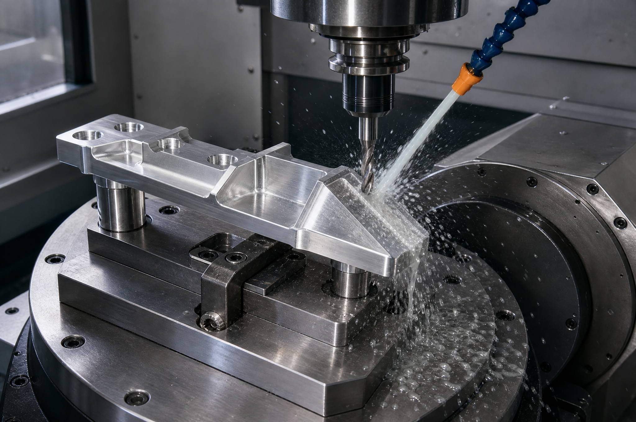
There is also a hardware limit that drawings rarely acknowledge. The machine's travels are not the machinable envelope of a five-axis part: the fixture sits between the table and the part, the rotary axes have to swing the part without hitting the enclosure, and the tool holder needs clearance from the workpiece at every angle. A 400 mm bracket on a trunnion may need a machine with 600 mm of travel to cut it, and a feature near the corner may be unreachable at the angle the geometry requires. If a bracket is close to the machine's capacity, the right time to find out is at quotation, by drawing the setup, not at the first article.
What In-Process Probing Can and Cannot Fix
Probing is often presented as the thing that makes multi-face work accurate. It is useful, and it is narrower than it sounds: a probe measures where the part is, and then the control shifts the coordinate system to match. What it cannot do is change the shape of the part, the stiffness of the fixture, or what happens after the probe retracts.
| Situation | Can probing help? | Why |
|---|---|---|
| The blank sits a little off in the fixture | Yes | The probed features define where the part actually is, so the program can be shifted to suit |
| The blank is a sawn plate with 0.3 mm of variation in thickness | Partly | Probing finds the top face, but the stock left on the side walls is still uneven, so the first pass has to be conservative |
| The fixture deflects when the clamp is tightened | No | The probe measures the clamped state; if the fixture moves again under cutting force, the datum has already been taken |
| The part warms up during a long cycle | No | The shift is applied once, at the start; thermal growth after that is invisible to the control |
| The tool deflects in a deep pocket | No | Probing measures the part, not the cut; the error appears in the walls after the tool has passed |
| The part springs when the clamps are released | No — and this is the dangerous case | The in-process measurement is taken while clamped; the customer measures it free |
Two habits make probing worth its cycle time. The first is to probe a machined face rather than a raw one: a sawn or cast surface is rough enough that the probe's single point describes a texture, not a location. The second is to record the shift. A probe result that lives only in the control offsets is invisible in the quality record, and a datum shift of 0.04 mm on a part with a ±0.05 cross-face position is worth knowing about — if only because it tells you the fixture is drifting before the parts start failing.
3-Axis, 3+2, or Simultaneous 5-Axis
The three routes use the same machine tools in many shops and produce different economics. The table below is the decision we apply at review, stated as what each route is good at rather than as a hierarchy.
| Route | Degrees used | Best bracket geometry | Accuracy character | Where it is weak |
|---|---|---|---|---|
| 3-axis | Three linear | Plate-like brackets, one dominant face, pockets and ribs on that face | The best accuracy per face, because the machine never re-orients | Anything on a side face needs a new setup |
| 4-axis | Three linear plus one rotation | Brackets with features distributed around a bore or a shaft axis | Good angular consistency around the axis | Faces not normal to the rotation still need a second operation |
| 3+2 indexed | Two rotary axes, locked | Prismatic multi-face brackets: flat pads, angled faces, cross-face hole patterns | Positional accuracy set by the index and the machine, with the tool cutting in a rigid locked position | Cannot follow a continuously changing surface; index moves cost time |
| Simultaneous 5-axis | Five interpolated | Swept arms, blended transitions, sculpted ribs, compound curvature | Tool stays normal to the surface, so the profile is continuous and the scallop is controlled | Slower feed, more CAM engineering, and the least rigid configuration at the extremes of travel |
A 5-axis machine does not make five-axis work. Most brackets cut on a five-axis machine are cut in a 3+2 sequence, and that is the correct use of the machine: the rotary axes exist to present faces, not to decorate the tool path. The distinction matters commercially, because a buyer who asks for "five-axis" for a prismatic part is often asking for a slower, more expensive process than the part needs, and a supplier who agrees without saying so is selling the word rather than the result.
Ribs, Pockets, and Where the Stiffness Went
Lightening a bracket is not the same as removing material. Two parts can lose the same mass and end up with different stiffness, because what matters is where the material was.
| Change | Effect on mass | Effect on bending stiffness | Practical note |
|---|---|---|---|
| Pocket the web between ribs | Large reduction | Small, if the outer flange keeps its thickness | Material near the neutral axis carries little bending load; this is the cheapest weight to remove |
| Thin the outer flange | Moderate reduction | Large loss — stiffness falls roughly with the cube of thickness | The flange is the farthest material from the neutral axis; thinning it is the most expensive weight to remove |
| Add a rib | Small increase | Large gain, and it grows faster with rib height than with rib width | Ribs should run across the bending direction, not along it |
| Increase rib height, keep width | Small increase | The most efficient stiffness per gram available | Limited by buckle and by how tall a thin fin can be machined without chatter |
| Replace a solid corner with a gusset | Reduction | Depends entirely on the gusset's depth | A shallow gusset is decoration; depth along the load path is what works |
The manufacturing side of that table is the fin problem. A rib 1.5 mm wide and 12 mm tall has an aspect ratio of eight, and while it is being cut it is a spring: the tool pushes it, it deflects, the finished wall is thin in the middle and the surface carries chatter. The usual answers are to taper the rib — full width at the base, two-thirds at the crest — to rough it from both sides so the load is balanced, and to take the finishing pass with the tool cutting downwards along the rib rather than across it. All three are geometry-visible on the drawing, which is why they belong in a DFM review rather than in a machining complaint.
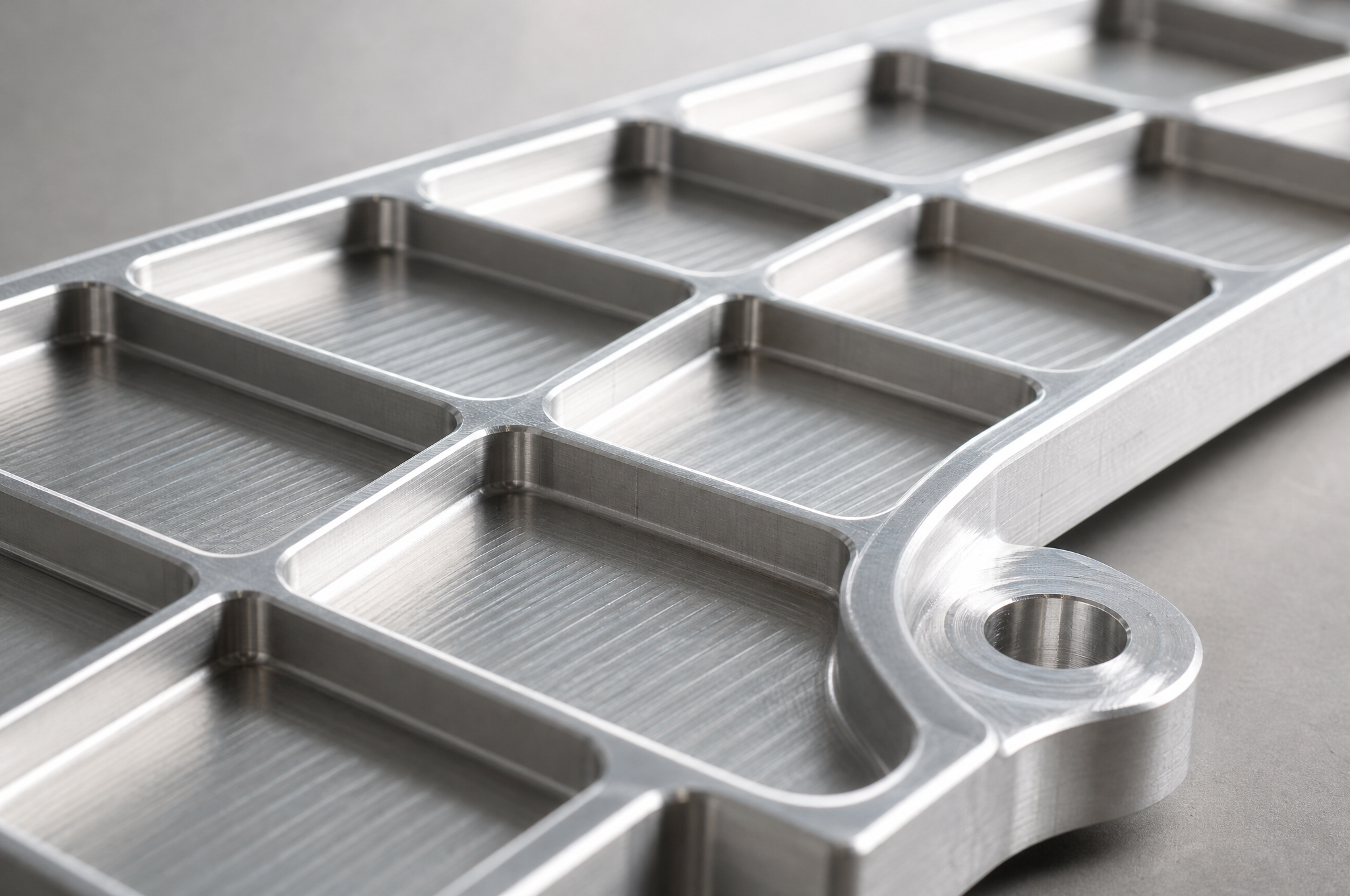
The pocket floor has its own rule. A floor thinner than about 1.5 mm under a 6 mm cutter will deflect while it is being cut and will not come out flat, and the error is worst in the middle of the pocket, where nobody measures. If the design needs a thin floor, it needs either a smaller cutter, a supported setup, or a tolerance that admits the deflection. The same applies to a wall that is thin in the middle and thicker at the edges: the finished part will be thinner than the drawing everywhere the tool could push.
Thin Walls, Clamping, and the Free-State Part
A bracket is measured on a bench, not in a vise, and the difference between those two states is the most common reason a part that was "in tolerance on the machine" is rejected at goods-in.
Aluminum is compliant enough that a 1.5 mm wall will follow the clamp. The cut is then made to a shape that includes the deflection, and when the clamp is released the wall springs back to something else. On a pocket 80 mm long, the spring can be tens of micrometers — more than the tolerance on the wall position, and invisible to any measurement taken before release.
| Symptom on the bench | What happened | What prevents it |
|---|---|---|
| Wall position out, wall thickness fine | The wall was pushed over while clamped and came back | Support behind the wall; lower clamp force; finish after the bulk is removed |
| Wall thickness varies along its length | The wall deflected differently depending on how much material remained | Rough and finish separated, with a consistent allowance and a light final pass |
| Bracket bows after the last operation | Residual stress in the plate, released as the section was removed | Stress-relieved stock: T651 plate is stretched after heat treatment for exactly this reason, where T6 is not |
| Holes drift after the pockets are cut | The pockets changed the stiffness, and the part relaxed around the holes | Cut the pockets before the final hole operation, or leave the holes for a finishing pass |
| Part is flat on the machine and not on the bench | It was measured while still clamped to a flat surface | Measure free-state; if the drawing means clamped, it has to say so |
The stock specification is the part of this that buyers control most cheaply. Plate that has been stress-relieved by stretching — the T651 condition in 6061 and 7075 — is dimensionally more stable after heavy pocketing than the same alloy in T6, and on a bracket with most of its web removed the difference is visible in the flatness after machining. That is a one-word change on a purchase order and it is worth more than a tighter tolerance on the finished part.
6061 or 7075, and When Neither Is Right
Almost every multi-sided bracket we quote is 6061-T6 or 7075-T6, and the choice between them is usually made on strength. That is the right first question and the wrong only question, because the two alloys behave differently on the machine and after it.
| Property | 6061-T6 / T651 | 7075-T6 / T651 |
|---|---|---|
| Tensile strength, typical handbook values | Around 310 MPa | Around 570 MPa |
| Machinability | Good; forgiving of small changes in speed and feed | Good to excellent, but the window is narrower and heat at the edge matters more |
| Corrosion resistance | Good, with or without finishing | Noticeably lower; the copper that gives the strength also gives it up at a scratch or a cut edge |
| Response to anodizing | Uniform color, predictable growth | Color can vary with heat-treat condition; hard anodizing is known to reduce fatigue strength, which is a structural decision rather than a cosmetic one |
| Welding | Weldable | Not recommended; welded 7075 loses the property it was chosen for |
| Typical bracket role | Equipment mounts, sensor brackets, robotics fixtures, general structural parts | Aerospace and UAV structure, high-load robot links, parts where every gram is argued about |
| Cost | Lower material cost and a wider supply of plate | Higher material cost, and a narrower range of thicknesses in stress-relieved plate |
The mistake to avoid is treating 7075 as the better version of 6061. It is stronger and less forgiving: it is more notch-sensitive, so a sharp internal corner in a 7075 bracket is a worse idea than the same corner in 6061; it corrodes more readily at an exposed edge, so an unfinished 7075 part outdoors is a maintenance item; and if the design needs welding, 7075 stops being an option rather than becoming a difficult one. Where the load path genuinely needs the strength, 7075 is the right answer and the finishing spec becomes part of the structural design.
| Material | Why it appears on a bracket drawing | What to check before quoting |
|---|---|---|
| 5052 aluminum | Formable sheet brackets, covers, parts made by bending rather than milling | If the part is essentially a formed panel, the route is sheet metal, not five-axis milling — and it will be cheaper |
| 304 / 316 stainless | Corrosion resistance, washdown environments, visible hardware | Work hardening and roughly three times the density; a stainless bracket of the same stiffness is heavier, not just slower to cut |
| 17-4PH | High strength in a small section, with a hardness that can be raised by aging | The condition and the aging step decide finished dimensions; the allowance has to be agreed before the first cut |
| Ti-6Al-4V | Strength-to-weight where aluminum is not enough and weight still matters | Low thermal conductivity concentrates heat at the edge; tool life and burr removal are the real cost, not the metal |
Anodizing Moves the Fit
Anodizing is not a coating sitting on the surface. It converts aluminum into an oxide layer that grows out of the metal and, depending on the process, into it as well — which means it changes the size of everything it touches. On a bracket, that includes the bores, the threads and the pads that are supposed to sit flat against something else.
| Process | Typical thickness per surface | Dimensional effect | Where it belongs on a bracket |
|---|---|---|---|
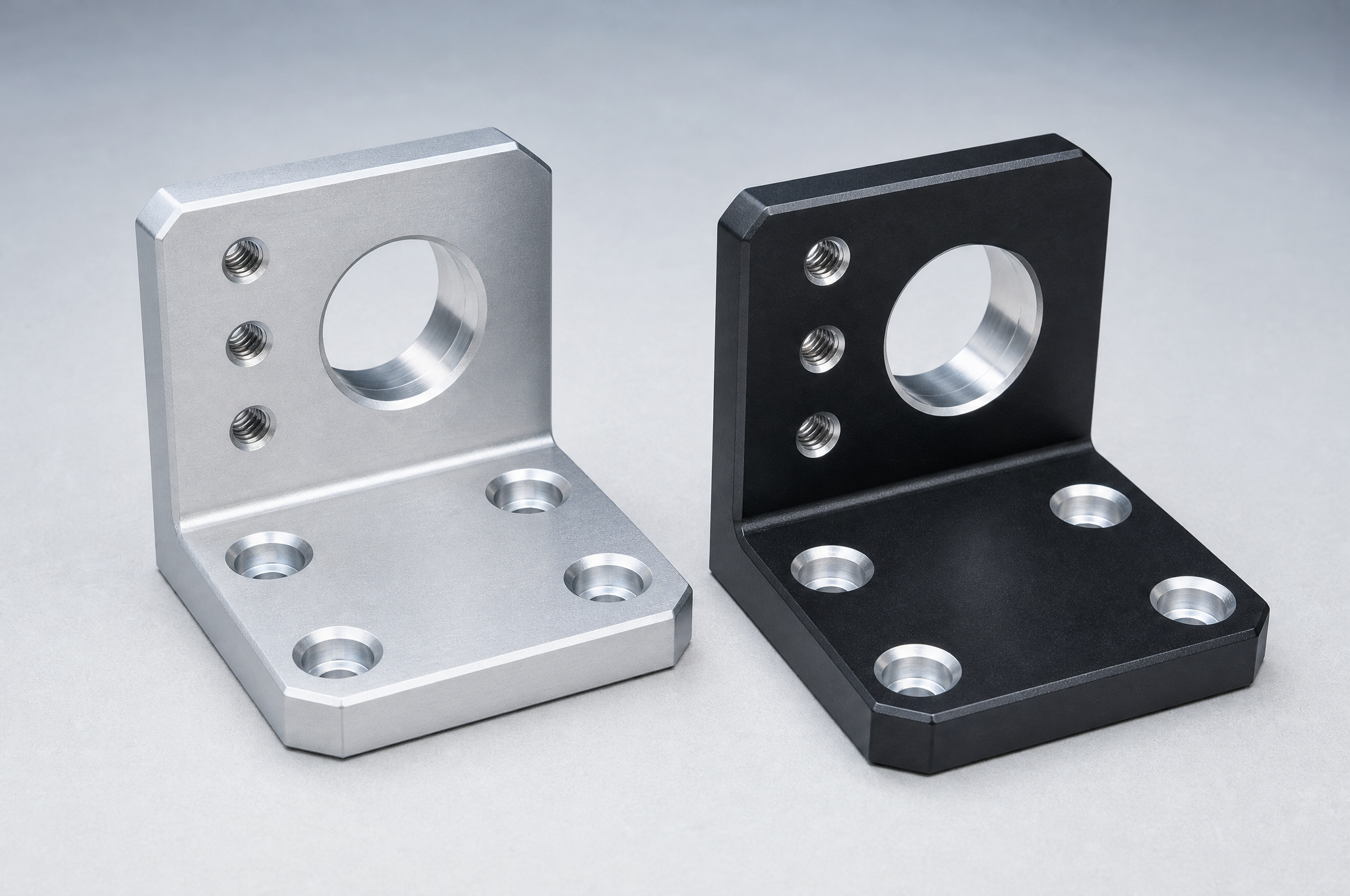
| Clear or black anodize, Type II | Roughly 10–25 µm | A bore closes by about twice the coating thickness across its diameter; a thread tightens | General protection and appearance; the usual choice for equipment and robotics brackets |
| Hard anodize, Type III | Roughly 25–50 µm | Doubles the effect of Type II, and the layer is brittle in comparison | Wear surfaces and sliding interfaces; not automatically the right choice on a part that flexes |
| Chromate conversion coating | Well under a micrometer | Effectively no dimensional change | Where electrical bonding or grounding has to survive, because the film conducts |
| Masking | — | Keeps a feature at nominal size by keeping the coating off it | Bearing bores, dowel holes, grounding pads and any thread that will be assembled after finishing |
Two decisions follow, and both have to be made on the drawing. The first is whether a bore is dimensioned before or after coating: a 10 mm bore that is reamed to size and then anodized is no longer a 10 mm bore, and if the mating part is a bearing or a dowel, the fit has moved by the whole of the coating. The usual answers are to mask the bore, to leave the machining undersize by the coating allowance, or to finish the bore after coating — and each of those is a line in the process route with a cost attached.
The second is threads. An anodized thread is tighter, sometimes to the point where a fastener will not start without damaging the film. Masking the thread, chasing it after coating, or specifying a slightly different class are all normal, but the choice has to be made before the parts are coated, because after that the only options are rework and rejection.
Whose Datum Is the CMM Using?
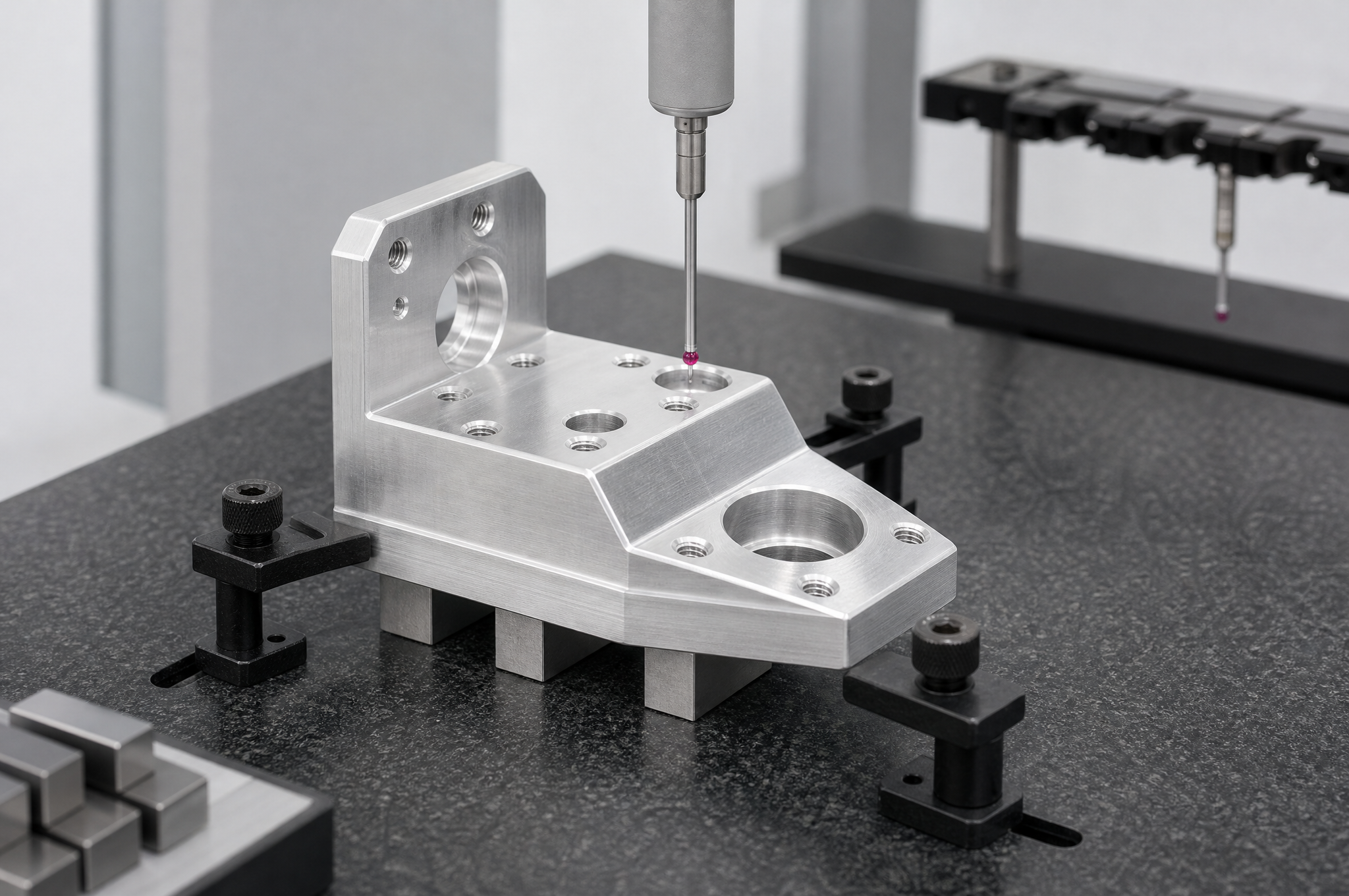
A cross-face position report is only meaningful if it says what it was measured from. Two inspectors can measure the same bracket on the same machine and report different numbers, both correctly, because they aligned the part differently. That is not a metrology failure; it is a specification gap.
The datum reference frame on the drawing defines an order: primary plane, secondary, tertiary. The CMM has to reproduce that order, using the features the drawing names, and the report has to say so. On a bracket this usually means:
| Step | What is measured | What it fixes | Common error |
|---|---|---|---|
| Align A | A plane on the mounting face, from enough points to establish flatness as well as position | Three degrees of freedom | Using the largest face rather than the drawing's primary datum |
| Align B | Two holes, or a machined edge long enough to be angularly stable | Two degrees | Using two short hole segments, which gives a noisy axis |
| Align C | The tertiary face or hole | The last translation | Leaving C out of the alignment and then reporting a position that floats |
| Measure | Each cross-face hole as a cylinder, with enough points to see form | The reported position | A three-point circle on a bore with form error, which biases the center |
Two conventions cause most of the arguments. The first is the shape of the tolerance zone. A position tolerance of Ø0.1 describes a cylindrical zone 0.1 mm in diameter; a bilateral tolerance of ±0.05 in X and Y describes a square 0.1 mm on a side. They are not the same requirement: the square's corners lie outside the circle, and the circle's edge lies outside the square on the axes. If a drawing mixes the two — a true position callout with coordinate-style tolerances elsewhere — the inspector has to pick one interpretation and the shop has to be told which.
The second is the maximum material condition. If a position callout carries the MMC symbol, the tolerance grows as the hole grows: a hole made at its upper limit earns a bonus equal to the difference. That bonus is real and it is often left on the table because the drawing did not say MMC, or because the report quotes the base tolerance and never mentions the bonus. On a bracket with a hole pattern that is hard to hold, the difference between an RFS and an MMC callout can be the difference between a rejected batch and an accepted one — and it is a drafting decision, not a machining one.
Capability Matrix: Structure to Route to Inspection
This is the table we build during a bracket review, and it is the shortest way to explain why two brackets that look similar are quoted differently.
| Structure | Route | What decides the route | What has to be inspected |
|---|---|---|---|
| Mounting face plus one wall | 3-axis, two setups | How the second face is located after the flip | Flatness of both faces; perpendicularity between them; hole position from the face that touches the structure |
| Four-face block with cross-face holes | 3+2, one or two setups | Which face can be held, and whether the datum face can be finished in the same setup | True position of every cross-face hole from A|B|C; perpendicularity of the faces |
| Angled pad with a hole normal to it | 3+2, pad presented square | Whether the angle can be reached without the holder fouling | Pad angle, pad flatness, hole position in the pad's own frame |
| Two ears with coaxial bores | 3-axis or 3+2 with line boring | Whether both bores can be cut from one side | Coaxiality or position of both bores; fit size; burr at the breakout |
| Thin-wall pockets and ribs | 3-axis, rough and finish separated | Wall thickness and how much support the fixture can give | Wall thickness, floor thickness, flatness in the free state |
| Swept or blended structure | Simultaneous 5-axis | Whether the surface changes angle continuously | Profile against the model; surface finish on the visible faces |
| Threaded bosses on several faces | Whichever route reaches them | Access for the tap or the thread mill, and the depth | Thread size and class, perpendicularity to the seating face, position |
A Checklist for the Drawing, Not for the Supplier
These ten items decide whether a multi-sided bracket is straightforward or expensive. They are written for the person who owns the drawing, because every one of them is cheaper to change before release than after the fixture is made.
| # | Check | Why it is on the list |
|---|---|---|
| 1 | The primary datum is the face that actually touches the neighbouring structure | If it is not, every other tolerance is being measured from the wrong place |
| 2 | Secondary and tertiary datums are named, and the secondary is wide enough to be angularly stable | An unnamed datum gets chosen twice — once by the shop and once by the inspector |
| 3 | Cross-face hole positions are basic dimensions with a position tolerance to the datum frame | Chain dimensions from different edges accumulate; position tolerances do not |
| 4 | Flatness and perpendicularity are assigned to the surfaces that seat, not to every surface | Tolerancing a non-functional face adds inspection time and buys nothing |
| 5 | Internal corner radii are larger than the cutter that has to reach them | A 0.5 mm corner 8 mm deep needs a tool that cannot survive the depth |
| 6 | Wall and rib thicknesses are stated, with the minimum called out | Thin sections are where clamping deflection and chatter appear |
| 7 | Tool and holder access is checked at every angle the part will be presented at | A feature can be geometrically reachable and physically blocked by the holder |
| 8 | Anodize type and masking are specified, and the effect on bores and threads is allowed for | Coating closes a bore; the allowance belongs on the drawing, not in a conversation |
| 9 | The critical interfaces are listed, so they can be the ones reported | A report with five meaningful characteristics beats one with forty |
| 10 | It says whether tolerances apply free or clamped, and at what temperature | Aluminum moves 23 µm per meter per °C; a 5 °C difference is 35 µm on a 300 mm part |
Item 10 is the one that is almost always missing and almost always matters. A bracket that is inspected clamped to a surface plate is being measured in a state the customer will never assemble it in, and a bracket measured at 30 °C in a workshop and installed at 20 °C in a laboratory is a different size. Neither of those is a defect; both are reasons for a disagreement that costs a week.
Cost, Lead Time, and What Repeatability Actually Requires
A multi-sided bracket is expensive for three reasons, and only one of them is the metal.
| Driver | Why it costs | What can be moved without losing the function |
|---|---|---|
| Fixture design | A multi-face part needs a fixture that locates it repeatably, not a vise that holds it | Standardise the datum features across a product family so one fixture serves several part numbers |
| Setups | Every re-clamp is alignment time, program time and a datum to re-establish | Consolidate features onto faces already being cut; move a non-functional hole to a reachable face |
| Small tools in deep pockets | A 3 mm cutter in a 25 mm deep pocket runs at reduced feed and still deflects | Open the pocket, increase the corner radius, or reduce the depth |
| Over-toleranced holes | A ±0.02 position on a clearance hole is inspection time with no assembly benefit | Leave general tolerances on clearance holes; reserve position tolerances for locating features |
| Wall and rib geometry | Thin sections force light passes and slow feeds to avoid chatter | Taper the rib, thicken the root, or accept a slightly heavier part |
| Masking | Every masked bore or thread is hand work before and inspection after | Reduce the number of masked features; finish a bore after coating instead of masking it |
| Inspection | A CMM program is per part number, and cross-face position takes longer than a single face | Agree the characteristic list; report the five that matter |
Lead time follows the same list rather than the quantity. A first article is dominated by fixture design, programming and the first inspection; a repeat order on the same revision is a fraction of that. When a quote shows a large gap between the first and the repeat price, the gap is engineering, and it is worth asking what would have to be frozen to bring the second number forward.
Repeatability is the part of the promise that a sample cannot demonstrate. A bracket that is right once proves the machine can make it; a bracket that is right on the four hundredth part proves the process was designed. On a multi-face part that means the fixture does not wear into a different position, the program is tied to a drawing revision, and the datum is checked at intervals rather than only at first article.
What to Send for a Bracket Quote
A bracket enquiry that carries the datum, the mating parts and the finish will usually be quoted without a second round of questions. The list below is the one that changes either the price or the part.
| Item | What it should contain |
|---|---|
| Model and drawing | STEP, IGES, X_T, DXF or a dimensioned PDF, at a named revision, with the drawing and the model agreeing |
| Function of the bracket | What it carries, what it bolts to, and which face seats against the structure |
| Datum scheme | A, B and C as the drawing defines them, or a note that the scheme is still open |
| Material and condition | Alloy and temper, for example 6061-T651 or 7075-T651 plate; whether stress-relieved stock is required |
| Critical characteristics | The cross-face positions, flatness and perpendicularity that decide assembly, with tolerances |
| Finish | Anodize type and color, masking requirements, and whether bores or threads are finished after coating |
| Quantity | Prototype, pilot and annual volume stated separately, with the expected number of revisions |
| Evidence | Material certificate, dimensional report, CMM report, FAI, and the characteristics each should cover |
| Assembly context | The mating part or its interface dimensions, if the bracket is a copy of an existing design |
| Temperature and state | Whether the drawing's tolerances apply at 20 °C, and whether they apply clamped or free |
If the drawing is not final, send what exists and say which characteristics are still moving. An assumption written into a quote can be argued with; an assumption buried in a machining program cannot.
Frequently Asked Questions
What are multi-sided 5-axis CNC brackets?
When should I use 3+2 machining instead of simultaneous 5-axis?
Can 5-axis CNC machining produce brackets with holes on five faces?
How do you keep hole positions consistent across multiple mounting faces?
Which aluminum alloy is better for a precision mounting bracket, 6061 or 7075?
Can you machine lightweight 7075-T6 aerospace brackets?
How do you control thin-wall deformation in aluminum brackets?
Can CNC machined brackets be hard anodized?
How do you inspect the flatness and perpendicularity of a CNC bracket?
What CAD and GD&T information should I send for a bracket quote?
Do you quote from a sample instead of a drawing?
What information changes the price most on a multi-face bracket?
Send the Bracket, the Datum and the Mating Part
Share the 2D drawing or 3D model at a named revision, the face that seats against the structure, the material and temper, the cross-face positions that decide assembly, and the finish with the surfaces that must stay bare. The review covers the datum scheme, the fixture, how many faces can be cut without releasing the part, and where the anodize allowance will change a fit — and anything that cannot be reached or measured as drawn is raised before the quotation rather than at first article.
Request a Bracket QuoteSTEP, IGES, X_T, DXF, DWG or PDF · prototype, pilot batch and repeat production
See the wider aluminum bracket scope →Related Capability and Reading
Process
5-axis CNC machining services — machine configuration, axis arrangement and what each is used for.
Material
7075 aluminum 5-axis machining — the alloy in practice, including the published structural bracket project.
Industry
Aerospace CNC parts — the wider aerospace scope, including structural and avionics hardware.
Finishing
CNC surface finishing — anodizing, passivation and the dimensional effect of each.
Quality
Quality and certifications — what our quality system covers and what it does not.
Parent page
Custom CNC aluminum brackets — materials, industries and the published robotics and ECU bracket projects.