Custom CNC-Machined Pump Components Made to Your Drawings
A pump part is not judged on its own dimensions. It is judged on the clearance it leaves when it is assembled with two or three other parts: the gap between the impeller and the wear ring, the fit of the shaft in the bearing bore, the runout the seal sees at the sleeve. Those are relationships spread across separate drawings, held by separate tolerances, and they only add up correctly if the parts were made with the assembly in mind. That is the subject of this page — which features carry the running behaviour, how they are controlled, and what evidence comes with them. We machine the components; the pump's hydraulic design, balancing and pressure testing belong to the pump builder.
At a Glance
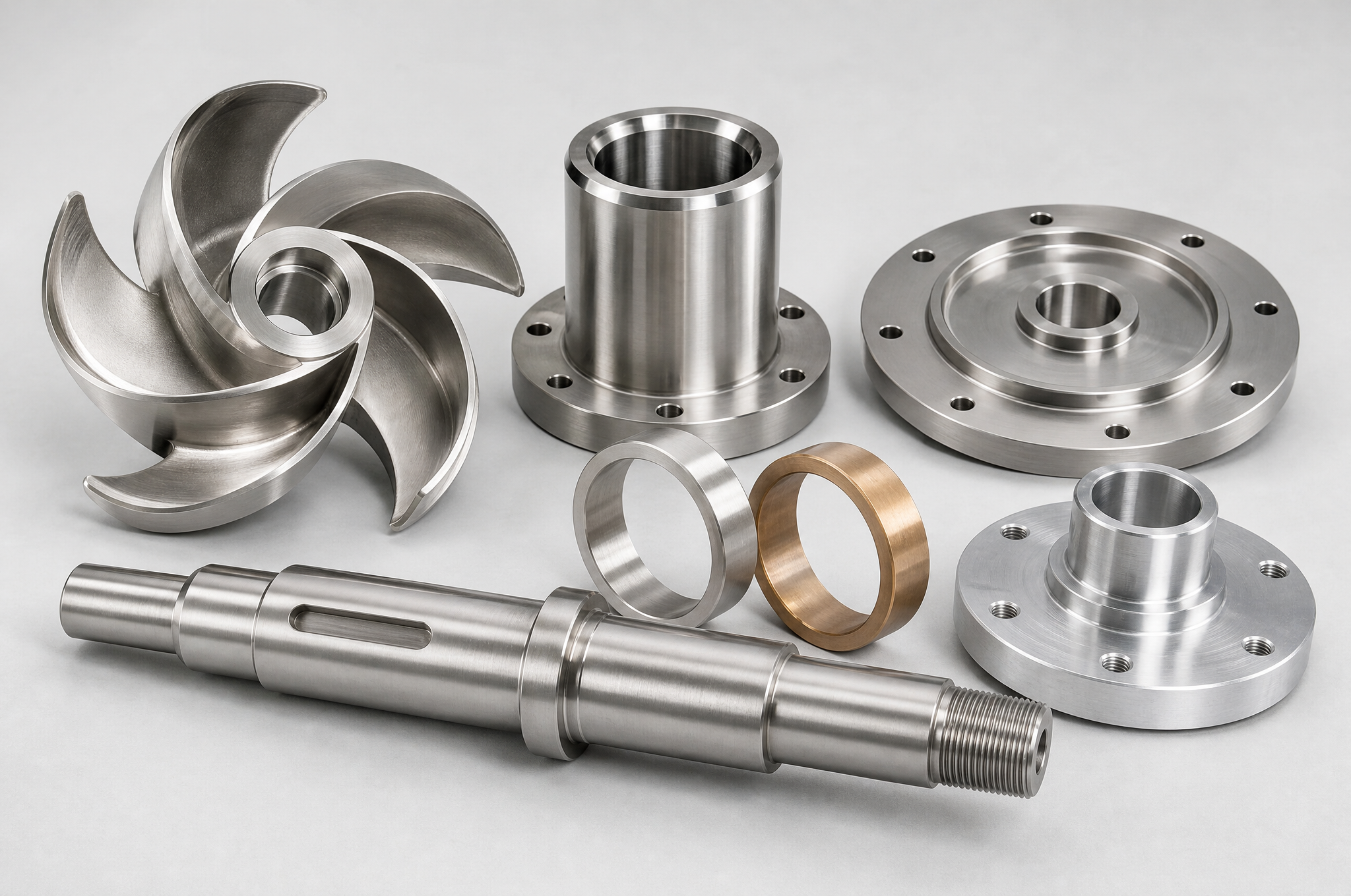
What you are buying is not five parts; it is a set of clearances that add up. A pump that runs quietly and seals properly does so because the gap between the impeller and the wear ring is right, the shaft sits in its bearing bore with the correct fit, and the seal sees a shaft surface that runs true. Each of those is a relationship between two parts, and a relationship cannot be inspected on either part alone. So three things follow for anyone quoting a pump component drawing. The critical dimensions are the mating ones — bore diameter and roundness, journal size, runout, seal-face flatness, groove depth — not the outside profile. The material has to be chosen against the medium and the temperature, not against a grade name, because 316L is the wrong answer for some chlorides and bronze is the wrong answer for some seawater. And the drawing has to state which fit applies, because a nominally correct bore and a nominally correct shaft can still be a loose or an interference assembly depending on which side of tolerance each landed. We machine to those relationships and report on them; the pump's hydraulic design, balancing and pressure test stay with the pump builder.
What This Page Covers, and What It Hands Back
Goldcattle already publishes a page on pump mechanical seal components, and a page on general CNC machining. This page sits between them, and it is worth saying at the start what each one is for, because a buyer who lands on the wrong one wastes a week.
| Page | What it answers | What belongs there rather than here |
|---|---|---|
| This page: custom CNC pump components | Which pump parts we machine, how the running features are controlled, what the material and inspection evidence looks like | The component families, the critical features, the clearance logic, matched-part manufacturing, replacement from samples |
| Pump mechanical seal parts | Seal-specific components: seats, glands, sleeves, holders, seal housings | Seal-part taxonomy, wear and failure diagnosis, seal material comparison, legacy seal reproduction |
| CNC machining services | The plant, the equipment, the published tolerance and size tables | Machine list, envelope, general capability, floor photography |
| Die casting services | Aluminum, zinc and magnesium castings with CNC finishing | Housings whose route is a casting plus machining, which is a volume decision rather than a machining one |
Two boundaries are worth stating plainly, because they decide whether an enquiry is even the right shape. A machined housing is not a casting route. A pump housing can be cut from solid when the annual volume is low, the wall geometry is simple, or the material is not castable in the required grade; at volume, a casting with machined interfaces is usually the cheaper route, and that decision belongs to a casting review rather than to a machining quotation. And a machined component is not a pump. We do not design the hydraulic passage, set the running clearance, balance a rotating assembly or pressure-test a casing. Where a drawing calls for those, they are the pump builder's scope; what we control is the geometry and the evidence behind it.
The Rotating Group Is the Real Unit of Purchase
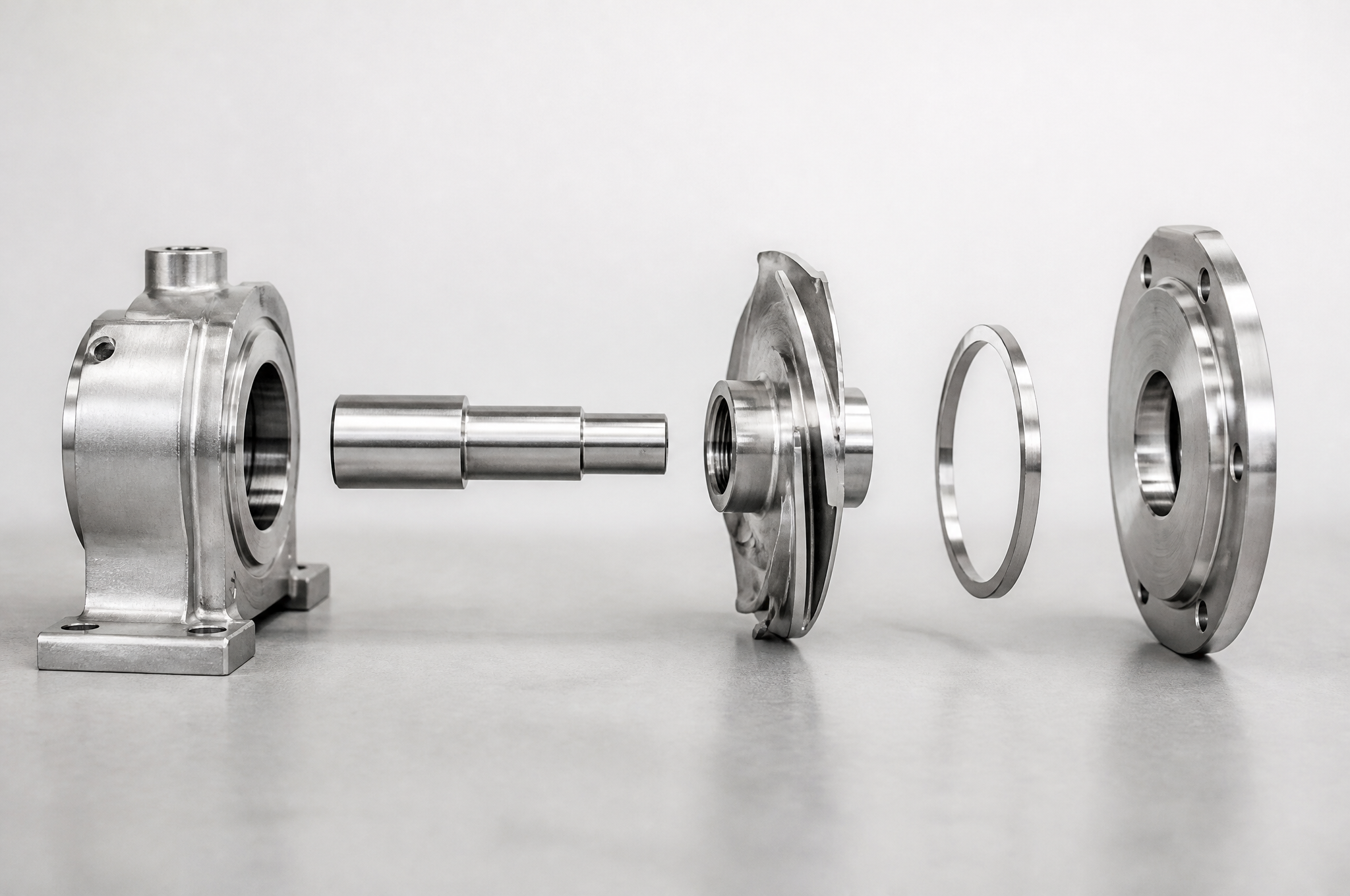
Buyers send drawings one part at a time, and that is the natural way to buy. But the parts that determine whether a pump runs well are the ones that touch each other, and they are designed as a group even when they are purchased separately: shaft, bearing housing, impeller, wear ring, cover, seal interface.
| What the running behaviour depends on | Which parts set it | What goes wrong when they are made independently |
|---|---|---|
| Radial position of the impeller in the casing | Bearing-housing bore, shaft journal, impeller hub bore | The bore and the journal are each in tolerance but at opposite limits, so the impeller sits off-center and the wear-ring gap is uneven around the circumference |
| Axial position of the impeller | Shaft shoulder, housing face, cover face, shim stack | Stack-up across three parts lands the impeller too close to the cover; the clearance is set by the assembly, and no single drawing owns it |
| Running clearance at the wear ring | Wear-ring bore, impeller eye diameter, concentricity of both | Both diameters correct, both eccentric to the shaft axis, so the gap closes on one side and opens on the other |
| Seal life | Shaft or sleeve surface under the seal, runout, finish | Finish is to drawing but runout is not, so the seal face oscillates and the leak appears weeks later, attributed to the seal |
| Vibration at running speed | Everything above, plus balance | Balance is the pump builder's operation, but poor concentricity or a bent shaft consumes the balance allowance before it starts |
Five Component Families, and What Decides Each One
Pump component catalogues tend to list every part name in the pump. That is not how a machining review works: what matters is which features on the part carry the running behaviour, because that is what determines the process, the inspection plan and the price. The five families below cover the parts we actually machine, and the last column is the honest answer to “what will be difficult about this one”.
| Family | Typical parts | Features that carry the function | Where the difficulty sits |
|---|---|---|---|
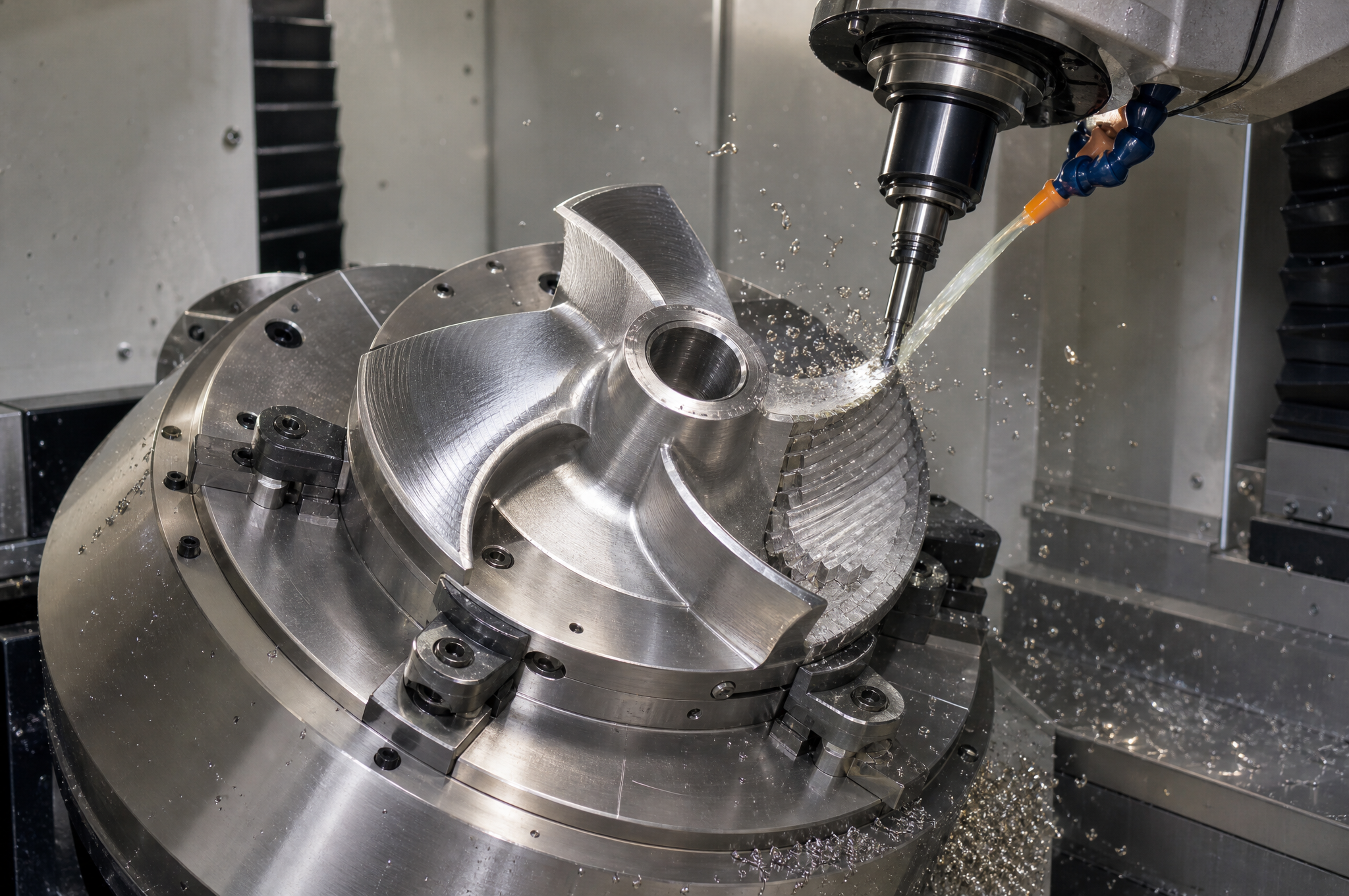
| Impellers and rotating components | Semi-open and open impellers, closed impellers, hubs, rotors, inducer-style parts | Blade envelope, hub bore, eye diameter, back face, runout to the bore axis | Blade surfaces need multi-axis access and a consistent tool path; a closed impeller with narrow passages may not be machinable from solid at all, and that has to be established before quoting |
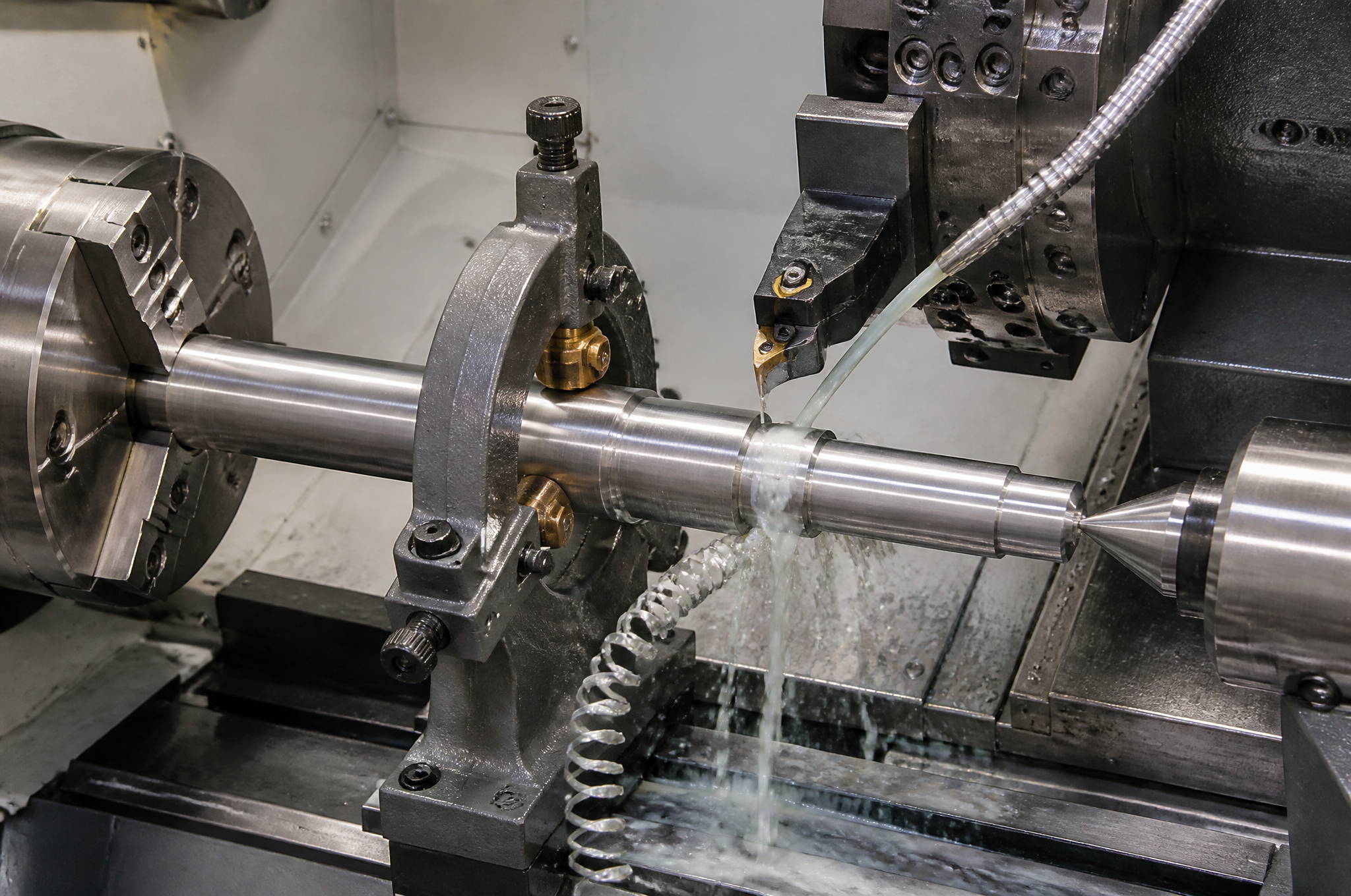
| Shafts and rotating transmission | Pump shafts, drive shafts, stepped shafts, stub shafts | Journal diameters, shoulders, keyway, thread, bearing seats, total runout | Length-to-diameter: a long shaft deflects under cutting force unless it is supported, and every support becomes a witness on the finished diameter |
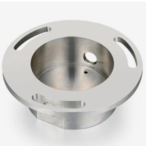
| Housings and bearing seats | Bearing housings, bearing brackets, pump covers, end covers, seal housings | Bore diameter and roundness, bore-to-face squareness, position of the mounting pattern, seal-face flatness | Bore roundness after clamping, thin-wall distortion near a flange, and holding squareness between a bore and a face that are machined from different directions |
| Flanges, adapters and mounting parts | Discharge and suction flanges, adapter plates, motor adapters, spacer plates, base brackets | Bolt-circle position, spigot diameter, face flatness, parallel faces, thread depth | Bolt pattern and spigot have to keep a positional relationship; two faces parallel to each other are easy, two faces parallel to a spigot are not |
| Bushings, wear rings and sleeves | Wear rings, throat bushings, shaft sleeves, distance sleeves, journal bushings | Bore and outside diameter, wall thickness, roundness, concentricity, hardness and surface finish | Thin rings deflect when clamped; a ring held in a three-jaw chuck is not round by the time it leaves the machine, so they need a bore-and-mandrel sequence |
Bushings, wear rings and shaft sleeves sit closest to the mechanical seal components we machine, and some of them are the same parts under a different name. That is why the seal page exists as a separate destination: if your enquiry is about a seal seat, a gland, a sleeve or a seal housing, it is answered there with the seal-specific material and wear detail, and this page links rather than repeats.
Choosing the Process From the Geometry, Not From the Machine List
The same pump part can often be made two ways, and the cheaper way is decided by the geometry and the quantity rather than by which machine is free. The table is how we route a pump enquiry.
| Part condition | Route we take | Why | What it costs the buyer |
|---|---|---|---|
| Rotationally symmetric, features coaxial | CNC turning, one or two setups | Everything is generated from one axis, so concentricity is free | Nothing extra; this is the cheapest pump geometry |
| Shaft with a keyway, cross hole or flat | Turn, then mill; or turn-mill in one clamping | The off-axis feature has an orientation relative to the axis | A second operation unless the machine has live tooling; either way the keyway becomes a controlled position |
| Bore and face that must be square to each other | Single-setup boring, or bore-then-face without releasing | Squareness disappears the moment the part is re-clamped | Boring from one side only, occasionally at the expense of a larger tool overhang |
| Blade or vane surfaces | 5-axis simultaneous milling | The surface is continuous in two directions; a 3-axis path leaves steps the seal of the flow cannot tolerate | Machine hour rate, and programming time that has to be paid once |
| Thin rings and bushings | Turn between centers or on a mandrel; bore, then finish outside | Clamping force is what makes a ring out of round, not the cutting | An extra operation, and a mandrel per diameter |
| Hardened or wear-resistant surface | Turn or mill soft, heat treat, then grind | Hardening moves the part; grinding is what restores size and roundness afterwards | A two-stage order with an allowance, and a grinding operation after heat treatment |
| Deep bore with a tight finish | Drill, bore, then hone or roller-burnish | A single-point tool at depth leaves a finish and a taper that a bore gauge will find | One more operation, but usually cheaper than tightening the boring tolerance |
| Low volume, complex housing | Machined from solid | No pattern or die to amortise | Material removal time and scrap value; at higher volume a casting review is the better conversation |
Critical Features: The Eight That Decide a Pump Component
This is the part of the page most worth reading before releasing a drawing, because every one of these features has a way of passing inspection and still causing a problem in the pump.
| Feature | Why it matters in service | How it is normally verified | What decides whether it is achievable |
|---|---|---|---|
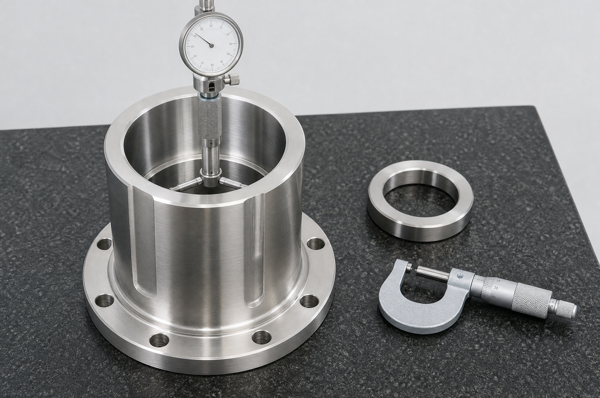
| Bearing bore | Sets bearing position and preload; a bore out of round transfers its shape to the outer ring | Internal micrometer or bore gauge at two depths and two directions; CMM for roundness and cylindricity | Whether the bore is finished after the part is released from the chuck, and whether the wall around it is stiff enough |
| Bore-to-face squareness | A bearing seated on a face that is not square to its bore tilts, and the shaft runs at an angle | CMM with a datum established on the bore, or a squareness check on a surface plate | Machining the face and the bore without re-clamping; if they must be done separately, the second operation has to be datumed on the first |
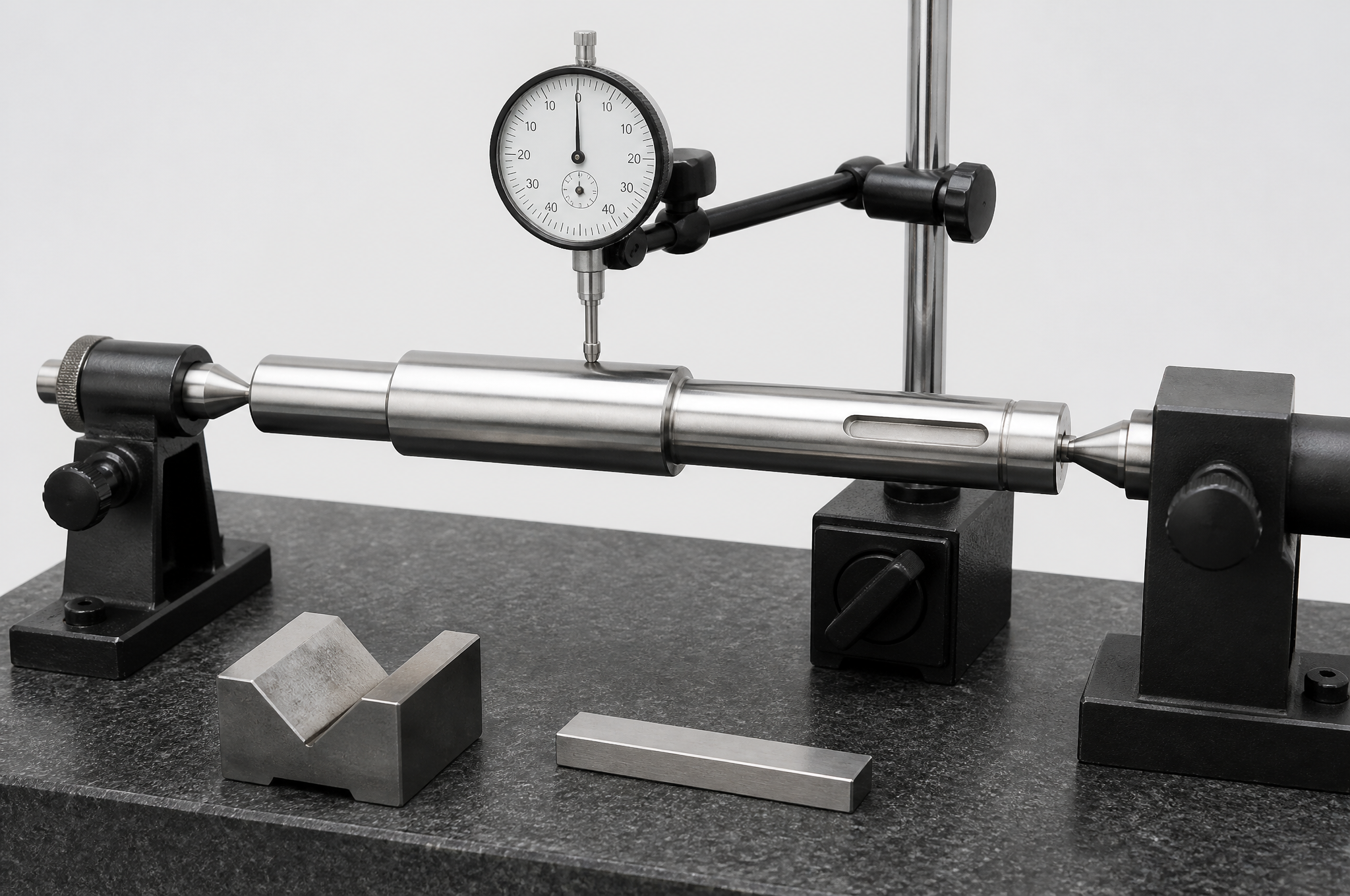
| Shaft journal diameter and roundness | Bearing fit and oil film; an out-of-round journal beats the bearing | Micrometer at several sections; V-block and indicator for roundness where specified | Deflection during turning, and whether the journal is ground after heat treatment |
| Total indicated runout | The seal, the bearing and the impeller all inherit the runout of the surfaces they sit on | Between centers or in V-blocks with a dial indicator; CMM for a full revolution scan | Whether the datum is the centers, the bearing journals or the coupling end — the number only means something with the datum stated |
| Seal face flatness | A seal land that is not flat leaks regardless of the elastomer | Optical flat or CMM scan; surface roughness instrument for Ra | Lapping or fine boring as a separate operation; a turned face is usually not flat enough for a hard seal |
| O-ring groove width and depth | Groove volume sets the compression; a shallow groove over-compresses and a wide one lets the ring move | Groove micrometer, or a profile trace on a CMM | Tool width tolerance and whether the groove is cut in the same setup as the face it sits in |
| Wear-ring bore and concentricity | The running clearance is set here; eccentricity closes the gap on one side | Bore gauge plus a concentricity check against the locating diameter | Holding a thin ring without distortion, and boring it in the same setup as its locating face |
| Keyway and thread | Transmit torque and hold the impeller nut; both fail as assemblies, not as features | Keyway width by gauge or CMM; thread by go/no-go gauges | Whether the keyway is cut after the shaft is finished, because broaching or milling it can move the shaft |
Clearance Is a System Property, Not a Dimension
The single most common misunderstanding on a pump component order is that a clearance can be specified on one drawing. It cannot: a running gap is created by two or three parts, each with its own tolerance, and the assembly inherits the sum. The table shows how that arithmetic behaves, and what to do about it.
| Situation | What the arithmetic does | Practical consequence | Better instruction on the drawing |
|---|---|---|---|
| Bore and shaft each at mid-tolerance | Nominal clearance, and the design intent is met | The good case; most assemblies land here | Nothing to change |
| Bore at maximum, shaft at minimum | Clearance at its widest; the joint can rattle or the seal can lose preload | Function loss without any dimension being out of tolerance | State the fit (for example H7/h6) rather than two independent limits |
| Bore at minimum, shaft at maximum | Clearance at its tightest; assembly needs force and the bearing runs hot | The part is scrapped at assembly, not at inspection | Same: replace independent limits with a fit callout |
| Two parts concentric individually but offset as a pair | Clearance varies around the circumference while the average stays nominal | Uneven wear-ring gap, side load, vibration | Specify concentricity or runout relative to a shared datum, not just diameters |
| Assembly stack-up across three parts | Three tolerances add; the axial gap is the sum | The impeller sits too close or too far from the cover | Nominate one part as the adjustable element, or specify a shim allowance |
Materials Chosen Against the Medium, Not the Grade Name
Material selection is where a pump component enquiry most often contains a hidden assumption. A drawing says 316L because the last pump was 316L, and nobody checks whether the medium, the temperature or the chloride level has changed. The table below lists what we machine and, more usefully, the condition under which each is the wrong choice.
| Material | Where it is the right answer | Where it is the wrong answer | What to confirm before ordering |
|---|---|---|---|
| 304 stainless | Clean water, mild process fluids, general industrial service | Chloride-bearing water, brackish or marine duty, and anything that will sit wet between runs | Chloride level, temperature, and whether the part is wetted or only splash-exposed |
| 316 / 316L stainless | Moderate chloride and chemical exposure, food-adjacent and pharmaceutical water | Warm, concentrated chlorides and some acids where pitting or stress-corrosion is likely; also not a substitute for a duplex grade in high-chloride seawater duty | Actual chloride concentration and temperature together — neither on its own decides it |
| Duplex / super-duplex stainless | Seawater, high-chloride and high-strength combinations | Where the grade is specified but the machining allowance was priced as 316L; duplex work-hardens and needs a different route | Whether the required grade is available in the stock form and size, and whether it is weldable in the intended assembly |
| Aluminum 6061-T6 | Lightweight non-wetted parts, cooling-water components, adapters, brackets | Wetted surfaces in most process fluids; galvanic contact with stainless in a wet environment | Whether the part touches the medium, and whether an anodized finish is acceptable at the sealing face |
| Bronze and brass alloys | Wear rings, bushings, impeller wear surfaces, some seawater duty with the right alloy | Ammonia-bearing or certain chemical media; and any assumption that “bronze” means one material — the alloy family covers a wide range | The specific alloy designation, its hardness relative to the mating part, and the medium's compatibility |
| Carbon and alloy steel | Shafts and structural parts where strength governs and corrosion is handled by coating or by a dry environment | Wetted or humid service without a finish; also where the coating can be damaged at assembly | Heat-treatment condition, and whether the finish is protective or only cosmetic |
| Duplex-grade cast equivalents and cast stainless | Housings where the geometry or the volume favours a casting with machined interfaces | Prototype quantities, or where the pattern cost cannot be justified | Whether the route is casting plus machining, which is a separate quotation |
| PEEK, PTFE, POM | Bushings, wear pads, insulating parts, low-friction guides | High-pressure sealing faces (PTFE creeps), and any location where thermal expansion is constrained | Temperature, pressure, creep allowance, and whether the medium attacks the polymer |
Seal Faces, Bearing Seats and the Finish That Actually Matters
A drawing that says “Ra 0.8 all over” is telling the shop to waste time on surfaces that do not care, and it is not telling them enough about the two surfaces that do. Finish on a pump component should be specified where it functions.
| Surface | What the finish is doing | How it is produced | What to specify |
|---|---|---|---|
| Seal land | Provides the flat, low-roughness face a mechanical seal runs against | Fine boring, then lapping where the drawing requires it | Flatness and Ra together; one without the other is not a seal face |
| Shaft or sleeve under the seal | The elastomer or the seal face bears on it while rotating | Turning, then grinding or polishing to size | Ra plus runout plus hardness — a soft, rough surface wears the seal packing |
| Bearing seat | Controls the interference fit and the seating contact | Finish boring or grinding | Diameter, roundness and Ra together; a mirror finish is not required, roundness is |
| O-ring groove | Retains the ring and sets its compression | Grooving tool in the same setup as the face | Width, depth and corner radius; a sharp groove corner cuts the ring at assembly |
| Gasket faces | Distribute bolt load without a leak path | Facing or milling | Flatness across the bolt circle, and a finish the gasket can bite into |
| Wear-ring bore | Sets the running clearance and takes the wear | Boring, honing where specified | Diameter, roundness and a finish that holds a lubricating film rather than a mirror |
| External surfaces | Corrosion resistance and appearance only | As-machined, blasting, passivation, painting | Call it once, and keep it off the functional faces |
Two finishing details that change dimensions and are often discovered late. Passivation does not move a dimension; electropolishing does — it removes material, so a bore grows and an edge rounds, and a seal land that was lapped to flatness before electropolishing will not be flat after it in the same way. Coating builds on threads and fits — a plated or coated shaft journal is no longer the diameter the bearing was specified against unless the coating was masked or the allowance planned.
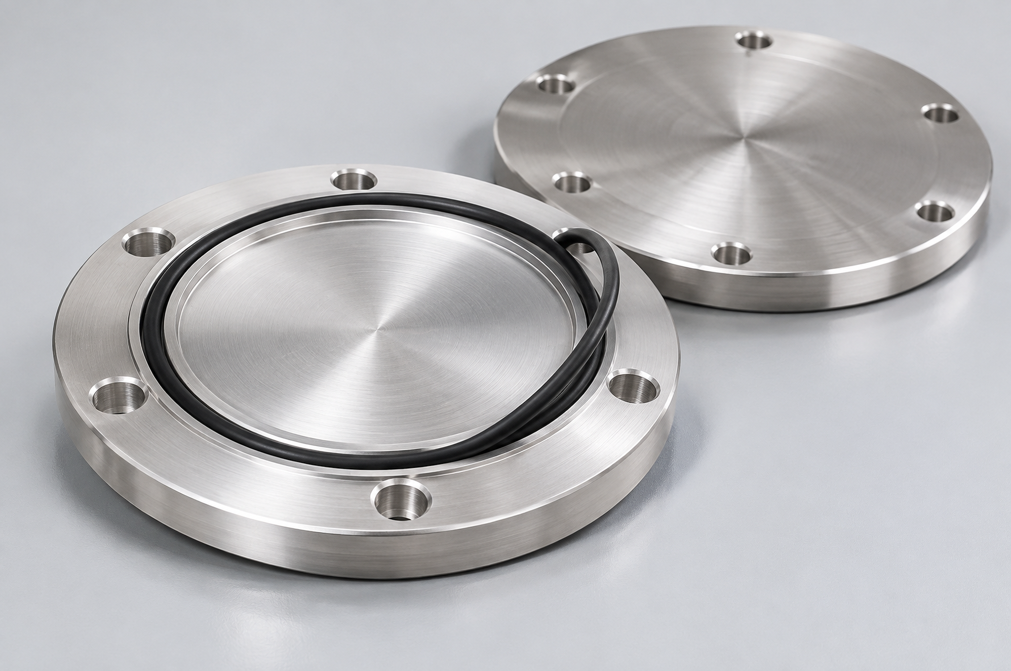
Machining Components as a Matched Set
Where a customer can supply drawings for the parts that touch each other, we will machine them as a set and evaluate the interfaces across the drawings rather than one part at a time. It is not a different process; it is a different review, and it is the cheapest way to avoid an assembly that does not close.
| Set | Interface we check across the drawings | What we report |
|---|---|---|
| Impeller and shaft | Hub bore against shaft diameter; shoulder face against impeller back face; keyway position against impeller keyway | Measured bore and journal, and the resulting fit range across the set |
| Shaft and bearing housing | Journal diameter against bore; axial location of the bearing against the housing shoulder | Bore and journal data with the fit range, plus bore roundness |
| Impeller and wear ring | Eye diameter against ring bore; concentricity of each to the shaft axis | Radial clearance range, and runout of both parts to their locating diameters |
| Cover and seal interface | Seal land position and squareness against the bore axis; groove depth against the specified ring section | Squareness and flatness data, groove measurement |
| Flange and mounting interface | Bolt circle against spigot; face flatness against the mating face | Position data per hole and flatness across the face |
Replacement Components When There Is No Drawing
A large share of pump component enquiries are for replacements: the original part is worn, the OEM lead time is long, or the pump is old enough that the drawing no longer exists. That work is possible, but it starts with a measurement decision rather than with a machining decision.
Photographs, part numbers, pump model and nameplate data all help and none of them replace the measurement. Where the sample is heavily corroded or cracked, the honest answer may be that the part cannot be reproduced from it and a drawing or a mating assembly is needed.
Inspection and Traceability for Pump Components
A pump OEM's supplier quality specification usually asks for more than a dimensional report: material traceability to the heat, part marking, protection of machined surfaces in transit, calibrated instruments, in-process checks and a final inspection record. Those are reasonable, and they are the items we plan for on a pump order rather than improvise.
| Document or record | What it establishes | When it is issued |
|---|---|---|
| Material certificate | Grade, heat number and condition of the stock | With the order; EN 10204 3.1 where the drawing or purchase order requires it |
| First article inspection report | Full dimensional verification of the first part against the drawing | On the first part of a new revision or a new order, before the run continues |
| Dimensional inspection report | The measured values of the characteristics in the agreed plan | Per batch, or per the sampling agreed at quotation |
| Bore and runout records | Roundness and TIR on the features that set the running behaviour | With the batch report on pump components, because diameters alone are not enough |
| CMM program report | Position, form and orientation against the drawing datum frame | Where the drawing carries GD&T or the geometry is not reachable with hand tools |
| Surface finish record | Ra on the named functional surfaces | Where the drawing specifies Ra on a seal land, journal or bore |
| Batch and marking record | Which parts came from which stock and which run | Per order, with the marking method agreed with the customer |
The measurement has to reproduce the drawing's datum. A runout value taken between centers and a runout value taken from the bearing journals are different claims about the same shaft, and a CMM program aligned to its own convenience will report numbers that satisfy nobody at the assembly bench. That is why the datum frame is the first thing we confirm on a pump drawing, before the process is chosen. Our management system is certified to ISO 9001:2015; where a customer's industry requires a scheme approval beyond that — API, marine class, or a pump OEM's own supplier approval — it is resolved during supplier qualification for that project and is not implied by this page.
From One Prototype to a Repeat Order
Pump development usually starts before the drawings are final, which means the first parts are made from a model that will change. Knowing what changes at each stage keeps the second order from costing as much as the first.
| Stage | What the customer is testing | What we do differently | What must be frozen before the next stage |
|---|---|---|---|
| Fit prototype | Whether the part physically fits the pump | Straightforward machining to the model; finish left as-machined where it does not affect fit | Nothing — this stage is expected to change |
| Functional sample | Whether it runs, seals and wears acceptably | Material condition and the functional finishes are fixed, because a finish can change a fit | Material grade and condition, and the datum scheme |
| Pre-production batch | Whether the process repeats | Fixture or soft jaws justified; first article inspected and reported; in-process checks added | Drawing revision, process route, inspection plan |
| Repeat production | Consistency across orders | Program, fixture and inspection plan held against one drawing revision; any change to them treated as a change | The revision itself — it becomes the controlled reference |
What to Put in a Pump Component Enquiry
The list below is the difference between a quotation and an estimate. Every item that is missing becomes an assumption, and an assumption on a wetted part is what turns into a change order.
| Item | Why the quotation changes without it |
|---|---|
| 3D model and 2D drawing at a named revision | The model defines the shape; the drawing defines the datum, the fits and what is acceptable |
| Component type and function | A shaft, an impeller and a housing take different routes and different inspection |
| Material grade and condition | Grade, temper and stock form decide machinability and whether a stress-relief step is needed |
| Medium, concentration and temperature | Moves the material choice and the finish, more often than the drawing does |
| Wetted, splash or dry | Decides whether a cosmetic finish is acceptable or a corrosion-resistant one is mandatory |
| Critical dimensions and fits | Bore, journal, runout and seal-face calls are what the price and the inspection plan are built from |
| Surface finish and treatment | Lapping, grinding, passivation or coating each add an operation and may move a dimension |
| Inspection and documents required | FAI, CMM report, material certificate and marking are quoted separately from machining |
| Quantity and expected annual demand | Decides fixture investment and whether a casting route should be reviewed instead |
| Mating parts or the pump assembly reference | Lets the interfaces be checked across drawings instead of one part at a time |
| Sample, if it is a replacement | Starts the measurement decision: which surfaces are references and which are reconstructed |
Frequently Asked Questions
Can you manufacture custom CNC pump components from drawings?
Which pump components do you machine?
Can you machine a pump impeller from solid material?
What is the difference between your pump components page and the mechanical seal parts page?
What tolerances can you hold on pump components?
How do you control the running clearance between an impeller and a wear ring?
Which materials do you machine for pumps, and how do I choose?
Can you make a replacement pump part from a worn sample with no drawing?
How are pump components inspected and what documents come with them?
Do you balance impellers or pressure-test pump casings?
Can you machine several pump parts as a matched set?
Should a pump housing be machined from solid or cast and then machined?
Send the Drawing and Tell Us What It Runs In
A model and a dimensioned drawing at a named revision, the material grade and condition, the medium and its temperature, the critical fits and finishes, the documents you need and the quantity you expect. If it is a replacement part, send photographs, the pump model and the sample if you can. The review comes back with the route, the features that will decide the price, and anything that cannot be made or measured as drawn — before a program is written.
Request a Pump Component QuoteSTEP · IGES · X_T · DWG · DXF · PDF · NDA on request
Related Pages
Pump mechanical seal parts
Seats, glands, sleeves, holders and seal housings, with the seal-specific material and wear detail. Seal components
CNC machining services
Equipment, envelope, published tolerance tables and the plant behind these components. Machining capability
CNC turning services
Shafts, sleeves and bushings, including slender work with steadies and between-centers turning. Turning
5-axis machining
Impeller blades, contoured passages and multi-face parts cut without re-clamping. Five-axis work
Die casting services
For housings where a casting plus machined interfaces is the right route. Die casting
Quality and certifications
What the quality system covers, which documents are issued, and what is not claimed. Quality
Surface finishing
Passivation, electropolishing, plating and blasting, and the dimensional effect of each. Finishing
Materials
The full grade library behind the materials section above. Materials
Prototype to production
How a part moves from a first-off sample to a controlled repeat process. Production support