Design and manufacture lightweight plastic components with thin sections while controlling filling, cooling, warpage, weld lines and dimensional consistency. This guide explains the engineering factors that determine whether a thin-wall part is manufacturable.
- High-Flow Materials
- High-Speed Filling
- Precision Tooling
- Process Validation
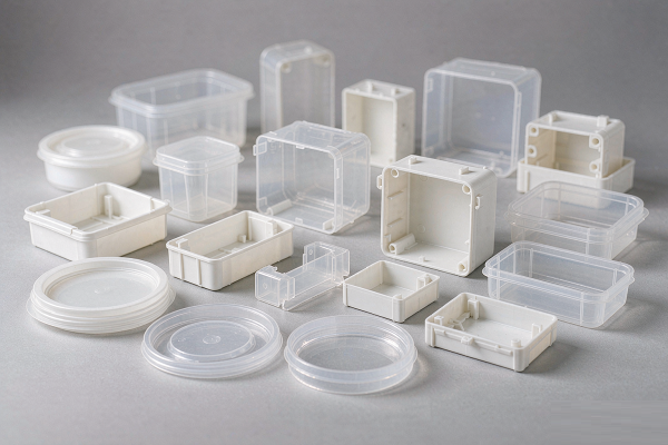
The short answer: thin-wall molding is not "the same part with less plastic". Reducing wall thickness shortens the time the melt has to fill the cavity, raises the pressure needed to push it there, and narrows the process window. Whether a thin wall is manufacturable depends on wall thickness, flow length, resin flowability, gate strategy, venting, cooling balance and mold rigidity — evaluated together, not one at a time. This page explains how each variable behaves and where thin-wall programs usually fail.
On This Page
Thin-Wall Injection Molding at a Glance
Ten variables that decide whether a thin-wall part fills, cools and holds dimension — the summary of this entire page.
| Factor | Why It Matters in Thin-Wall Molding |
|---|---|
| Wall thickness | Sets flow resistance and how quickly heat is lost to the mold steel |
| L/T ratio | Indicates how far the melt must travel relative to the wall thickness — the single most useful feasibility indicator |
| Resin flowability | Higher-flow grades fill thin sections more easily and reduce the pressure demand |
| Injection speed | Determines whether the cavity is filled before the melt front freezes |
| Injection pressure | Must overcome flow resistance without exceeding machine, mold or flash limits |
| Gate location | Sets flow length, fill balance and where weld lines and air traps land |
| Venting | Fast filling leaves little time for air to escape; trapped air causes burns and short shots |
| Cooling | Controls shrinkage uniformity, cycle time and warpage |
| Mold rigidity | High cavity pressure demands a stiff, well-supported tool with reliable shut-offs |
| Geometry & orientation | Governs flow path, stiffness of the finished part and how it distorts |
When a thin-wall quote comes back "not feasible", it is almost always one of these ten rows — usually flow length or gating, not the nominal wall thickness itself. Ask which one, and the conversation becomes an engineering problem instead of a yes/no.
What Is Thin-Wall Injection Molding?
And why a single thickness threshold is the wrong way to define it.
Thin-wall injection molding generally refers to molding parts with unusually thin sections relative to their size and flow length. Depending on the application, material and process, thin-wall parts may be characterised by absolute wall thickness, by a high length-to-thickness (L/T) ratio, or by both.
That definition is deliberately loose, because the reality is loose. A wall that is routine on a small, short-flow component can be genuinely difficult on a large housing where the melt has to travel several hundred millimetres through the same narrow gap. Treating a single number as the boundary between "conventional" and "thin wall" produces bad design decisions in both directions: parts that get over-engineered because someone assumed thin was risky, and parts that get tooled because 0.8 mm sounded safe on paper.
Wall Thickness vs Flow Length: Why L/T Ratio Matters
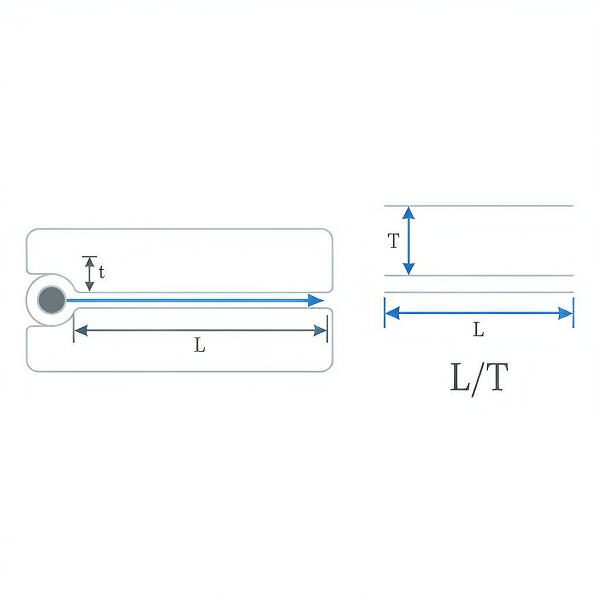
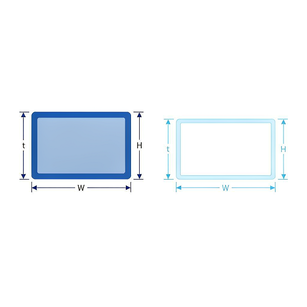
The length-to-thickness ratio compares how far the melt must travel (L) against the thickness of the channel it travels through (t). It is more predictive than thickness alone because it captures the two things that actually resist flow: distance and narrowness.
Consider three cases with the same nominal design intent:
- 1.0 mm wall, short flow path — often manageable with a suitable resin and a well-placed gate.
- 1.0 mm wall, long flow path — considerably more demanding; pressure requirement rises and the fill window narrows.
- 0.6 mm wall, long flow path — significantly more challenging; may require high-flow resin, multiple gates, elevated mold temperature and a machine with the speed and pressure to match.
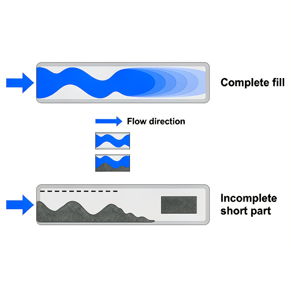
The melt does not experience "a wall thickness"; it experiences a progressively cooling stream losing pressure as it advances. Long travel through a thin section means the front cools more before it arrives, so the last region to fill is filled by the coldest, most viscous material — which is exactly where short shots, weld lines and burn marks appear.
Why There Is No Universal Thin-Wall Limit
Because fillability is a system property. The same 1.0 mm section behaves differently depending on the resin's flow characteristics, the gate's position and number, the steel temperature, the venting at the end of fill, and whether the machine can deliver the required injection speed. Published thickness thresholds are useful as conversational shorthand and misleading as engineering criteria.
The practical position we take: thin-wall feasibility should be evaluated from geometry + flow length + material + gating + machine capability together, not from wall thickness alone.
Why Is Thin-Wall Injection Molding Difficult?
One change — a thinner wall — sets off a chain that ends in a narrower process window.
1. Premature Freezing
The melt enters the cavity hot and begins losing heat to the mold steel immediately. In a thick section there is enough volume that the core stays molten while the surfaces skin over. In a thin section, the whole thickness approaches the freeze temperature quickly, so viscosity climbs during filling. If the front freezes before the cavity is full, you get a short shot — and it typically appears at the last point to fill, not randomly.
2. Higher Pressure Requirement
Flow resistance rises steeply as the channel gets thinner and longer. Filling the same projected area through a 0.6 mm wall instead of a 1.2 mm wall can require substantially more injection pressure. That has knock-on consequences: more clamp force to resist flash, more mold deflection, more stress on shut-offs and slides, and a machine that must be capable of both speed and pressure simultaneously.
3. Faster, Less Forgiving Cooling
Thin sections reach ejection temperature quickly, which is part of why thin-wall molding can offer shorter cycles. But speed cuts both ways: the part also becomes more sensitive to small cooling differences. A hot spot that a thick section would absorb can visibly distort a thin one.
4. Warpage and Shrinkage Sensitivity
A thin wall has low structural stiffness while it is hot and semi-molten. Uneven cooling, uneven packing, or fibre orientation in filled grades all translate into distortion more readily than in a thick, rigid section. Warpage in thin-wall parts is rarely a "material problem" alone — it is usually a cooling-balance or orientation problem expressing itself.
5. Weld Lines and Air Traps
Short fill windows make the flow front less forgiving. Where two fronts meet, the weld line is weaker because the material has cooled and the molecules have had less time to entangle across the interface. Where air cannot escape ahead of a fast front, it compresses, heats and can burn the polymer at the surface. Both are strongly influenced by gate placement and venting — decisions locked in during mold design.
Flow resistance rises beyond what the available pressure can comfortably overcome.
Viscosity climbs mid-fill; the last region to fill receives the coldest material.
Faster filling and higher pressure are used to buy back the lost window.
Small variations in temperature, viscosity or vent condition now matter.
Short shot, flash, burn marks, weld lines, warpage — often several at once.
Thin-Wall Injection Molding Design Guidelines
Six rules that prevent most thin-wall problems before the tool is cut.
These are not aesthetic preferences. Each one exists because violating it changes how the melt fills, cools or releases — and in a thin-wall part there is less margin to absorb the consequence.
Keep Wall Thickness as Uniform as Practical
Uniform wall thickness is the foundation of thin-wall design. Where sections differ, the thin region fills last and freezes first while the thicker region is still shrinking — a combination that produces internal stress, warpage and dimensional variation.
Where uniform thickness is impossible, keep the variation as small as the function allows and place the transition away from critical features.
Transition Gradually, Never Suddenly
An abrupt step from a thick section to a thin one creates a flow restriction, a stress concentrator and a visible flow mark. Step the change down over several stages instead.
In practice: 1.5 mm → 1.1 mm → 0.8 mm with generous radii, rather than 1.5 mm → 0.6 mm in one step.
Design Ribs and Bosses Thinner Than the Nominal Wall
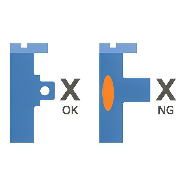
Ribs add stiffness without adding material across the whole surface, but a rib that is as thick as the wall creates a local mass of material that cools more slowly and sinks on the opposite face.
A typical starting point is rib thickness around 50–60% of the nominal wall, subject to the material's flow behaviour and the structural requirement. Glass-filled grades and high-shrinkage resins may need a different ratio, so treat the figure as a starting point for review, not a rule.
Bosses and Local Thick Sections
Bosses for screws or inserts are the classic thin-wall trap: a solid cylinder attached to a thin wall is exactly the geometry that sinks and warps. The usual responses are to core the boss out so its wall is comparable to the nominal wall, to connect it to the wall with ribs or gussets rather than a solid junction, and to keep the base radius generous.
Where a boss genuinely needs more material for thread engagement, isolate it and accept a local cosmetic compromise knowingly, rather than discovering it at T1.
Keep Draft, Even on Short Walls
There is a persistent belief that thin walls do not need draft because they are short. The opposite is often true. A thin wall has little rigidity during ejection, and a tall thin wall with zero draft can stick, deform or tear as the part is pushed off the core.
Apply draft consistently on all vertical faces that form in the tool. Where a cosmetic or functional requirement forbids draft, flag it early — it usually means a slide, a lifter or a different parting strategy, all of which affect tooling cost.
Add Radii and Fillets
Sharp internal corners do three bad things at once: they restrict flow, they concentrate stress in the finished part, and they create a sharp edge in the steel that is harder to machine accurately and more prone to wear or chipping.
Generous radii at rib bases, wall junctions and around bosses improve fill, reduce stress concentration and extend tool life. External corners benefit too, since they aid release.
Place Holes and Features With Flow in Mind
Holes, slots and windows interrupt the flow front. Each one creates two flow paths that must rejoin — a weld line — and each one creates a shut-off area in the steel that must seal against high injection pressure.
Where possible, orient features so that the flow rejoins in a non-critical, non-cosmetic region, and keep holes away from the last area to fill. Features formed by shut-off steel also deserve attention in the tooling review, because a shut-off under thin-wall pressures is a flash risk.
Material Selection for Thin-Wall Injection Molding
Flowability gets the cavity filled. Everything else decides whether the part survives service.
| Material | Thin-Wall Consideration |
|---|---|
| PP (Polypropylene) | Excellent flowability and low density; the default choice for many lightweight thin-wall parts and living-hinge features. Shrinkage is relatively high and needs to be designed for. |
| PE (HDPE / LDPE) | Good flow and chemical resistance; widely used in thin-wall packaging and containers. Flexible grades reduce the risk of ejection damage. |
| ABS | Useful where appearance, rigidity and paintability are required. Flow is more limited than PP, so very long thin flows need careful gating review. |
| PC (Polycarbonate) | High impact and heat performance, but more demanding to fill in thin sections — typically needs higher melt and mold temperature and careful drying. Gate and vent design become critical. |
| PA (Nylon, incl. GF) | High strength and wear resistance. Unfilled PA flows reasonably well; glass-filled grades are stiffer but the fibres make shrinkage directional, which complicates warpage in thin plates. Moisture control is essential. |
| PC/ABS | A practical balance of impact, flow and surface quality for housings and covers. Often chosen when a thin cosmetic enclosure also needs toughness. |
| POM (Acetal) | Low friction and good dimensional behaviour for precision mechanisms. Crystalline shrinkage is significant, so thin sections need careful tolerance and process review. |
| PEEK | Specialised high-temperature engineering resin. Processed for demanding applications where the performance justifies the material and processing cost; not a general thin-wall choice. |
Why Melt Flow Matters — and Why It Is Not the Only Criterion
Melt flow behaviour describes how easily a molten resin moves under pressure. In thin-wall molding this matters directly: a higher-flow grade generally fills thin sections more easily, demands less injection pressure, and reduces short-shot risk. When a part will not fill, switching to a higher-flow grade is often the first lever considered.
It is also the lever most often pulled too far. Higher flow is usually achieved through lower molecular weight, and that can trade away impact strength, stress-crack resistance, heat performance and long-term durability. A thin-wall part already carries more molded-in stress because it is filled fast under high pressure; selecting a resin with marginal mechanical performance on top of that is how parts pass T1 and fail in the field.
Choose the resin from flowability and final-part performance together, not from flowability alone. Define the service requirements first — temperature, chemical exposure, mechanical load, impact, regulatory position, appearance — then find the grade within that set that fills the geometry. If no grade satisfies both, the geometry needs to change, and it is far cheaper to learn that during DFM than after steel is cut.
Practical Material Questions Worth Asking Early
- Is the flow length compatible with this resin's flow behaviour? Ask for a fill analysis or an L/T assessment before finalising.
- Is the resin dried and handled correctly? Moisture-sensitive grades such as PC, PA and POM degrade in processing, and degradation shows up fastest in thin, high-shear sections.
- Does the part need a filled grade? Glass fibre improves stiffness but makes shrinkage directional — a real warpage driver in thin plates.
- Is a high-flow grade available in the required colour, approval or regulatory position? High-flow variants do not always exist in every certification.
Gate Design for Thin-Wall Parts
The gate decides flow length. Flow length decides whether the part fills.
Gate location is the single most consequential decision in a thin-wall tool, because it sets the distance the melt must travel through the thin section. The causal chain is direct:
Gate Location
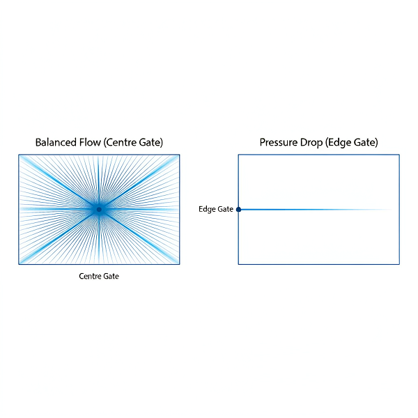
A centrally located gate on a symmetrical part halves the longest flow path compared with an edge gate, which can be the difference between a comfortable fill and an impossible one. Multi-gate layouts reduce flow length further but introduce weld lines where the fronts meet — so the trade is shorter flow against more weld lines, and their position must be acceptable.
Gate Size and Type
Thin-wall gates are usually kept relatively generous in cross-section to limit shear and pressure loss, while remaining small enough to be trimmed cleanly or to freeze off quickly. Common choices include edge gates, fan gates for wide thin edges to promote a straight flow front, and hot runner direct or valve gates for multi-cavity production tools where runner loss and balance matter.
Gate size also affects packing. Too small a gate can freeze off before the part is adequately packed, leaving shrinkage and dimensional variation that no amount of holding pressure can correct.
Number of Gates and Fill Balance
In multi-cavity or multi-gate tools, balance is the objective: every flow path should fill at the same time and under the same pressure. Unbalanced filling means one cavity is over-packed while another is short, and the defect moves around as conditions drift. Naturally balanced runner layouts or a properly balanced hot runner system are designed in, not tuned in.
Venting Design
Fast filling and trapped air are direct opponents. Thin-wall molding makes the conflict worse.
A filling cavity has to push the air inside it out ahead of the melt. In conventional molding there is more time for that air to escape through parting-line gaps, ejector clearances and dedicated vents. In thin-wall molding the cavity fills in a fraction of the time, so the same air volume must leave through the same paths far faster.
When it cannot, the air is compressed by the advancing front. Compression heats it, and at thin-wall filling speeds the temperature can be high enough to burn the polymer surface. The result is a burn mark at the last point to fill — frequently mistaken for a material problem when it is a venting problem.
Where Venting Is Reviewed
- End of fill — the primary location; identified from fill analysis, not guessed.
- Around shut-offs and cores — slender cores and blind ribs trap air easily.
- Behind weld line locations — where two fronts converge, air is pushed into the junction.
- Ejector pins and inserts — clearances that help venting must be maintained, not polished away.
Venting Depth Is Material-Dependent
Vent depth has to be deep enough to pass air and shallow enough that the melt cannot pass through into it. That window differs by resin viscosity, so a vent depth that works for a stiff-flow material may flash with a very low-viscosity high-flow grade. This is one reason venting is specified per material rather than copied from the last tool.
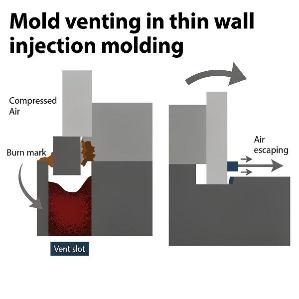
Venting is a mold design outcome. If the end-of-fill location is not known until the first trial, the vents will be in the wrong place, and adding them afterwards means welding, re-machining and re-fitting hardened steel. We identify end-of-fill and venting requirements during mold design.
Cooling System Design
Cooling uniformity is a dimensional control, not just a cycle-time lever.
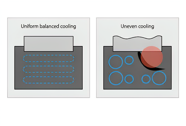
In thin-wall molding, cooling is where geometry is either held or lost. The part is thin, so it reaches ejection temperature quickly — but it is also compliant while hot, so any temperature difference across the tool translates directly into differential shrinkage and then into warp.
Channel Layout and Hot Spots
Cooling channels should follow the part geometry, keeping a consistent distance from the cavity surface. Areas that are hard to reach — deep cores, narrow ribs, inside corners of thin plates — are where hot spots form. In thin-wall tools these often need dedicated solutions: baffles, bubblers, high-conductivity inserts, or in demanding cases conformal cooling channels produced additively.
Thermal Balance Between Cavity and Core
The two halves rarely need identical cooling. The core is usually harder to cool and tends to run hotter, and a part that stays on the hot half will shrink differently on each face — a classic recipe for a thin plate that bows toward the hot side. Balancing the two circuits, and measuring both, is more useful than simply increasing overall flow.
Cycle Time Versus Stability
Thin walls cool fast, which is part of the commercial appeal. But cooling time should be sufficient for the part to hold geometry on ejection. Cutting cooling to shave a second off the cycle often shows up later as parts that measure fine in the machine and drift after they have sat — particularly with semi-crystalline resins that continue to shrink.
Tooling Requirements for Thin-Wall Molding
The tool has to survive the pressure that thin walls demand.
Thin-wall molds work under higher cavity pressure than conventional tools, and that single fact drives most of the special requirements. A tool that would be perfectly adequate for a 2.5 mm wall can deflect, flash or wear prematurely when the same part is produced at 0.8 mm.
Mold Rigidity and Support
High cavity pressure tries to separate the mold halves and deflect the cavity. The tool needs adequate plate thickness, proper support pillars beneath the cavity, and enough clamp capacity from the machine. Insufficient support shows up as flash along the parting line and as dimensional drift between the centre and edges of the part.
Cavity and Core Precision
When the wall is thin, the steel defines the wall directly — there is no material to absorb machining variation. Cavity and core geometry, alignment and shut-off surfaces must be machined and fitted to a standard that keeps the wall consistent around the part. Thin steel sections between cavities also need enough mass to resist deflection.
Shut-Off Integrity
Shut-offs seal against full injection pressure. In thin-wall tools that pressure is higher, so shut-off angles, contact area and fit quality matter more. Poor shut-offs produce flash, which in a thin-wall part is not just cosmetic — it changes the wall and can affect assembly.
Gate and Vent Precision
Gate land dimensions and vent depths sit in a narrow band: large enough to pass material or air, small enough to freeze or seal correctly. These are machined features with real tolerances and they are material-specific, so they are specified per resin rather than reused by default.
Ejection
Thin parts have little rigidity during ejection and can be distorted by poorly distributed ejector force. Ejector layout, pin diameter, and the use of stripper plates or air assistance need to suit the part, and ejection must be balanced against the thin sections that are most likely to stick.
Steel Selection
Steel is selected against volume, resin, wear, corrosion and surface requirement — not by habit. A high-gloss cosmetic thin-wall housing in a glass-filled resin asks something different from a high-volume packaging tool in unfilled PP. We specify the grade per programme rather than defaulting to a single steel, and we will tell you what was chosen and why.
A thin-wall tool usually costs more than a conventional tool for the same part — more precise machining, better steel, more attention to cooling, venting and ejection. That investment is recovered through material saving, shorter cycle time and lower piece price at volume. The economics only work if the volume is there, which is why the next question is always about quantity.
Thin-Wall Injection Molding Process Parameters
Each parameter as a trade-off, not a number to copy.
Published "typical" process values are one of the least useful things a supplier can give you, because every one of these parameters depends on the resin, the wall, the flow length, the gate, the machine and the target quality. What transfers between programmes is the relationship: what each parameter is trying to achieve, and what it costs when pushed too far.
Injection Speed
Fill the cavity before the melt front freezes prematurely. Higher injection speed is one of the primary tools available in thin-wall molding.
Excessive shear heating, burn marks from compressed air, flash at the parting line, and a process that becomes hypersensitive to small variations in viscosity or temperature.
Injection Pressure
Overcome the flow resistance of a thin, often long, flow path. Thin-wall molding commonly requires more available pressure than a conventional part of the same size.
Higher mold stress and deflection, flash, higher clamp force demand, and greater molded-in stress in the part. Machine capability becomes a genuine constraint.
Melt Temperature
A hotter melt is less viscous and widens the filling window before freeze-off. Often raised deliberately for thin sections.
Thermal degradation of the polymer, longer cooling requirement, possible appearance issues, and with moisture-sensitive resins a higher risk of hydrolysis if drying is inadequate.
Mold Temperature
Influences flow, freeze time, surface reproduction, crystallinity in semi-crystalline resins, and warpage behaviour. Higher mold temperature generally helps filling.
Longer cycle time and, if uneven across the tool, differential shrinkage that shows up as warpage rather than as an obvious processing fault.
Holding Pressure
Compensate for shrinkage as the part cools, and hold dimensional consistency between shots.
Thin sections freeze off quickly, so the effective holding window is much shorter than in thick-wall molding. If the gate freezes early, holding pressure has little influence — which makes gate design, not press setting, the determining factor.
Cooling Time
Allow the part to reach a temperature at which it can be ejected without distortion, while avoiding unnecessary cycle time.
Too little cooling and the part deforms on ejection or continues to shrink and drift after packing; too much and the cycle-time advantage that made thin-wall attractive is given away.
Higher injection speed and sufficient available pressure are commonly required to fill thin sections before the melt freezes, but the workable window is established from material data, mold design, machine capability and trial molding — not from a table. Parameters are then recorded at T1 so production can reproduce them, rather than being re-discovered on every run.
Common Thin-Wall Injection Molding Defects
Defect, typical cause, and the engineering response — not just a list of names.
| Defect | Typical Cause | Engineering Response |
|---|---|---|
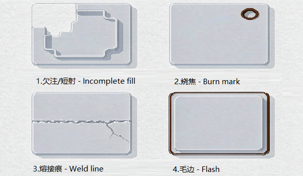
| Short shot | Premature freezing; insufficient flow or pressure; flow length too long for the resin | Review resin flowability, gate location and number, injection speed, melt and mold temperature, and venting |
| Warpage | Uneven cooling or shrinkage; fibre orientation; residual stress | Balance cooling circuits, review wall uniformity and rib layout, re-evaluate gate and orientation |
| Burn marks | Trapped air compressed at the fill front; inadequate venting | Add or deepen vents at end of fill; review fill speed and the flow path that traps the air |
| Weld lines | Multiple flow fronts meeting; flow interrupted by holes or windows | Relocate or add gates, adjust flow strategy, move the junction to a non-critical area |
| Flash | Pressure exceeding clamp or shut-off capability; mold deflection | Review shut-off fit and support, check machine clamp capacity, reassess pressure and speed |
| Sink marks | Local thick sections such as over-thick ribs or bosses cooling unevenly | Correct rib and boss proportions, core out thick sections, improve local cooling |
| Flow marks | Filling instability at the flow front; hesitation at thin or transitioning sections | Review injection speed profile, melt and mold temperature, and gate design |
| Cracking | Residual stress, poor material choice, or stress concentration at sharp corners | Review material grade and drying, add radii, reduce molded-in stress through process adjustment |
| Feature loss | A thin or remote feature freezes before it can be fully formed | Improve the flow path to the feature, review venting, consider local wall or gate changes |
Short Shot
The part is incompletely filled, usually at the point furthest from the gate or in the thinnest remote feature. In thin-wall molding this is the defect that most often appears when a design was approved on wall thickness alone. The response is to widen the filling window: shorter flow path, higher-flow resin, faster fill, hotter melt or mold, better venting — considered in that order of leverage.
Warpage
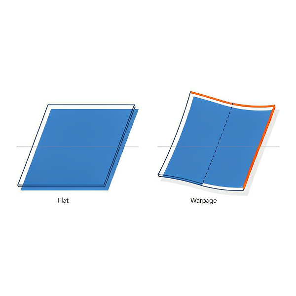
Warpage is a shape error, not a filling error. It comes from shrinkage that is not uniform in magnitude or direction: cooling differences between the two mold halves, fibre orientation in filled grades, or residual stress from fast, high-pressure filling. It is addressed by balancing cooling, reviewing geometry, and in some cases changing gate position so that orientation effects are less damaging.
Flash
Flash occurs when melt escapes into a parting line or shut-off. Thin-wall pressures make it more likely, and thin-wall tooling has to be built to resist it. Persistent flash is usually telling you that the required pressure exceeds what the tool or the machine clamp can hold — which is a design or machine-matching problem, not a setting to be tuned around.
Weld Lines
Where two flow fronts meet, the material has cooled and molecule entanglement across the interface is incomplete, leaving a visible line and a locally weaker region. Weld lines cannot be eliminated when geometry forces fronts to converge, but their position can be chosen. Deciding where that line falls is a gating decision made during mold design.
Burn Marks
Burn marks are a venting signature. Air compressed ahead of a fast-moving front heats enough to degrade the polymer at the surface, typically at the last point to fill. Improving venting at that specific location resolves it; raising melt temperature to "help flow" usually makes it worse.
Flow Marks, Sink Marks and Cracking
Flow marks indicate an unstable front, often where the section changes or where the melt hesitates. Sink marks indicate locally thick material — almost always a rib, boss or junction that is too heavy for the nominal wall. Cracking points to residual stress, sharp corners or a material that is marginal for the application. Each has a different root cause, which is why treating them as one "surface quality" problem tends to fail.
Thin-Wall vs Conventional Injection Molding
Same machine principle, different engineering margin.
| Factor | Conventional | Thin-Wall |
|---|---|---|
| Wall thickness | Standard for the part size | Reduced, relative to size and flow length |
| Filling speed | Moderate | Faster filling generally required; higher sensitivity to speed |
| Pressure demand | Normal | Often substantially higher |
| Material use | Higher per part | Lower per part |
| Cycle time | Normal | Potentially shorter, because thin sections cool faster |
| Tooling sensitivity | Moderate | Higher — rigidity, precision, venting and cooling all matter more |
| Process window | Wider | Narrower; less tolerant of drift |
| Quality control | Standard | More demanding; warpage and dimensional consistency need defined methods |
| Volume orientation | Broad | Often high-volume oriented, because tooling investment is recovered through volume |
Thin-Wall vs Gas-Assisted and Foam Injection Molding
Four ways to remove mass from a plastic part. None of them is universally best.
Weight reduction is the goal; thin walls are only one route to it. Choosing between them depends on what the part has to do — how stiff it must be, what it has to look like, what volume it runs at, and what tooling budget exists.
Thin-Wall Molding
Mass is reduced by making solid walls thinner. Best suited to parts with short-to-moderate flow lengths, high volumes, and geometry that can accept uniform thin sections.
Trade-off: higher pressure, narrower process window, more demanding tooling — recovered through material saving and shorter cycles at volume.
Gas-Assisted Injection Molding
Inert gas is injected into the melt to form a hollow channel, typically in thick ribs or handles. Useful where a part needs thick-looking sections for stiffness without the weight or sink marks.
Trade-off: additional process control and equipment; the hollow path has to be designed in, and wall consistency along the gas channel needs validation.
Foam / Microcellular Molding
A blowing agent creates a microcellular structure, reducing density while retaining wall thickness. Attractive for large, flat parts where thickness gives stiffness but weight is the problem.
Trade-off: surface finish can be affected, and mechanical properties differ from solid material; not a like-for-like substitute in every application.
Structural Ribs and Geometry Optimisation
Stiffness is added through geometry — ribs, gussets, corrugations, domed surfaces — rather than through wall thickness. Often the first and cheapest option to evaluate.
Trade-off: ribs create thick junctions and, on cosmetic faces, sink-mark risk; proportions must be designed, not added.
The right lightweighting method depends on required stiffness, appearance, geometry, annual volume and tooling budget. In practice these approaches are often combined — a modestly reduced wall with well-designed ribs frequently outperforms an aggressive thin wall on both stiffness and manufacturability. If the only argument for thin walls is material cost, it is worth checking whether geometry gets you there more safely.
Thin-Wall Injection Molding Applications
Where thin walls earn their complexity — and what each sector actually demands.
Packaging
Lids, containers, cups, trays and closures. This is the most established thin-wall application: high volume, short cycles, and material cost per part that matters at scale. Living hinges and stacking features often drive the detail design.
Consumer Electronics
Housings, covers, bezels and internal structural parts. Thin walls support lightweighting and compact packaging, but these parts usually carry cosmetic requirements and tight assembly fits, so warpage control and gate placement drive the design.
Medical
Trays, disposable components and device housings. Thin sections reduce material and weight in single-use items. Regulatory requirements, material approvals and documentation are confirmed per project rather than assumed — ask us what applies to yours.
Automotive
Interior components, clips, lightweight trim and covers. Weight reduction supports efficiency targets, but automotive programmes typically add requirements for material approval, documentation and process consistency that need to be agreed before tooling.
Industrial
Lightweight housings, covers and enclosures where the part does not carry structural load but must hold dimension, protect contents and look presentable. Often a good candidate because the geometry is simple enough to fill reliably.
When Is Thin-Wall Injection Molding Economically Attractive?
Thin-wall economics are volume economics.
Thin-wall molding saves material per part and can shorten cycle time. Against that, it adds upfront complexity: more precise tooling, a machine capable of the required speed and pressure, more process development, and more validation effort. The saving is recurring; the cost is largely one-time. That is why the answer depends heavily on quantity.
- High production volume — where material saving and cycle reduction compound
- An explicit lightweighting target — weight is a specification, not a preference
- Material cost sensitivity — resin dominates piece price
- Short cycle requirement — output per hour is a constraint
- Stable product design — geometry is frozen before tooling
- One-off prototype — machining or printing is faster and cheaper
- Rapidly changing geometry — tooling changes are expensive and slow
- Very low volume — tooling cannot be amortised
- Qualification required before design validation — thin-wall development needs iteration
First: quoting a thin-wall tool against a conventional one and reading the difference purely as extra cost. The right comparison is lifecycle — tooling plus material plus cycle time across the expected volume.
Second: thinning a wall before the design is stable. Thin-wall development requires iteration by nature; doing it on a moving geometry means paying for the same iteration twice.
Thin-Wall Injection Molding DFM Checklist
Four groups, twenty-four items — the review we run before a thin-wall tool is quoted.
Part
- Nominal wall thickness defined
- Flow length and L/T ratio assessed
- Wall uniformity reviewed
- Thickness transitions gradual
- Rib and boss proportions checked
- Draft on all mold-formed faces
Mold
- Parting line position agreed
- Gate location and number defined
- Runner balance designed
- Venting identified at end of fill
- Cooling layout and balance designed
- Ejection method suited to thin sections
Process
- Resin flowability matched to flow length
- Injection speed capability confirmed
- Melt temperature window defined
- Mold temperature strategy defined
- Available injection and clamp pressure confirmed
- Cooling time sufficient for ejection stability
Quality
- Warpage control method agreed
- Short-shot risk assessed
- Weld line position reviewed
- Flash risk and shut-off review completed
- Surface appearance standard defined
- Critical dimensions and inspection method agreed
A thin-wall quotation produced without this review is an estimate, not a commitment. The wall thickness is the easiest number on the drawing to read and the least informative for predicting whether the part will fill. Working through the four groups above is what turns a drawing into a manufacturable tool design.
Can Your Part Be Injection Molded With Thin Walls?
Nine questions, in order. Each one can change the answer.
A thin wall should be considered manufacturable only after these variables are reviewed together. Answering them in sequence is what separates a feasible thin-wall programme from one that discovers its limits at T1 — after the steel exists.
Thin-Wall Injection Molding Case Study
A representative thin-wall programme type, described by engineering reasoning.
This is a representative programme type drawn from the kind of thin-wall work we run. It is anonymised — no customer name, part number or measured performance figures — because we do not publish customer-identifying information or results without written permission. We would rather show you how the problem was reasoned through than quote numbers we cannot evidence.
Thin-Wall Enclosure for a Portable Electronic Device
- Part
- Two-part clamshell enclosure with internal snap-fits and a cosmetic outer surface
- Material
- High-flow ABS selected for surface finish and paintability, confirmed against drop and temperature requirements
- Nominal wall
- Reduced section relative to the previous generation; the specific value is project-confidential and, importantly, was not the deciding factor
- Flow length
- The longest flow path from the proposed gate was the governing constraint, not the nominal wall
- L/T assessment
- Carried out during DFM; established which regions were at risk before mold design began
- Gate type
- Repositioned from an edge location to a more central position to shorten the longest flow path and move the weld line off the cosmetic face
- Mold
- Hardened production tool with balanced cooling, venting specified at the identified end-of-fill locations, and ejection laid out for thin-section release
- Machine
- Matched on available injection speed and pressure, not on tonnage alone
- Key challenge
- Filling the longest thin flow path without short shots, while keeping the cosmetic face free of sink marks opposite internal ribs and weld lines away from visible surfaces
- DFM changes
- Gate relocated; rib thickness reduced relative to the nominal wall; radii added at wall junctions and rib bases; draft applied consistently on vertical faces; thickness transitions stepped rather than abrupt
- T1 result
- Parts produced from the production-intent tool, measured against the agreed features, with the inspection record shared for approval
- Final production
- Validated process parameters recorded at T1 and reproduced for production runs; cosmetic criteria documented so repeat orders were judged against the same standard
We will not publish wall-thickness records, cycle times or dimensional results attributed to a customer programme without written permission. If you want evidence relevant to your application — a comparable part, a sample, or a reference where one is permitted — ask us directly and we will tell you what we can share.
Frequently Asked Questions
Engineering and sourcing questions, answered without invented numbers.
Thin-wall injection molding generally refers to molding parts with unusually thin sections relative to their size and flow length. Depending on the application, material and process, thin-wall parts may be characterised by absolute wall thickness, by a high length-to-thickness (L/T) ratio, or by both. There is no single thickness threshold that applies to every part.
There is no universal limit. Feasibility depends on flow length, resin flowability, gate strategy, venting, cooling and machine capability together. A wall thickness that is routine on a small part with a short flow path can be impractical on a large part with a long one. We assess this per geometry rather than quoting a general minimum.
The length-to-thickness ratio compares how far the melt must travel (L) against the thickness of the channel it travels through (t). It is more predictive than wall thickness alone because it captures both distance and narrowness — the two things that resist flow. Two parts with identical wall thickness can have very different feasibility because their flow lengths differ.
Higher-flow resins such as PP and PE fill thin sections more easily. ABS and PC/ABS are common where appearance and rigidity matter; PC offers impact and heat performance but is more demanding to fill in thin sections; PA and POM suit mechanical applications with their own shrinkage considerations; PEEK is a specialised high-temperature case. Selection should balance flowability against final-part performance, not optimise flow alone.
Thin sections cool faster, so cycle time can often be reduced. It is not guaranteed: cooling must still be sufficient for the part to hold geometry on ejection, and if mold temperature is raised to help filling, cooling time may increase. Cycle time is an outcome of the whole thermal design, not of wall thickness alone.
A thin wall has low rigidity while hot, so uneven cooling, uneven packing or fibre orientation translate into distortion more readily. Warpage is usually a cooling-balance or orientation problem rather than a material defect, which is why it is addressed by balancing circuits, reviewing geometry and gate position, and agreeing a measurement method.
Short shots come from the melt freezing before the cavity is full. The levers, in rough order of leverage, are: shortening the flow path through gate position and number, selecting a higher-flow grade, increasing injection speed, adjusting melt and mold temperature, and ensuring venting lets air escape. The first is a mold design decision and the most effective.
It is the most consequential single decision in a thin-wall tool, because it sets flow length, which sets pressure drop, which determines whether the part fills. It also fixes where weld lines land. Relocating a gate during DFM is a drawing change; relocating it after the tool exists is a steel modification.
Fast filling leaves little time for air to escape, so venting must be designed at the identified end-of-fill locations, around deep cores and blind ribs, and behind weld line junctions. Vent depth is material-dependent: deep enough to pass air, shallow enough that the melt cannot. Venting is specified during mold design, not added after trial.
Steel is selected against volume, resin, wear, corrosion and surface requirement — not by habit. A high-gloss cosmetic thin-wall housing in a glass-filled resin asks something different from a high-volume packaging tool in unfilled PP. We specify the grade per programme and will tell you what was chosen and why.
Achievable tolerance depends on resin shrinkage, wall uniformity, cooling balance, gate design and the agreed inspection method. Thin-wall parts are more sensitive to process drift, so tolerances are best stated per feature after DFM review rather than applied globally. Tolerance only the features that affect fit and function.
Short shots, warpage, burn marks, weld lines, flash, sink marks, flow marks and cracking are the usual list. Short shots and burn marks typically trace back to filling and venting; warpage to cooling balance and orientation; sink marks to over-thick ribs or bosses. Each has a distinct root cause.
Yes, but glass fibre makes shrinkage directional, which is a significant warpage driver in thin plates. Fibre orientation interacts with gate position and flow path, so filled grades in thin sections need more careful gating and cooling review than unfilled ones. We flag this during DFM rather than discovering it at T1.
Usually not. Thin-wall tooling carries additional precision and process development cost that is recovered through material saving and cycle reduction at volume. For low quantities, machining or 3D printing — both of which we run in-house — is typically faster and cheaper.
A 3D model (STEP or IGES), a 2D drawing with tolerances and critical features, resin preference or service conditions, annual volume and target timeline. Volume matters more than usual here, because thin-wall tooling economics depend on it.
Yes. We run an internal trial first, then produce the formal first shot (T1) that generates the samples you receive. Samples are inspected against the features agreed in advance and the report is shared for your approval before production is scheduled.
Request a Thin-Wall Injection Molding DFM Review
Send your 3D model, 2D drawing, resin preference, annual volume and target timeline. Our engineering team will assess wall thickness, flow length and L/T ratio, gate strategy, venting and cooling — and tell you whether the thin wall is manufacturable before you commit to tooling.
- L/T and flow-length assessment
- Gate and weld line strategy
- Venting and cooling review
- Resin flowability recommendation
- T1 samples with inspection record
- Customer-owned tooling
Related Pages
Where this page sits in the injection molding topic structure.