
Precision Motion Components · OEM / ODM
Custom CNC Cam & Roller Components for Industrial Machinery
Custom-machined cams, rollers and cam-follower components designed around your motion profile, load, speed, track geometry and installation requirements.
- CNC Milling & Turning
- Precision Profile Machining
- Heat Treatment Available
- Prototype to Repeat Production
- Drawing / CAD Based
Send a drawing, CAD model or motion requirement → engineering review + quote within 24 hours.
01Custom Cam & Roller Components We Manufacture
This page covers the parts that make a motion system work: the profiled driver, the rolling follower and, where required, the matched pair. If you need general turning, milling or 5-axis work instead, see our CNC machining services.
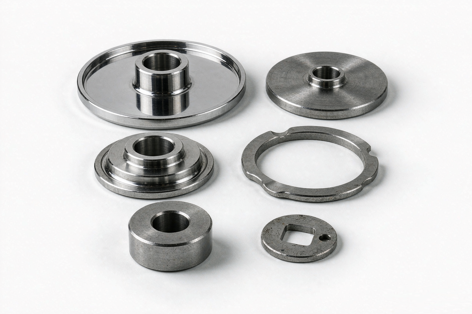
Cam Discs
Radial cams, plate cams, profile cams and custom contour cams machined from your profile data or drawing.
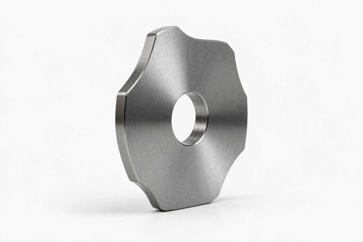
Cylindrical / Barrel Cams
Barrel, cylindrical and groove cams where the follower travels along a helical or contoured groove.
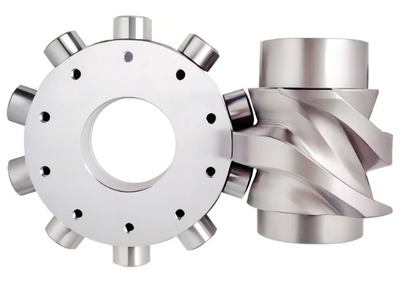
Camshafts
Custom camshafts and multi-lobe shafts with controlled lobe phasing and journal geometry.
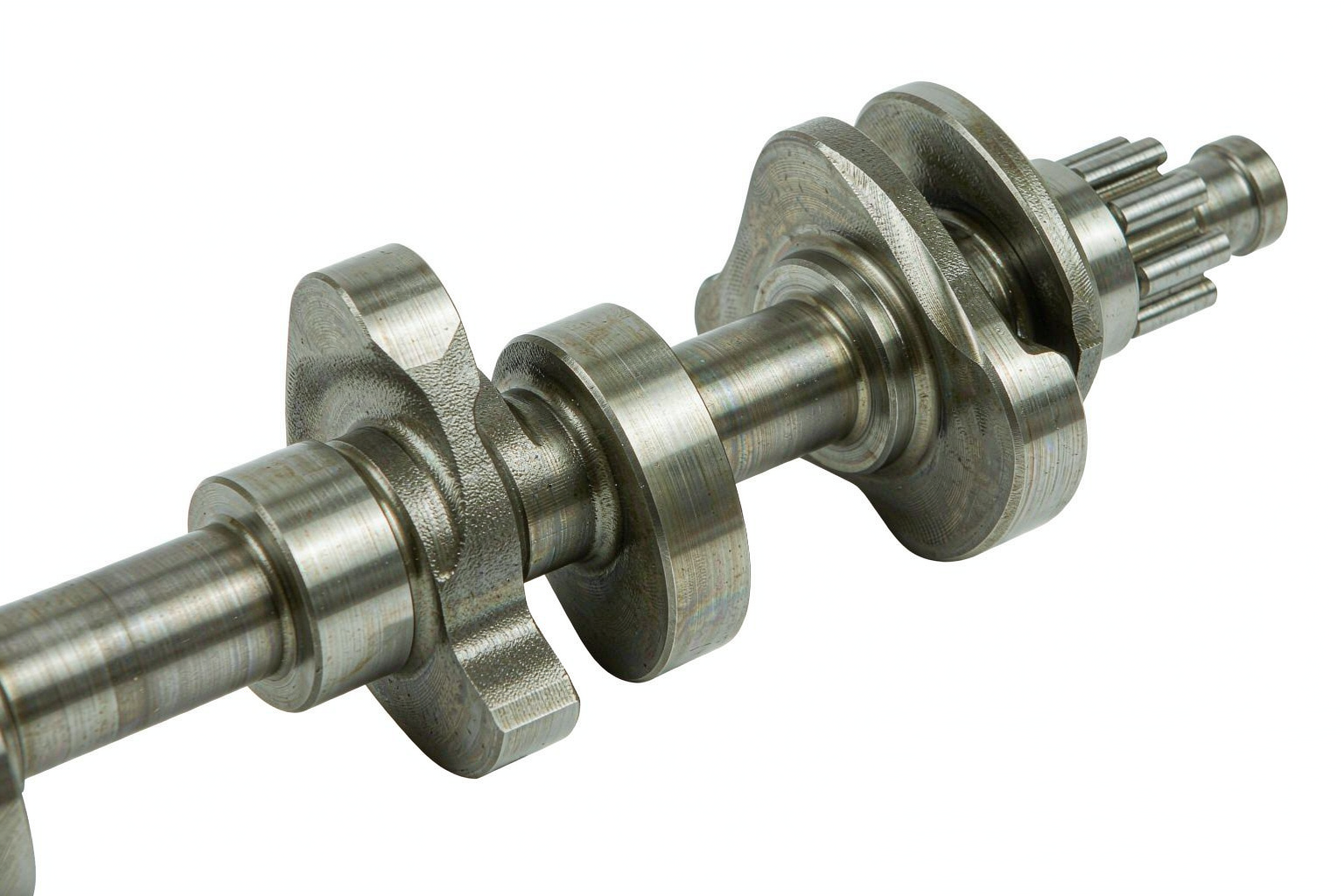
Rollers & Followers
Roller followers, cam rollers, guide rollers and track rollers in cylindrical, crowned, grooved and stud configurations.
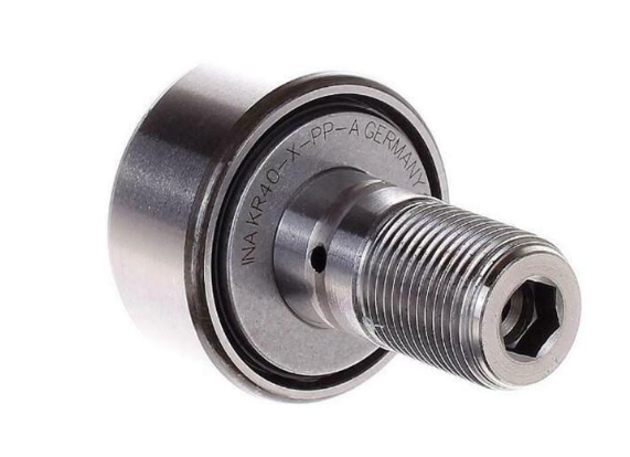
Matched Cam + Roller Assemblies
Cam and roller manufactured and verified as a matched set — mating geometry, clearance and runout reviewed together.
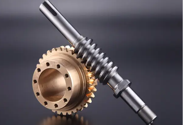
Not sure which category your part falls into? The table below maps each component type to the parameters that actually define it.
02Cam Component Types and Key Parameters
A cam is not one product. Each type is defined by a different set of dimensions — and those dimensions are exactly what a manufacturer needs to quote and inspect.
| Component | Main parameters |
|---|---|
| Cam disc | Profile, base circle, lift, pressure angle |
| Cylindrical / barrel cam | Groove profile, pitch, lead, follower diameter |
| Camshaft | Lobe profile, journal diameter, phase relationship between lobes |
| Roller follower | Roller OD, width, stud or bore, load, speed, seal type |
| Eccentric roller | Eccentricity, adjustment range, mounting interface |
| Cam + roller set | Profile, roller geometry, load, speed, alignment |
03What Information Is Needed to Manufacture a Custom Cam?
You do not need a complete drawing to start a conversation — but the more of the following you can provide, the faster the engineering review and the tighter the quote.
You can start three ways
- Option A — Complete drawing: manufacture to print, with DFM feedback on anything that affects cost or inspectability.
- Option B — 3D CAD model: we review the model and define manufacturing details together (datums, tolerances, heat treatment).
- Option C — Motion requirement only: give us lift, speed, cycle angle, dwell and load; our engineering team proposes the motion law, cam profile and roller selection.
Accepted input formats
- 2D drawings: DXF, DWG, PDF
- 3D models: STEP, IGES
- Motion data: CSV / Excel displacement-vs-angle tables
Specification checklist
- Cam type
- Base circle diameter
- Maximum lift
- Rise angle / return angle
- Dwell periods
- Motion law
- Pressure angle limit
- Roller diameter
- Follower offset
- Rotation speed
- Applied load
- Required life
- Material
- Heat treatment
- Surface finish
- Critical tolerances
04Cam Motion Profile & Motion Law
A cam is not machined “by its outline”. The outline is the result of a motion law applied through geometry. Understanding this chain is what separates a profiled disc from a functioning cam.
Every point on the cam surface encodes how the follower accelerates. Smooth acceleration and controlled jerk mean quieter, longer-lasting mechanisms; abrupt transitions concentrate stress at the contact point and show up later as wear, noise and vibration.
Common motion laws
Simple harmonic, cycloidal, constant acceleration/deceleration, 3-4-5 polynomial, modified sine — or a custom law from your own displacement table.
What we need from you
A stated motion law, an existing profile, or raw displacement data. If the law is unspecified, we flag it during the design review rather than guessing.
Why it matters for machining
The motion law determines curvature along the profile, which determines where finish grinding is needed and which features are measurable on a CMM.
05Pressure Angle: A Critical Cam Design Parameter
Pressure angle describes the angle between the follower motion direction and the force-transmission direction at the cam/roller contact point.
It directly controls how much of the transmitted force becomes side force on the follower. As pressure angle grows, side loading, friction, wear and required guide force all grow with it — which is why it is reviewed as a design constraint, not an afterthought.
Pressure angle is reviewed during design rather than fixed to one universal limit. Textbooks often target moderate values for translatable followers, but the appropriate value depends on follower type, speed, load, motion law and package constraints — so it is agreed per project.
06Cam Profile Curvature and Roller Diameter
Roller size and cam curvature are not independent choices.
If the roller radius is large relative to the local radius of curvature of the pitch curve, the profile self-intersects — a phenomenon called undercutting. The result: the produced cam cannot reproduce the intended follower motion, no matter how accurately it is machined.
Small roller + tight curvature
Higher contact stress and undercutting risk. The motion law may be unrealizable at the requested base circle size.
Larger roller + smoother curvature
Better contact conditions and lower stress, but a larger package and different motion characteristics. Roller and profile are selected together.
In practice this is one of the first things we check when a customer sends a profile: not “can we machine it”, but “will it produce the motion you expect”.
07Cam-to-Roller Contact: Where Wear Really Happens
All transmitted force passes through a small moving contact patch. Contact conditions — not brochure hardness numbers — determine how the pair behaves over time.
These eight factors interact. A harder surface with poor lubrication can fail faster than a moderate one properly greased; a larger roller at the same load reduces contact stress without changing material at all. This is why material selection is approached as a system decision in the next sections.
08How to Select a Roller or Cam Follower
Selection logic matters more than specification sheets. Six questions define the right follower for your mechanism.
Load
Radial, axial/thrust and shock loads. Shock loading changes hardness and clearance choices significantly.
Speed
Continuous speed, peak speed and acceleration. High speed shifts the trade-off toward precision profile and lubrication.
Track
Flat, grooved, curved or hardened track — and the mating surface condition of that track.
Alignment
Spherical (crowned) vs cylindrical roller, eccentric mounting for adjustment, and expected shaft/track misalignment.
Environment
Dust, coolant, corrosion, high temperature, washdown or clean-room conditions.
Maintenance
Sealed vs relubricatable, lubrication access, expected service interval.

09Spherical vs Cylindrical Roller Profiles
The outer-ring profile determines how the roller tolerates the real world — misalignment, edge loading and imperfect tracks.
| Profile | Typical advantage |
|---|---|
| Cylindrical | Broad contact on suitable tracks; efficient load carrying |
| Spherical / crowned | Tolerates angular misalignment and reduces edge-loading risk |
| Grooved | Guides against shaped tracks; resists lateral wandering |
| Custom profile | Matched to a specialized track geometry |
A crowned roller on a well-aligned track gives up some contact area; a cylindrical roller on a misaligned one concentrates stress at the edges. The right answer depends on your mechanism's alignment reality, not a general rule.
10Track and Mating Surface Requirements
The roller is only half of a rolling pair. The track it runs on is part of the system and must be specified as a purchase parameter — not left as a customer-side afterthought.
A soft track under a hardened roller wears quickly; a hardened track with coarse finish does the same to the roller. When you request a roller, telling us the mating track material and hardness lets us propose a hardness pairing that wears evenly instead of sacrificing one side.
11Materials & Heat Treatment Options
Materials are matched to function, not to a brochure. Common options and where they fit:
Bearing steel (GCr15 / 100Cr6 class)
High-carbon chromium steel selected for rolling-contact fatigue resistance and dimensional stability — the conventional choice for rollers and high-cycle cams.
Alloy steel (42CrMo / 4140 class)
Through-hardening alloy steel for heavily loaded shafts and structural cam bodies; frequently paired with surface hardening.
Stainless steel (304 / 316 / 316L)
Considered where corrosion resistance or washdown environments outweigh maximum hardness or wear performance — common in food and packaging machinery.
Tool / selected alloy steels
For selected high-wear or specialty hardened applications, subject to material availability and confirmed per project.

Heat treatment options
- Quenching & tempering
- Induction hardening
- Carburizing
- Nitriding
- Stress relieving
- Other verified treatments per project
Hardness, case depth and layer specifications are defined per material and process on the heat-treatment specification for your order — not published as universal product figures. Material certificates are available on request.
12How Heat Treatment Affects Cam & Roller Dimensions
Heat treatment changes geometry. Any process plan for a precision cam must account for it.
Quenching, carburizing and nitriding all cause dimensional change to some degree. For components with tight profile, runout or bore requirements, the process is sequenced so that critical surfaces are finish-machined or ground after heat treatment — which is why a high-precision cam is rarely a single-operation part.
This is also why quoting matters: two quotes for “the same” cam can differ simply because one plan grinds after heat treatment and the other does not.
13CNC Machining vs Precision Grinding for Cam & Roller Surfaces
Both are essential, and they are not interchangeable. The engineering question is: which features are CNC-machined and which require grinding?
CNC milling / turning
- Part geometry and general features
- Roughing and pre-heat-treatment stock
- Complex contours, hubs, keyways, mounting features
- Profile generation within general tolerance bands
Precision grinding
- Final diameters and bore sizes
- Roundness, cylindricity and runout-critical surfaces
- Surface finish on rolling-contact surfaces
- Hardened cam profiles and follower ODs after heat treatment
For turning-heavy geometries, see CNC turning services; for prismatic and multi-face profiles, see 5-axis CNC machining. Eccentric features are covered in our eccentric turning guide.
14Dimensional and Geometric Control
Precision on a cam is a set of specific, inspectable characteristics — not a single number.
Roller
- OD and width
- Roundness / cylindricity
- Runout
- Bore or stud concentricity
Cam
- Profile and base circle
- Phase angle (multi-lobe)
- Runout
- Bore concentricity
Assembly
- Cam axis ↔ roller axis alignment
- Profile ↔ track relationship
- Clearance / preload
Actual tolerance targets are established from the customer drawing and functional requirements. As general CNC capability, typical tolerances are ±0.01 mm with tighter targets around ±0.005 mm on qualified features; published universal figures for every cam would not be meaningful.
15Lubrication, Sealing & Contamination Control
Lubrication and sealing decisions belong in the specification stage because they constrain design choices — seal geometry, groove features, surface finish and material coatings all interact with them.
Tell us
Lubricant type, relubrication interval, operating temperature, contamination exposure (dust, coolant, washdown) and whether the design is sealed or open.
Design responses
Sealed or shielded configurations, relubricatable features, groove and lip geometry, and surface finish tuned to retain or shed lubricant.
Why early
Retrofitting a sealing solution after machining usually means redesign; specifying it upfront costs nothing extra.
16Common Cam & Roller Failure Modes
Engineers rarely search for “cam parts” when something breaks — they search for the symptom. Each failure mode below points to specific parameters to review.
| Failure | Possible cause | What to review |
|---|---|---|
| Pitting | Contact fatigue | Load, material, hardness, lubrication |
| Spalling | Fatigue / overload | Contact stress, load spectrum |
| Scuffing | Poor lubrication / sliding | Lubrication, speed, surface finish |
| Excessive wear | Abrasive environment | Material, hardness, sealing |
| Edge loading | Misalignment | Roller profile, track alignment |
| High vibration | Profile error / balance / runout | Geometry, inspection records |
| Backlash | Poor fit / wear | Functional interfaces, clearance |
| Noise | Surface / profile / lubrication | Finish, profile accuracy, preload |
If you are troubleshooting an existing mechanism, send the failed part and its operating context — the failure surface often identifies the root cause faster than any description.
17From Motion Requirement to Finished Component
Cam design and cam manufacturing are different steps. Our role is to convert your motion requirement into a manufacturable, inspectable component.
18Prototype and Production Cam & Roller Components
Cam components are rarely one-shot standard parts. A staged approach protects both sides.
Prototype orders start from 1 piece (MOQ 1 piece for prototypes). Typical lead times: 3–7 working days for prototypes, 7–20 for low-volume batches, 15–25 for production runs — confirmed per project, since heat treatment and grinding scope affect the schedule.
19Typical Cam & Roller Applications
Described by mechanical function rather than by industry label — because that is how the parts are actually specified.
Indexing mechanisms
Rotary indexing tables and transfer mechanisms driven by profiled cams and matched followers.
Packaging machinery
Cam-driven stations, pick-and-place mechanisms and feeding systems with repetitive synchronized motion.
Automation equipment
Linear motion, actuation and positioning mechanisms where a mechanical motion law is preferred.
Machine tools
Tool changers, pallet changers and cam-driven auxiliary mechanisms.

20What Determines Cam & Roller Component Cost?
Honest cost drivers, in the order they usually matter:
A simple cam profile can be inexpensive to machine. A precision profile requiring heat treatment, grinding and profile verification can carry a substantially different cost at the same overall size — because the cost lives in the process chain, not in the metal. Quoting separates these drivers explicitly so you can see where the money goes and decide which requirements actually matter.
21Quality & Inspection for Cam and Roller Components
Inspection is planned around the characteristics that make the part function.
Cam inspection
- Profile accuracy
- Lift
- Phase angle
- Runout
- Bore size & concentricity
- Surface finish
Roller inspection
- OD / ID / stud diameter
- Roundness / cylindricity
- Runout
- Width
- Surface finish
Assembly checks
- Matching geometry
- Rotation smoothness
- Clearance / preload
- Functional movement
Standards and customer specifications
Manufacturing standards are selected according to the customer's drawing, material specification, inspection plan and application requirements. Applicable documents may include material standards, heat-treatment specifications, surface-treatment specifications, customer drawing GD&T and inspection standards. Dimensional inspection reports, material certificates and heat-treatment records are available on request; RoHS and SGS test reports can be provided. Production is performed under an ISO 9001:2015 certified quality system.
22Representative Engineering Example
The following is an illustrative example of how a cam requirement is turned into a specification — it describes the engineering workflow, not a specific client project.
- Part
- Custom indexing cam disc
- Application
- Packaging machine indexing station
- Input
- Displacement-vs-angle table (CSV)
- Engineering
- Motion law confirmed; pressure angle and curvature checked; roller matched to profile
- Material
- Bearing steel, through-hardened
- Machining
- CNC milling of profile + grinding of functional surfaces after heat treatment
- Critical requirement
- Profile accuracy + phase angle + runout on bore
- Inspection
- Profile check, runout, bore measurement; report with shipment
Have a comparable requirement?
23Custom Cam & Roller RFQ Checklist
Copy this checklist into your request, tick what you know, and leave the rest blank — we will ask about anything missing before quoting.
Part type
- Cam
- Camshaft
- Roller
- Cam follower
- Cam + roller assembly
Motion
- Lift / stroke
- Rotation angle
- Speed
- Dwell
- Motion law
Load
- Radial load
- Axial load
- Shock load
- Required service life
Geometry
- Cam profile
- Roller diameter
- Roller width
- Bore / stud
- Eccentricity
- Track geometry
Material
- Steel grade
- Stainless steel
- Bearing steel
- Other
Heat treatment
- Through hardening
- Induction
- Carburizing
- Nitriding
- Other
Finish
- Grinding
- Polishing
- Coating
- Surface treatment
Inspection
- Profile
- Diameter
- Roundness
- Runout
- CMM report
- Functional test
24Frequently Asked Questions
What is a cam follower and how is it different from a cam?
A cam is the profiled driver converting rotary motion into a prescribed follower motion; a cam follower (roller follower) is the rolling component riding on the cam surface or track. We manufacture cams, camshafts, rollers and followers to drawing — and matched sets where required.
What information is needed to manufacture a custom cam?
Cam type, base circle, lift, rise/return/dwell angles, motion law, pressure angle limits, roller diameter, speed, load, material, heat treatment and critical tolerances. A drawing, CAD model or displacement table can all be starting points.
Can you manufacture a cam from a motion or displacement table instead of a drawing?
Yes. A CSV or Excel angle-displacement table can be converted into a cam profile; we confirm the motion law, pressure angle and curvature checks with you before machining.
What is pressure angle and why does it matter?
It is the angle between follower motion direction and force-transmission direction at the contact point. Larger pressure angles raise side force, friction, wear and required guide force. It is reviewed per project, not fixed to one universal limit.
How does roller diameter affect cam profile design?
The roller radius must stay below the minimum radius of curvature of the pitch curve, or undercutting occurs and the produced cam cannot reproduce the intended motion. Roller diameter and profile geometry are selected together.
Cylindrical or spherical (crowned) roller follower — which one?
Cylindrical offers broad contact and efficient load carrying on well-aligned tracks; crowned tolerates misalignment and reduces edge loading; grooved guides against shaped tracks. The choice depends on your alignment reality.
What causes cam follower wear and failure?
Common modes: pitting and spalling (contact fatigue), scuffing (lubrication), abrasive wear (contamination), edge loading (misalignment), vibration and noise (profile error or runout). Each mode points to specific parameters to review — see the failure-mode table above.
When should a cam or roller be ground after heat treatment?
Whenever roundness, cylindricity, profile accuracy or finish requirements would be compromised by heat-treatment distortion. Typical candidates: roller OD and bore, camshaft journals, and hardened cam profile surfaces.
What tolerances can be held on custom cam components?
Typical CNC tolerances are ±0.01 mm, with tighter targets around ±0.005 mm on qualified features. Actual targets come from your drawing and functional requirements.
What is the MOQ and lead time?
Prototypes from 1 piece; typical lead times 3–7 working days (prototype), 7–20 (low volume), 15–25 (production) — confirmed per project since heat treatment and grinding affect schedule.
Do you provide material certificates and inspection reports?
Yes — material certificates, heat-treatment records and dimensional inspection reports are available on request, and RoHS/SGS test reports can be provided. Production runs under an ISO 9001:2015 certified quality system.
Can you supply matched cam and roller assemblies?
Yes. Cam and roller can be manufactured and verified as a matched set, with mating geometry, clearance and runout reviewed at assembly.
Request a Cam & Roller Review
Send a drawing, a CAD model, or simply describe the motion you need. Our engineering team responds with a manufacturability review and quote within 24 hours.
Xiamen Goldcattle Plastic & Metal Products Co., Ltd. · Founded in 1998 · 100+ machines across six processes · ISO 9001:2015 certified