Eccentric Turning CNC: Principles, Methods & Applications
Your part has a journal, pin, or cam whose axis sits off the shaft centerline. That offset is not a tolerance slip — it is the function. Eccentric turning machines that feature about its own displaced axis so the diameter runs true to the offset, not to the spindle. We set the offset by fixturing and index, then hold runout by fixture repeatability and measurement.
Two axes, one part: the offset e defines the eccentricity.
What Is Eccentric Turning?
Eccentric turning is the machining of a diameter, cam, or pin whose center axis is deliberately displaced from the workpiece's main spindle axis by a distance e. Where ordinary (concentric) turning keeps every feature on one axis, eccentric turning places selected features on a second, parallel axis. The result is a part in which one section rotates off-center — exactly what a crankshaft journal, an offset pivot, or a pump cam needs to do its job. The offset is a designed dimension, controlled like any other, not a defect.
The Eccentricity Geometry: e, θ, and Runout (TIR)
The geometry is defined by three values. e is the radial distance between the main axis and the eccentric axis. θ is the angular reference that fixes where the eccentric axis sits relative to a datum feature on the part. Runout, read as total indicator reading (TIR), equals 2e plus any roundness or form error in the offset diameter. Holding a tight runout therefore means holding e tightly and keeping the offset feature round. The diagram below shows how a small e produces a large, deliberate sweep at the offset diameter.
How the Eccentric Axis Is Established
The machine always turns about the axis it is given. To turn about the eccentric axis, the workpiece datum must be relocated. The common ways are: a second, off-center hole or bushing in the fixture; a soft jaw bored off-center to the required e; an eccentric collet; or an indexed fourth-axis (C-axis) rotation that presents the feature at a controlled angle. Each method fixes the same thing — the turning axis moves from O to O′ by exactly e. The choice depends on whether the feature is a full revolution (turn it) or a partial form (index or mill it).
Off-Center Workholding Methods
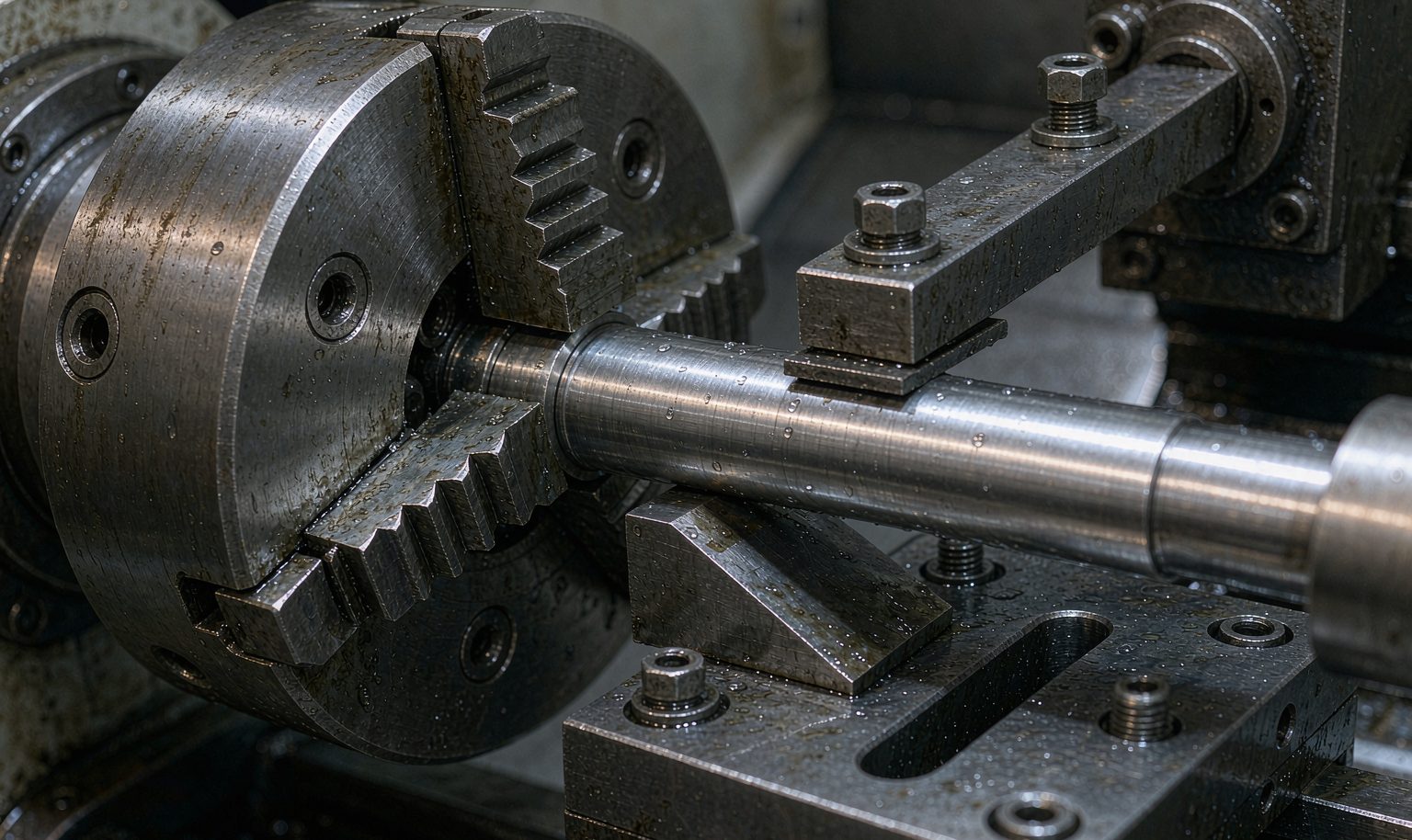
Most eccentric shafts are held by one of four setups. A bored-offset soft jaw is quick for low volumes and re-bored per job. An eccentric fixture plate with a precision bushing gives the best repeatability across a batch because every part seats on the same offset center. An eccentric collet suits small diameters and bar feed. An indexed chuck or fourth axis is used when several eccentric features sit at different angles around the part. The bushing approach wins on consistency; the jaw approach wins on setup speed.
C-Axis Synchronization vs Off-Center Fixturing
These are not rivals — they cover different feature shapes. Off-center fixturing is for full-revolution eccentric diameters: you seat the part on the offset axis and turn it like any shaft. C-axis synchronization or live tooling is for partial features — a flat, keyway, or cam lobe that exists over only part of the rotation and must be cut at a fixed angular position. If the eccentric feature is a complete circle, fixturing is simpler and cheaper. If it is an arc or a milled face, you need angular control. The decision tree below separates them by feature type.
CNC Methods for Eccentric Features
On the floor, eccentric features are produced three ways. A two-operation offset turns the main diameters, then re-chucks the part on the offset axis to turn the eccentric diameter. An indexed fourth-axis setup holds the part once and rotates to each eccentric position, good for multi-angle features. A mill-turn with C-axis turns the shaft and mills partial eccentric forms in one clamping, protecting concentricity between features. Two-operation is cheapest for one offset; single-clamp mill-turn is best when several eccentric features must stay in position relative to each other.
Eccentric Turning vs Standard (Concentric) Turning
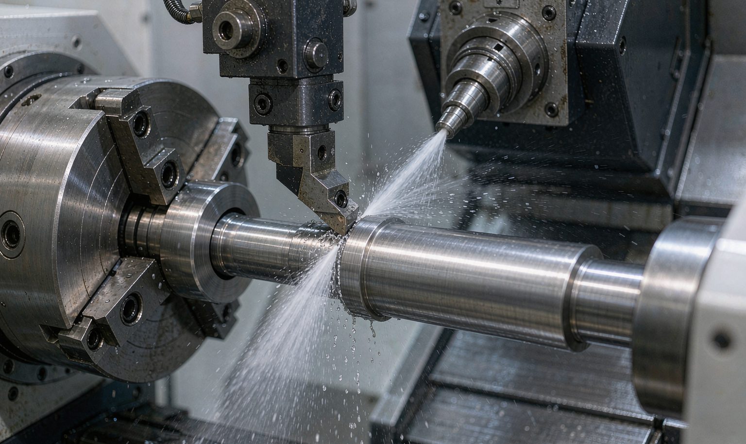
Standard turning assumes one axis for the whole part; the lathe, chuck, and steady rest all reference it. Eccentric turning adds a second reference that must be re-established for the offset feature, which is why it needs a deliberate fixture or index rather than just a different toolpath. The payoff is function: an eccentric journal converts rotation into stroke, an offset pin sets a linkage geometry, a cam lobe defines a lift profile. Treat eccentric turning as a datum problem first and a cutting problem second — get the axis relocation right and the cut is ordinary.
Tolerance Chain and Datum Control
Runout at the eccentric diameter is the sum of every link in the datum chain: the fixture bore offset, the seating repeatability, the chuck index, and the part's own roundness. Tightening the final tolerance by tightening only the lathe setting misses the real driver. We control the chain at the source — a ground offset bushing, an indicated seating, a defined clamp force — then verify the link that matters to the customer: TIR at the offset diameter. Calling out the datum and its angular reference on the drawing keeps the whole chain unambiguous.
Eccentricity Control and Alignment
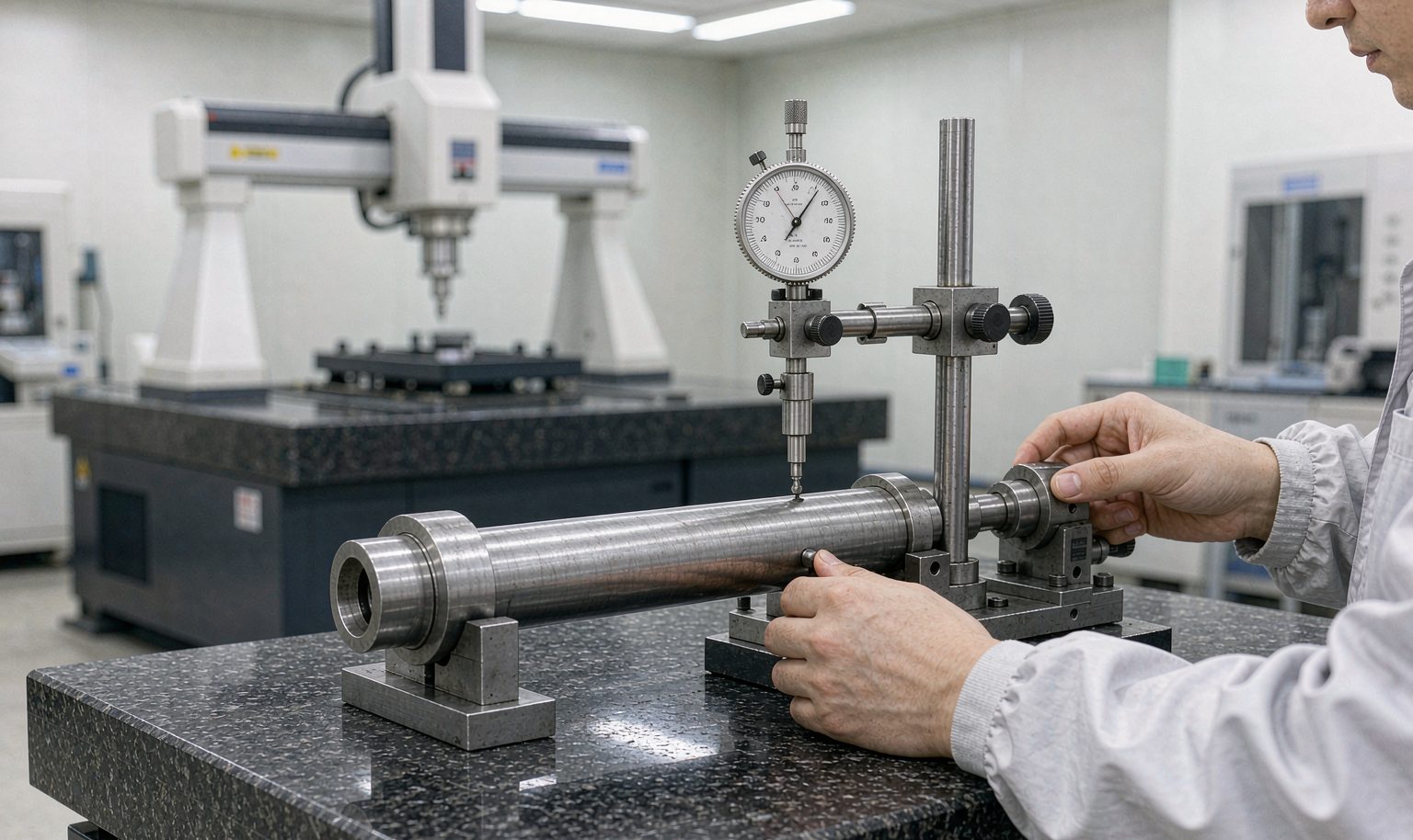
Before the first cut, the offset is indicated with a dial test indicator so the bushing or jaw center sits at the target e from the spindle axis. Clamp force is set to avoid shifting the datum, and the part is supported so it cannot deflect into the cut. Across a batch, repeatability comes from the bushing, not from re-indicating each piece. Where several eccentric features share one part, a single indexed chuck keeps their angular relationship fixed instead of relying on separate setups that can drift.
Runout and Concentricity Inspection
The offset diameter is checked by rotating the part on its main axis and reading runout with a dial indicator or TIR gauge; the sweep is 2e. For full verification, a CMM probes both axes and reconstructs e and the angular position θ directly, which is how we confirm the feature sits where the drawing says. First articles are measured before any production run, and the offset bushing is checked so batch repeatability is proven, not assumed. Sampling continues through the run against the called-out runout limit.
Typical Eccentric Parts
Eccentric turning shows up wherever rotation must become offset motion. Crankshaft journals and eccentric shafts convert spin into stroke. Camshaft lobes and pump or compressor eccentrics drive followers and plungers. Offset pivot and linkage pins set a mechanism's geometry. Rocker and actuating shafts carry a feature that must sit at a fixed angle to the rest of the part. If your drawing has one diameter that is intentionally not coaxial with the others, it is an eccentric feature and the methods above apply directly.
Materials for Eccentric Turned Parts
Any turned material takes an eccentric feature. Carbon and alloy steels are routine for shafts and cranks. Stainless steel is common in food, medical, and marine parts where the offset must resist corrosion. Aluminum and brass suit lighter linkages and fittings. Engineering plastics are used where weight or insulation matters. Hardened parts are turned near-size and then ground to the offset diameter, because grinding holds e more reliably than turning alone. Material choice drives the fixture wear surface and the finish method more than the eccentric geometry itself. For stainless specifics, see our stainless steel CNC machining program.
Surface Finish and Dimensional Stability
Eccentric diameters often sit in bearing or contact zones, so finish and stability matter. Turning sets the size; grinding or fine turning reaches the surface and the tight e together when the feature is hardened. Heat treatment before finish grinding avoids moving the offset as the part relieves stress. Where the eccentric diameter is a wear surface, we match the finish to the application and confirm it on the first article. Stability is a fixture and process question first — a shifting datum defeats any surface spec.
Four Sources of Eccentric Error
| Error source | What it does | How we control it |
|---|---|---|
| Fixture bore offset | Sets the wrong e | Ground bushing to drawing, CMM-checked |
| Chuck / index error | Shifts angular position θ | Indicated seating, single indexed chuck |
| Clamp distortion | Moves datum under load | Defined clamp force, support |
| Thermal growth | Drifts e during the cut | Stable setup, measure first article |
Design Rules for Eccentric Features
- Call out e from the main axis and the angular reference (θ) the eccentric axis is measured from.
- Specify the offset diameter and its tolerance, plus the allowed runout (TIR) at that diameter.
- State whether the feature is a full revolution (turn) or a partial arc (needs C-axis / milling).
- Avoid stacking two tight offsets on one part unless a single indexed chuck can hold their relationship.
- Note any post-heat-treatment grind so the offset is finished after stress relief.
Prototyping to Production
Eccentric parts move from prototype to production on the same fixture logic, just at different volumes. A prototype can use a bored soft jaw for speed; a production run uses a ground offset bushing for repeatability across the batch. Lead time follows the usual bands — prototype in 3 to 7 working days, low-volume in 7 to 20, series production in 15 to 25 — with the fixture design confirmed at the quote stage. MOQ is one piece for prototypes, so you can verify e and runout before committing to volume.
Our Eccentric Machining Capability
The methods above describe how eccentric features are established and controlled in general CNC practice. The note below states what Xiamen Goldcattle Plastic & Metal Products Co., Ltd. quotes against your drawing.
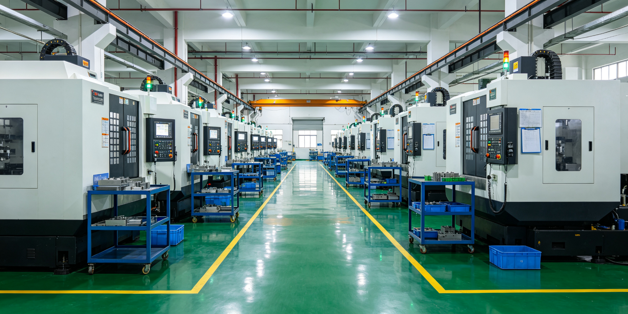
We machine eccentric and offset features using off-center workholding and indexed setups on our CNC turning and mill-turn platforms, performed in-house under one ISO 9001:2015 quality system. For full-revolution eccentric diameters this is a standard turning operation; we hold the offset by fixture repeatability and confirm it by first-article and CMM inspection. Features that require a synchronized C-axis or live-tool milling at a controlled angle are evaluated per project against the available equipment — send the model and we confirm the method and the achievable e before quoting. Typical turning tolerance is ±0.01 mm, with ±0.005 mm on qualified features called out on the drawing.
Case Study
The example below is a representative project type. Figures illustrate a typical eccentric shaft program and are not tied to a named customer.
An eccentric shaft needed two offset journals at a fixed angular relationship for a pump drivetrain. A two-operation re-chuck risked losing the angle between journals, so we held the part in a single indexed chuck and turned both eccentric diameters in one clamping. Material was 17-4 PH stainless, turned near-size and finish-ground to the offset diameters. Result: e held to drawing across the batch, angular relationship preserved, and runout verified on the CMM at first article before release. Programs like this are routine for pump, compressor, and linkage shafts with intentional offsets.
Frequently Asked Questions
The structured Q&A above covers the twelve questions buyers ask most: what eccentric turning is, how the axis is established, the e-to-runout relationship, fixturing versus C-axis choice, achievable offset, error sources, inspection, materials, and how to call the feature out on a drawing. If your part raises a question not covered there, send the model and we will answer it in the review.
Request an Eccentric Machining Review
Send your 3D model and the called-out offset e, angular reference, and runout limit. We return a fixture-or-C-axis method, the achievable offset for your material, and a dated prototype-to-production plan — under one ISO 9001:2015 quality system at Xiamen Goldcattle Plastic & Metal Products Co., Ltd.