Can a CNC Supplier Hold ±0.01 / ±0.005 mm Tolerance?
A direct, engineer-to-engineer answer for buyers who need to know whether their drawings can be held, verified, and repeated in production — not a generic tolerance blog post.
Yes — a qualified CNC supplier can achieve ±0.01 mm on selected features, and ±0.005 mm can be achieved for certain dimensions under controlled machining and inspection. Neither should be treated as a universal tolerance for every CNC-machined feature.
Tolerance feasibility at a glance
| Tolerance | Difficulty | Usually requires |
|---|---|---|
| ±0.05 mm | Standard | Controlled CNC process |
| ±0.02 mm | Precision | Stable machine + process control |
| ±0.01 mm | High precision | Tight process control + inspection |
| ±0.005 mm | Ultra precision | Specialized machining + thermal/process control + verification |
Jump to your question
This page is organized as the questions a procurement engineer actually asks when qualifying a tight-tolerance supplier. Pick the one you are deciding on.
1Quick Answer: Can CNC Machining Hold ±0.01 / ±0.005 mm?
If you only have 30 seconds, here is the engineer’s summary. The rest of the page explains each line.
2What Do ±0.01 mm and ±0.005 mm Tolerances Mean?
A tolerance defines the acceptable deviation from a nominal dimension. It is not the machine’s accuracy number — it is the band your finished part must fall inside.
Worked example on a Ø20.000 mm bore
| Drawing callout | Low limit | High limit | Total window |
|---|---|---|---|
| Ø20.000 ±0.005 mm | 19.995 mm | 20.005 mm | 0.010 mm |
| Ø20.000 ±0.010 mm | 19.990 mm | 20.010 mm | 0.020 mm |
| Ø20.000 ±0.020 mm | 19.980 mm | 20.020 mm | 0.040 mm |
| Ø20.000 ±0.050 mm | 19.950 mm | 20.050 mm | 0.100 mm |
The most important distinction on this page: machine accuracy (how precisely the axis can position) is not the same as finished-part dimensional tolerance (what the measured part actually is). A CNC machine’s positioning specification does not automatically mean the finished part can hold the same dimensional tolerance — the result is the sum of machine condition, fixturing, tooling, material behavior, thermal state and measurement error.
3Can CNC Machining Really Hold ±0.01 mm?
Yes — but the answer depends on the feature.
±0.01 mm is a well-established high-precision band for CNC machining. It is routinely held on the right features with process control and inspection. The catch is that “the part is ±0.01 mm” is meaningless until you say which dimension. Below is how capability typically breaks down by feature type.
Hole diameter
Precision bores are among the most controllable features.
- Precision-bored holes
- Reamed holes after drilling
- Bearing bores and shaft seats
- Locating bores with reaming/finishing pass
Shaft diameter
Rotating and slip-fit diameters are natural candidates.
- Precision shafts and spindles
- Bearing journals
- Rotary and valve components
- Turned OD with single-setup control
Linear dimensions
Block-type and prismatic dimensions can be held tightly.
- 20.000 ±0.010 mm stepped lengths
- 50.000 ±0.010 mm slide widths
- Thickness and step heights
Hole-to-hole position
This is where buyers most often confuse two different things.
- Dimensional tolerance ≠ positional tolerance
- A ±0.005 mm size does not imply ±0.005 mm position
- Position, concentricity and perpendicularity are separate controls
4Can CNC Machining Hold ±0.005 mm Tolerance?
±0.005 mm (5 microns) is a demanding tolerance and should be treated as a feature-specific precision requirement rather than a general CNC machining tolerance. Achieving it repeatedly is the output of seven controlled variables working together — not one of them alone.
What is required to achieve ±0.005 mm
Machine accuracy
Axis positioning and repeatability, machine age, rigidity and current calibration state. A worn or untuned machine cannot deliver tight results regardless of program.
Thermal stability
Temperature changes move the machine, the workpiece, the tool and the measurement. Spindle warm-up, ambient control and measuring after stabilization matter.
Tooling
Tool wear, runout, length compensation and edge condition all shift size. Tool management and in-process compensation are part of the tolerance, not an afterthought.
Workholding
Clamp force, fixturing deformation and re-clamping error introduce variation. One-setup strategies reduce cumulative error.
Machining strategy
Roughing, semi-finishing, finishing, spring passes, single setup and multi-axis access all influence residual stress and final size stability.
Material
Aluminum, steel, stainless, titanium, copper and plastics respond completely differently. Thermal expansion and residual stress behave per material.
Inspection
The tolerance is only proven when measured on appropriate metrology. Capability without verified measurement is an unverified claim.
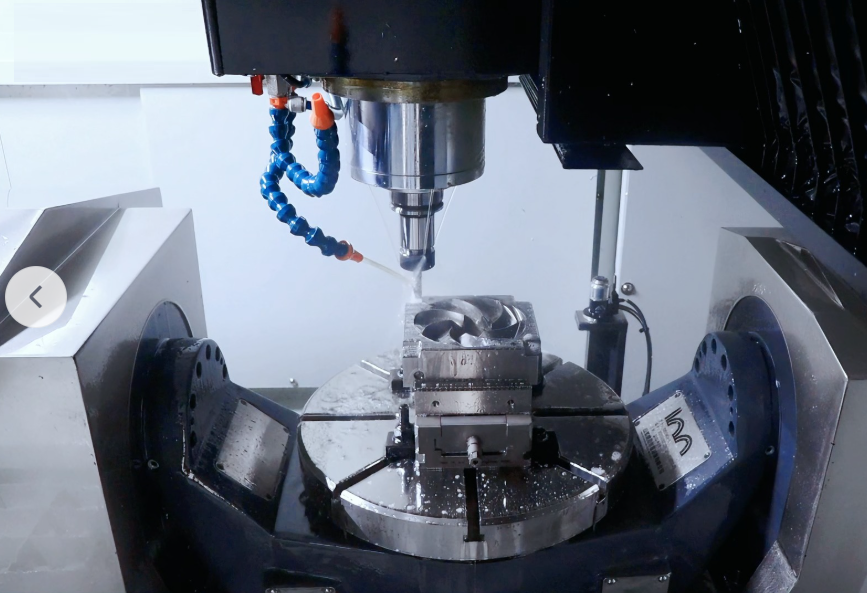
5What Affects Whether You Actually Get ±0.01 / ±0.005 mm?
The same feature can be easy on one part and impossible on another. This table shows how strongly each factor influences the two tolerance bands — useful when you review a supplier’s capability claim.
| Factor | Impact on ±0.01 mm | Impact on ±0.005 mm |
|---|---|---|
| Machine condition | High | Very High |
| Temperature | Medium | Very High |
| Tool wear | High | Very High |
| Workholding | High | Very High |
| Material stability | Medium | High |
| Setup changes | High | Very High |
| Cutting strategy | High | Very High |
| Inspection method | High | Critical |
Notice that inspection method moves from “High” to “Critical” at ±0.005 mm. Below about 10 microns, how you measure becomes as important as how you cut — a caliper that reads to 0.01 mm cannot verify a 0.005 mm requirement.
6Which Materials Can Be Machined to ±0.01 / ±0.005 mm?
Material behavior under cutting force, heat and time is a major driver of achievable tolerance. The table reflects typical practice, not a universal guarantee — every grade and feature still needs review.
| Material | ±0.01 mm | ±0.005 mm | Main considerations |
|---|---|---|---|
| Aluminum 6061 | Yes | Yes* | Thermal expansion, thin walls |
| Aluminum 7075 | Yes | Yes* | Stability and tool control |
| Stainless Steel 316L | Yes | Limited | Work hardening, heat |
| Tool Steel | Yes | Yes* | Stable finishing process |
| Titanium | Yes | Limited | Heat and tool wear |
| Brass | Yes | Yes* | Good machinability |
| PEEK | Limited | Limited | Thermal expansion, deformation |
| ABS / PC | Limited | No | Material deformation |
Yes* means achievable on selected features with appropriate process control and inspection — not that every shape of that material can hit ±0.005 mm. Limited means only specific, well-controlled features may reach the band; No means it should not be specified as a general requirement.
7CNC Milling vs CNC Turning for ±0.01 / ±0.005 mm
Neither process is “more accurate” in the abstract — each owns a class of features. Match the process to the geometry.
| Process | Best for | Tight-tolerance examples |
|---|---|---|
| CNC Turning | Shafts, bores, cylindrical features | Diameter, concentricity, runout |
| CNC Milling | Prismatic components | Length, width, hole location |
| 5-Axis CNC | Complex multi-surface geometry | Complex datum relationships |
| Grinding | Extremely tight features | Final-size finishing |
| Reaming | Precision holes | Hole diameter |
| Honing | Precision bores | Bore geometry |
| Wire EDM | Complex hard-material profiles | Fine profiles |
8When CNC Machining Is Not Enough for ±0.005 mm
Not every ±0.005 mm requirement should be forced through standard CNC milling or turning. A competent supplier recommends the right secondary process instead of simply promising a tighter CNC tolerance.
Reaming
Refines a drilled hole to a precise diameter with excellent bore finish — a common first step before any exotic process.
Grinding
Delivers extremely tight size and surface quality on hardened or difficult features that cutting cannot reach.
Honing
Corrects bore geometry — roundness, taper and straightness — for precision internal diameters.
Wire EDM
Cuts complex profiles in hardened materials where tool access or heat would defeat CNC milling.
9How Do You Verify ±0.01 / ±0.005 mm CNC Tolerances?
A tolerance is only real once it is measured with equipment whose resolution and accuracy suit the band. Calipers are excellent tools — but not for verifying a 5-micron critical feature.
Calipers
Fast shop-floor checks for general dimensions.
Not for ±0.005 mm critical featuresMicrometer
Suitable for many external diameters and thicknesses.
Partial coverage of ±0.005 mmBore gauge
Measures precision internal diameters and bore size.
Good for boresHeight gauge
Checks step heights, positions and perpendicularity on a reference.
Position / heightCMM
The reference method for complex size, position and full GD&T.
Recommended for ±0.005 mmOptical / vision
Non-contact measurement of small, complex or hard-to-reach geometry.
Micro / complex features10CMM Inspection and Measurement Reports
This is what verification looks like in practice: the drawing defines the requirement, the part is machined, and the CMM reports the measured result against the datums. (Figures below are representative of the workflow; measured values must come from your actual part and live inspection.)
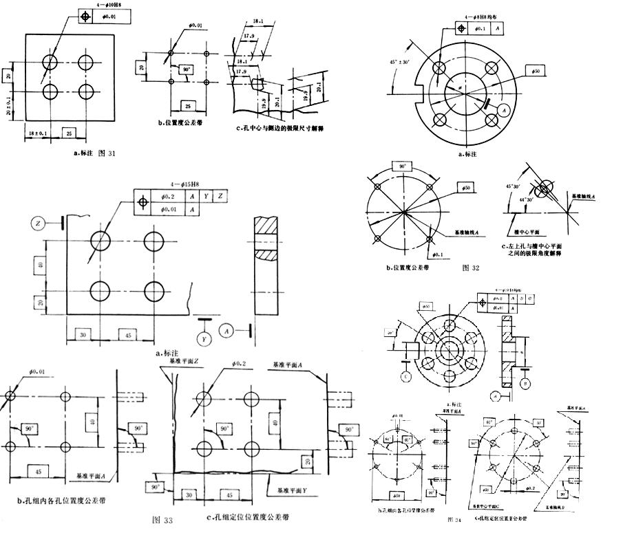
1 · Drawing requirement
Ø25.000 ±0.005 mm bore with position and datum references defined by GD&T.
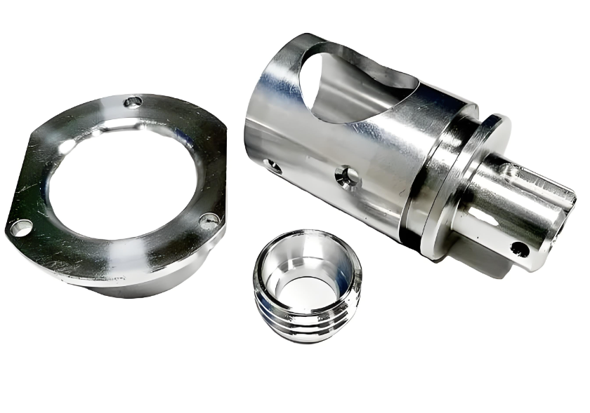
2 · CNC part
Machined in a controlled setup, allowed to stabilize before final inspection.
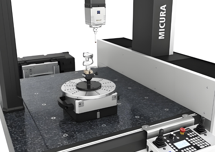
3 · CMM report
Programmed probe measures the feature; results are reported against the drawing.
Example measured result (representative)
| Measurement point | Requirement | Actual (mm) | Status |
|---|---|---|---|
| 1 | 24.995 – 25.005 | 25.002 | In |
| 2 | 24.995 – 25.005 | 25.001 | In |
| 3 | 24.995 – 25.005 | 24.999 | In |
| 4 | 24.995 – 25.005 | 25.003 | In |
| 5 | 24.995 – 25.005 | 25.001 | In |
A real report also includes the datum structure, probe path, environment note and calibration status. Treat any tolerance claim without a corresponding measurement as unverified.
Need proof instead of a tolerance claim? Request a CMM inspection review with your RFQ →11Does a Tighter Tolerance Increase CNC Machining Cost?
Yes — but the increase is not a flat multiplier. It comes from the extra work each tighter band requires. The ladder below shows the typical cost direction.
The cost at ±0.005 mm is driven by: additional setups, slower cutting parameters, finishing and spring passes, tool replacement, temperature control, inspection and CMM programming, and increased rejection risk. The cheapest ±0.005 mm part is usually the one that did not need ±0.005 mm in the first place.
12Is ±0.005 mm Really Necessary for Your CNC Part?
The tightest possible tolerance is not always the best manufacturing tolerance. Over-specifying quietly adds cost and risk without improving function.
Example
If a design is called out at 50.00 ±0.005 mm but the function only needs 50.00 ±0.02 mm, the tighter callout adds machining time, inspection time, scrap risk, tooling and setup requirements, and production cost — for no functional gain.
This is also where a good supplier earns the project: by reviewing the print and telling you which dimensions must be tight and which can be relaxed — reducing cost before the first chip is cut.
13How to Evaluate a CNC Supplier’s ±0.005 mm Capability
Use this checklist when qualifying a supplier for tight-tolerance work. The right answers reveal whether they understand the difference between a machine spec and a finished-part capability.
| Question to ask | Why it matters |
|---|---|
| What is your achievable tolerance on this material? | Capability varies by material — a real answer is specific. |
| Is ±0.005 mm guaranteed on all features? | Filters out misleading blanket claims. |
| Which dimensions can you actually hold? | Confirms feature-specific thinking. |
| What inspection equipment do you use? | Measurement credibility is part of the capability. |
| Can you provide CMM reports? | Verification — proof instead of a claim. |
| Can you provide FAI? | First-article validation before production. |
| What GD&T standard do you follow? | Correct drawing interpretation of geometric controls. |
| Can you control temperature? | Thermal stability at ±0.005 mm is essential. |
| Can you perform grinding / honing / EDM? | Access to secondary precision processes when CNC is not enough. |
14Xiamen Goldcattle Precision CNC Machining Capability
Goldcattle is a China-based OEM/ODM manufacturer (Founded in 1998) producing custom CNC machined metal and plastic parts from prototype through production. For tight-tolerance projects we review the drawing first and quote by feature — not with a single headline number.
CNC equipment
- 3-, 4- and 5-axis machining centers
- CNC turning and turn-mill centers
- Swiss-type lathes for slender parts
- Part of 100+ machines across six processes
Materials
- Aluminum (6061, 7075, etc.)
- Stainless & carbon steel, tool steel
- Brass, copper, titanium
- Engineering plastics & PEEK
Precision capability
- High precision to ±0.01 mm on selected features
- Ultra precision to ±0.005 mm on selected features
- Surface finish down to Ra 0.4 µm under review
- CMM, bore gauge, micrometer, height gauge, vision
Our precision CNC capability range
*Subject to part geometry, material, size, feature location, machining process and inspection requirements. We state capability by feature after reviewing your drawing — not as a universal tolerance for every dimension.
Content reviewed by Goldcattle Manufacturing & Quality Engineering. Exact machine models, calibration certificates and live counts are provided during a supplier audit or on request.
15Frequently Asked Questions
Can CNC machining achieve ±0.01 mm?
Can CNC machining achieve ±0.005 mm?
Is ±0.005 mm realistic for aluminum CNC machining?
What CNC machine is required for ±0.005 mm tolerance?
Can a 5-axis CNC machine hold ±0.005 mm?
What is the difference between ±0.01 mm and ±0.005 mm?
Do I need CMM inspection for ±0.005 mm parts?
Is ±0.005 mm more expensive than ±0.01 mm?
Can CNC turning hold ±0.005 mm on shaft diameters?
When should I use grinding instead of CNC machining?
Can Goldcattle inspect critical dimensions using CMM?
Need ±0.01 or ±0.005 mm CNC Parts?
Send your drawing and we will review manufacturability, tell you which dimensions truly need to be tight, and quote the most economical process — with inspection evidence, not just a tolerance claim.
Send us
- 2D drawing (PDF/DWG)
- 3D CAD file (STEP/STP, X_T, IGES)
- Material specification
- Quantity and target volume
- Critical dimensions
- GD&T and datum requirements
- Inspection requirements (CMM / FAI)
Files accepted: PDF, STEP/STP, X_T, IGES, DWG, DXF, ZIP. Drawings and project files are used only for engineering review and quotation. NDA support is available upon request.
+Precision CNC Topic Cluster
Continue your supplier qualification across the related pages below.