
Medical CNC machining quality depends on more than tight tolerances. Material verification, process control, dimensional inspection, surface integrity, traceability and inspection documentation must all be controlled against the customer’s drawing and application requirements.
- Dimensional Inspection
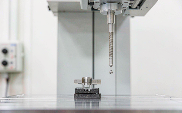
- CMM & Optical Measurement
- Material Verification
- Batch Traceability
Medical CNC Quality Control at a Glance
A medical component is controlled across the full production chain — from drawing review to shipment records. The table below shows what is verified at each stage.
| Quality Stage | What We Verify |
|---|---|
| Drawing Review | Dimensions, tolerances, GD&T, special requirements and datum strategy |
| Material Verification | Grade, specification and supplied material documentation |
| First Article | First-part dimensional conformity before wider production |
| In-Process Inspection | Critical dimensions at defined production stages |
| Final Inspection | Drawing dimensions and specified quality requirements |
| Surface Inspection | Roughness, finish, burrs and visible defects |
| Documentation | Inspection records and agreed certificates |
| Traceability | Batch / material / production records where required |
What Makes Medical CNC Parts Different?
Medical components are judged less on “high precision” as a slogan and more on whether specific failure modes are controlled. Five risks matter most.
Dimensional Accuracy
A dimensional error can affect assembly, fit, functional movement, sealing or alignment. Critical dimensions are identified before production and checked against the drawing.
Material Conformity
“Titanium” or “stainless” is not a complete specification. Alloy, grade, applicable standard and lot must be confirmed against the order and material documentation.
Surface Integrity
Burrs, scratches, roughness, machining marks and residual contamination can affect function or cleanliness. Surface requirements are defined per feature, not assumed.
Batch Consistency
The first part being conforming does not guarantee the 500th. In-process monitoring and final verification keep later parts within the same limits.
Traceability
A record chain from raw material through machining and inspection to shipment lets a quality issue be investigated and contained. Traceability scope is agreed per project.
Why a Framework, Not a Claim
We describe the control points and the evidence we can produce. Blanket precision slogans are avoided because they do not tell a buyer how a specific part is actually controlled.
Our Medical CNC Quality Control Process
Each step answers: what is required, why it matters, how it is controlled, how it is inspected, and what evidence supports it.
1 · Drawing & Specification Review
Requirement: 2D drawing, 3D CAD, dimensional tolerances, GD&T, surface finish, material and inspection requirements are fully defined.
Risk: Unclear or conflicting requirements lead to out-of-spec parts even with good machines.
Control: Critical-to-quality characteristics are identified before production and reflected in the control plan.
Inspection: Drawing and CAD are reviewed against the request for quotation and order.
Evidence: Reviewed drawing and agreed specification form the baseline for all later inspection.
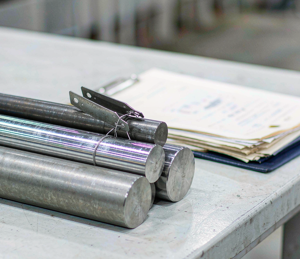
2 · Material Verification
Requirement: The stock matches the ordered grade, standard and condition.
Risk: Wrong stock or incomplete documentation causes material mismatch that survives machining.
Control: Supplied material is verified against the order specification and available material documentation before machining.
Inspection: Grade, certificate and heat / lot identification are checked at incoming stage.
Evidence: Material certificate and incoming verification record where the quality agreement requires it.
3 · DFM & Process Review
Requirement: The part can be manufactured and inspected reliably.
Risk: Poor tool access, thin walls, deep cavities, small holes or undefined datums make conformance unstable.
Control: Tool access, corner radii, datum strategy, fixturing and machining sequence are reviewed and planned.
Inspection: Process plan and fixturing are validated on the first setup.
Evidence: Agreed process route and first-setup confirmation.
4 · In-Process Inspection
Requirement: Critical dimensions stay within limits during production.
Risk: Tool wear and thermal variation cause dimensional drift across a batch.
Control: Critical dimensions are checked at predefined production stages according to the control plan and drawing.
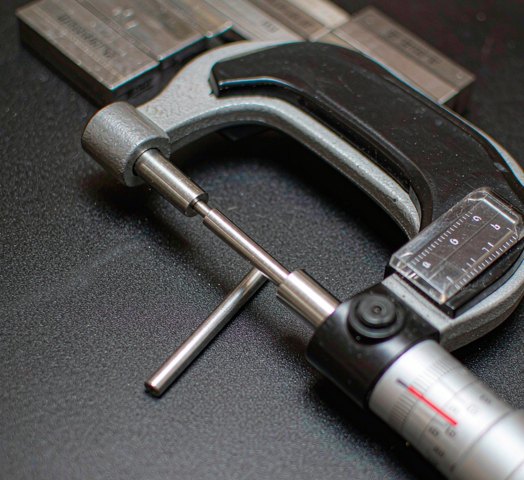
Inspection: Caliper, micrometer, height gauge, bore gauge, optical measurement or CMM as applicable.
Evidence: In-process measurement records at the agreed frequency.
5 · First Article Inspection (FAI)
Requirement: The first produced part conforms to the drawing before wider production.
Risk: A process error repeated across a full batch is costly and unsafe for medical use.
Control: For a new part number or newly established process, the first article is inspected against the drawing and quality requirements.
Inspection: Full dimensional verification of critical features, surface requirements, material and special characteristics.
Evidence: FAI report available for applicable projects. We use “First Article Inspection / FAI” unless the program specifies a formal AS9102 FAIR system.
6 · Final Inspection
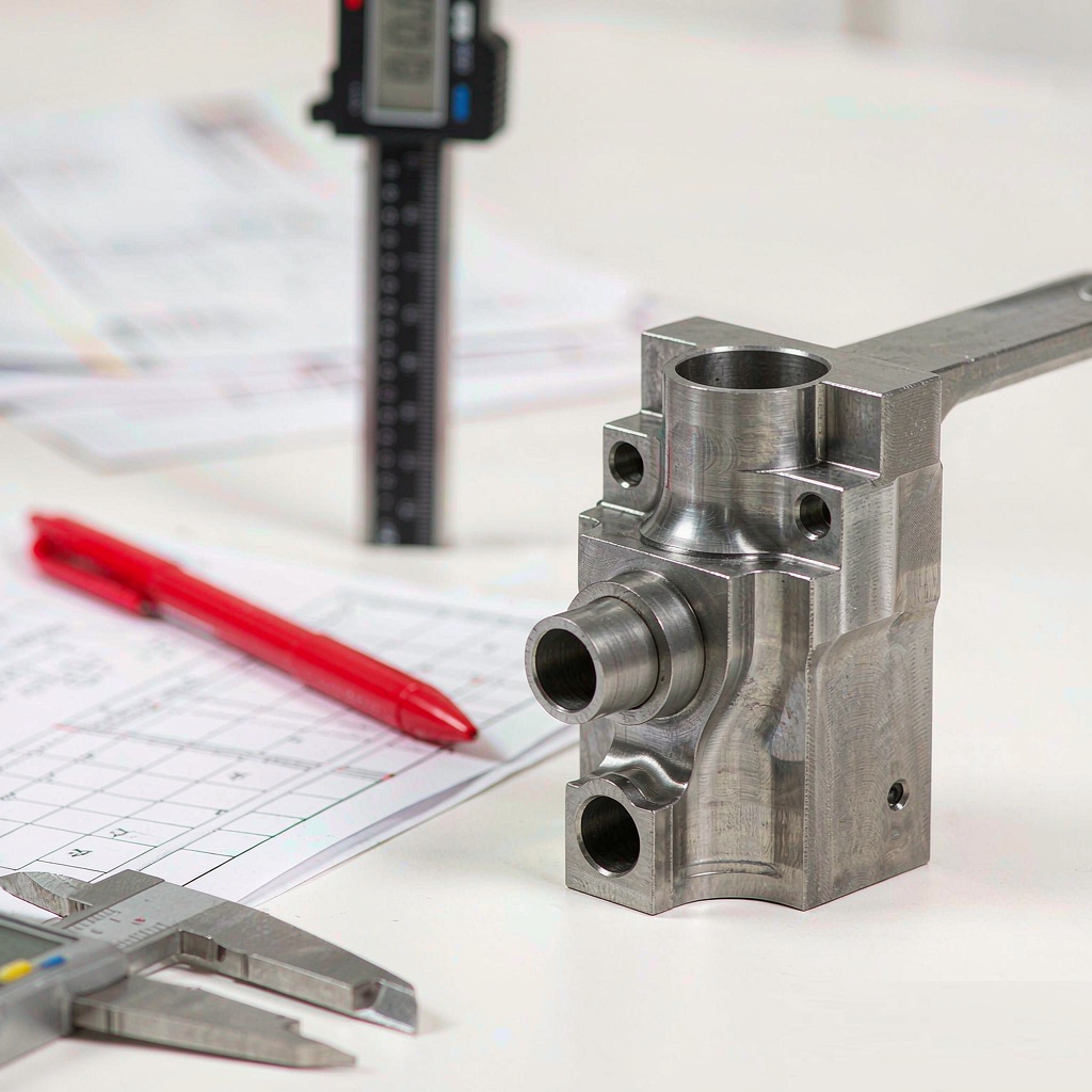
Requirement: Finished parts meet the drawing and specified quality requirements.
Risk: Conformance checked only in-process may miss post-processing change.
Control: Final dimensional verification is performed on the shipped parts or an agreed sample.
Inspection: CMM, micrometers, calipers, height gauges, thread gauges and surface checks as specified.
Evidence: Dimensional inspection report where requested.
7 · Surface and Cleanliness Inspection
Requirement: Edges, roughness and visible condition meet the drawing or agreed requirement.
Risk: Burrs, scratches or contamination affect function, assembly or cleanliness.
Control: Deburring and finishing follow the agreed edge and surface requirements; handling is controlled.
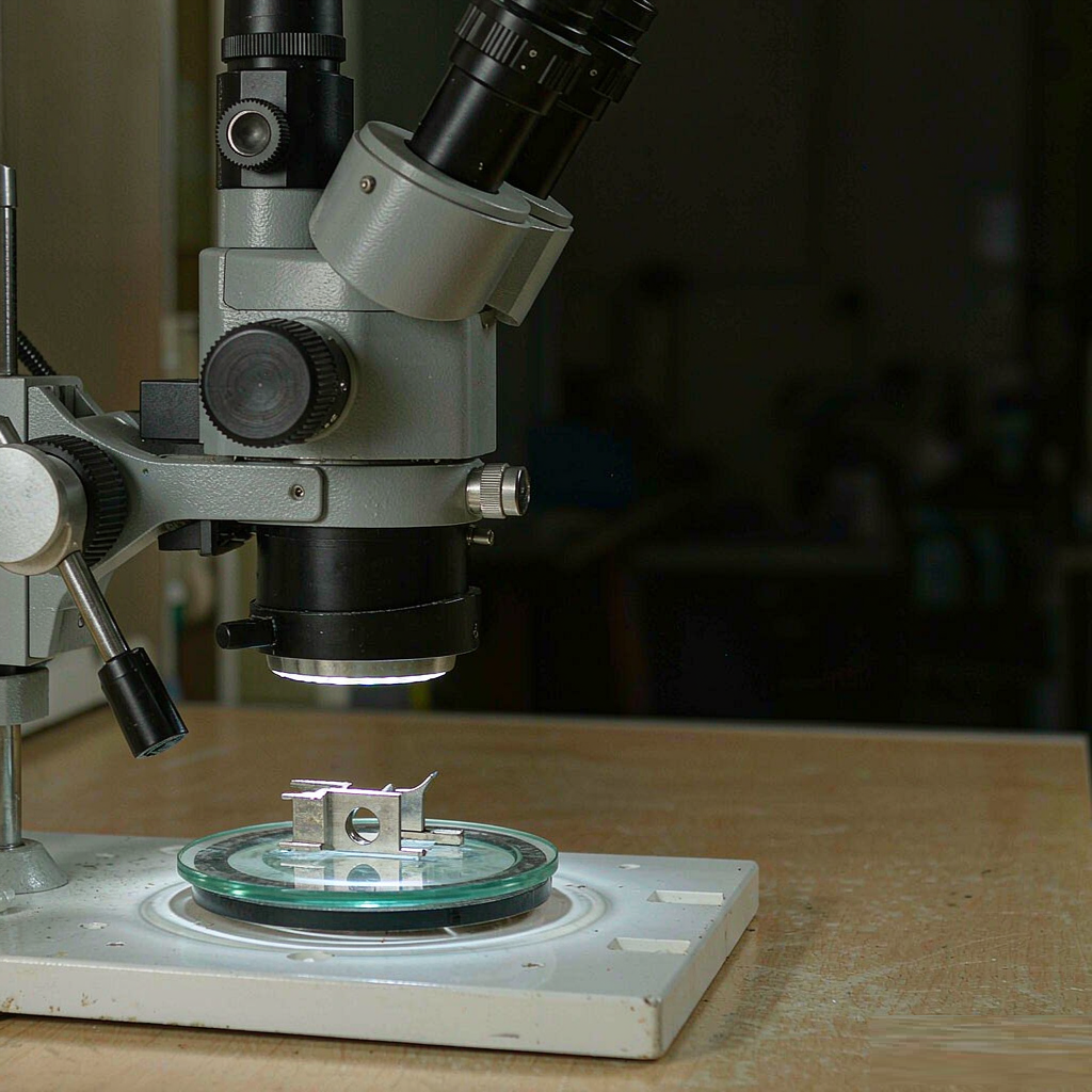
Inspection: Visual inspection, magnification where critical, and roughness measurement where specified.
Evidence: Surface finish report where specified; visual inspection record.
8 · Documentation & Traceability
Requirement: The part can be demonstrated conforming and, where required, traced.
Risk: Without records, a field issue cannot be investigated or contained.
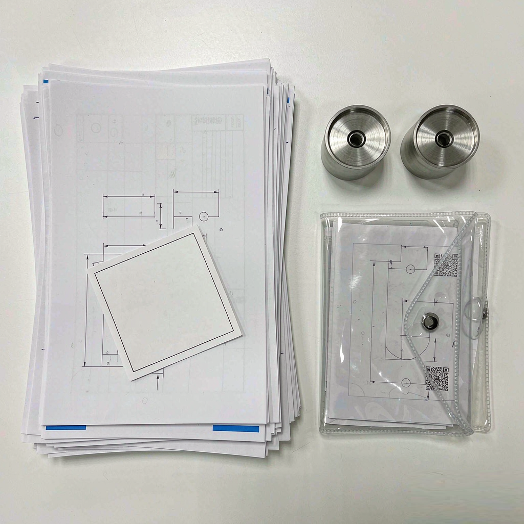
Control: Inspection records and agreed certificates are compiled per the quality agreement.
Inspection: Documentation completeness is checked before release.
Evidence: Inspection report, material certificate, CoC, FAI and traceability records according to project scope.
Medical CNC Tolerances & GD&T
Tolerance is not a single number applied to a whole part. It is set by the drawing and confirmed by the features that matter for fit and function.
Critical Dimensions
Bore, shaft, locating surface, mating interface and sealing surfaces receive targeted control. Non-critical features are held to standard commercial limits to keep cost reasonable.
Geometric Tolerances
Position, flatness, perpendicularity, parallelism, concentricity / runout and profile are read and executed from the GD&T callouts on the drawing.
Capability, Not a Promise
Typical achievable capability for qualified features is in the range of ±0.005 mm to ±0.01 mm, set by drawing, material, geometry and inspection plan. Tight-tolerance features are confirmed after engineering review.
Inspection Methods by Requirement
| Requirement | Typical Verification Method |
|---|---|
| Linear dimension | Micrometer / CMM |
| Hole diameter | Bore gauge / CMM |
| Position | CMM |
| Flatness | CMM / surface measurement |
| Surface roughness | Profilometer where available |
| Thread | Thread gauge |
| Visual defects | Visual inspection / microscope |
Methods marked “where available” depend on the equipment configured for the project. Inspection conditions follow the applicable measurement procedure and customer specification rather than a fixed ambient number.
Inspection Equipment for Medical CNC Parts
Equipment is listed by what it verifies, so the link between requirement and measurement is clear.
CMM
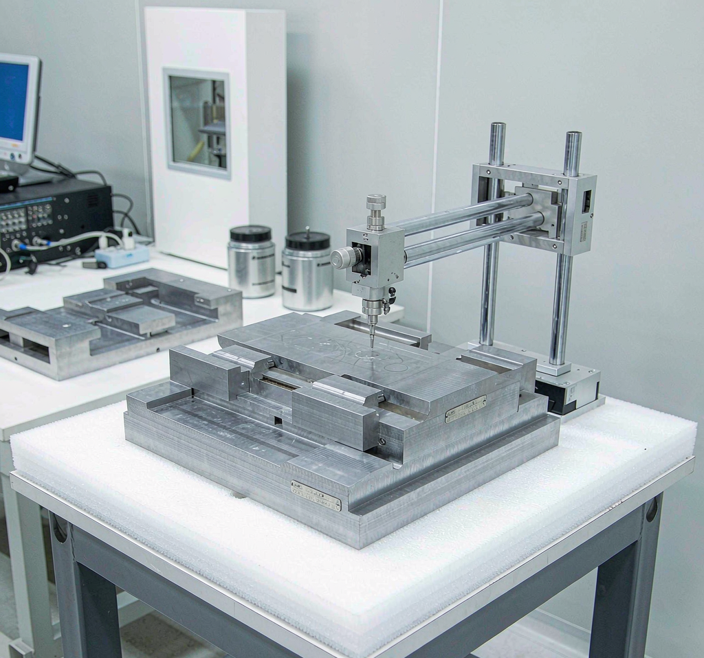
Used for dimensional verification, position, profile and GD&T on complex or critical features. The primary evidence tool for final inspection.
Optical Measurement
Used for small features, contours, edges and visual dimensional checks where contact measurement is impractical.
Micrometers & Gauges
Calibrated micrometers, calipers, height gauges and bore gauges for dimensional checks and process verification.
Thread Inspection
Thread gauges for internal and external threads, checked per the drawing class and requirement.
Surface Roughness Measurement
A profilometer is used where a specified Ra value must be verified. Applied only where the drawing or order requires it.
Equipment vs Capability
Listing equipment does not mean every project receives every check. The inspection scope follows the drawing and the agreed quality plan.
Medical Material Verification
Material is confirmed by grade, standard and documentation — not by name alone. Common medical CNC materials we work with:
Titanium
Grades such as Grade 2 and Ti-6Al-4V are verified against the ordered grade and material certificate. Titanium medical machining is covered in our dedicated titanium medical CNC page.
Stainless Steel
316L and other medical grades are confirmed by certificate and lot. Corrosion resistance and cleanability depend on grade and finish. See our stainless steel CNC machining page.
Aluminum
Selected aluminum grades are used where weight and machinability matter. Grade and temper are verified per order. See our aluminum alloy selection guide.
PEEK & Medical Plastics
PEEK and other engineering plastics are verified by grade and lot where used. See our PEEK CNC machining page.
Surface Finishing & Post-Processing Quality
Finishing affects function and cleanliness. We distinguish what is performed in-house from what is coordinated with a qualified external process.
Deburring
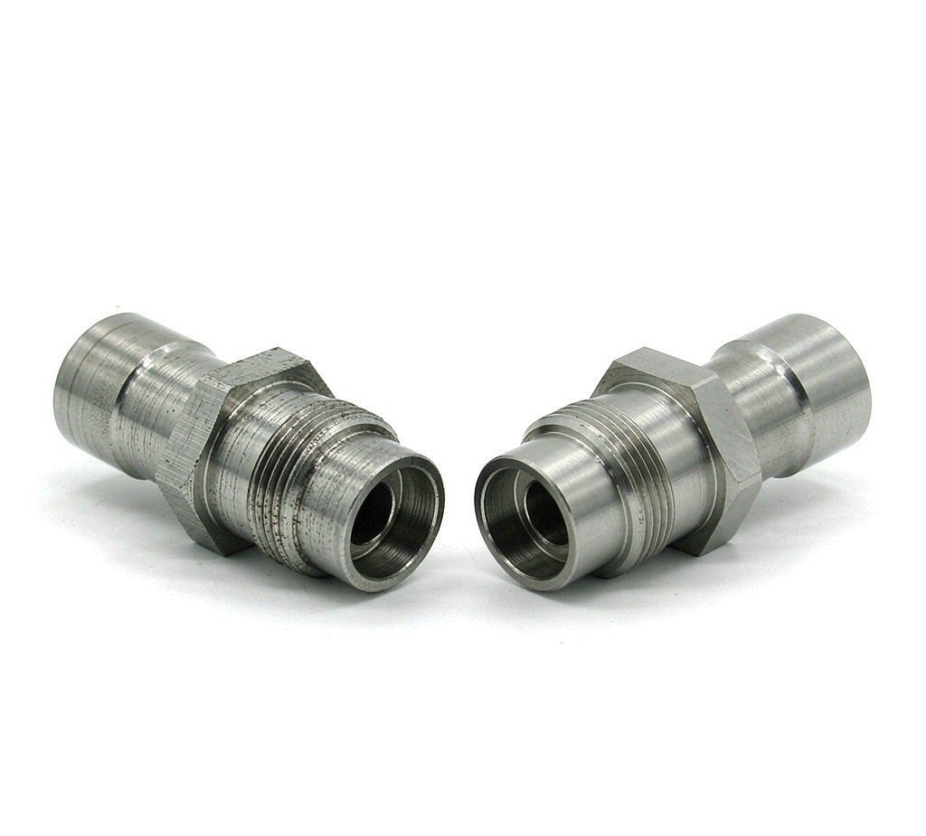
Burrs are removed according to the drawing or agreed edge requirement, then verified visually or by magnification where critical.
Passivation & Electropolishing
For stainless parts, passivation or electropolishing may be specified. These are coordinated with qualified external processes where not performed in-house.
Anodizing & Polishing
Anodizing (aluminum) and mechanical polishing are applied where the drawing or application requires, with finish verified against the specification.
Common Quality Risks in Medical CNC Parts
Naming the failure modes — and the control for each — is more useful than a general quality statement.
| Risk | Possible Cause | Control |
|---|---|---|
| Dimensional drift | Tool wear / thermal variation | In-process measurement |
| Burrs | Tool condition / cutting strategy | Deburring + inspection |
| Warped thin sections | Fixturing / sequence | Process planning |
| Surface scratches | Handling / finishing | Visual inspection |
| Material mismatch | Wrong stock / documentation | Incoming verification |
| Thread failure | Tool wear / process | Thread inspection |
| Batch variation | Process instability | Defined inspection frequency |
| Contamination | Handling / finishing | Cleaning and controlled handling |
Medical CNC Parts Quality Case Study
A representative project type, described without fabricated customer names or numbers.
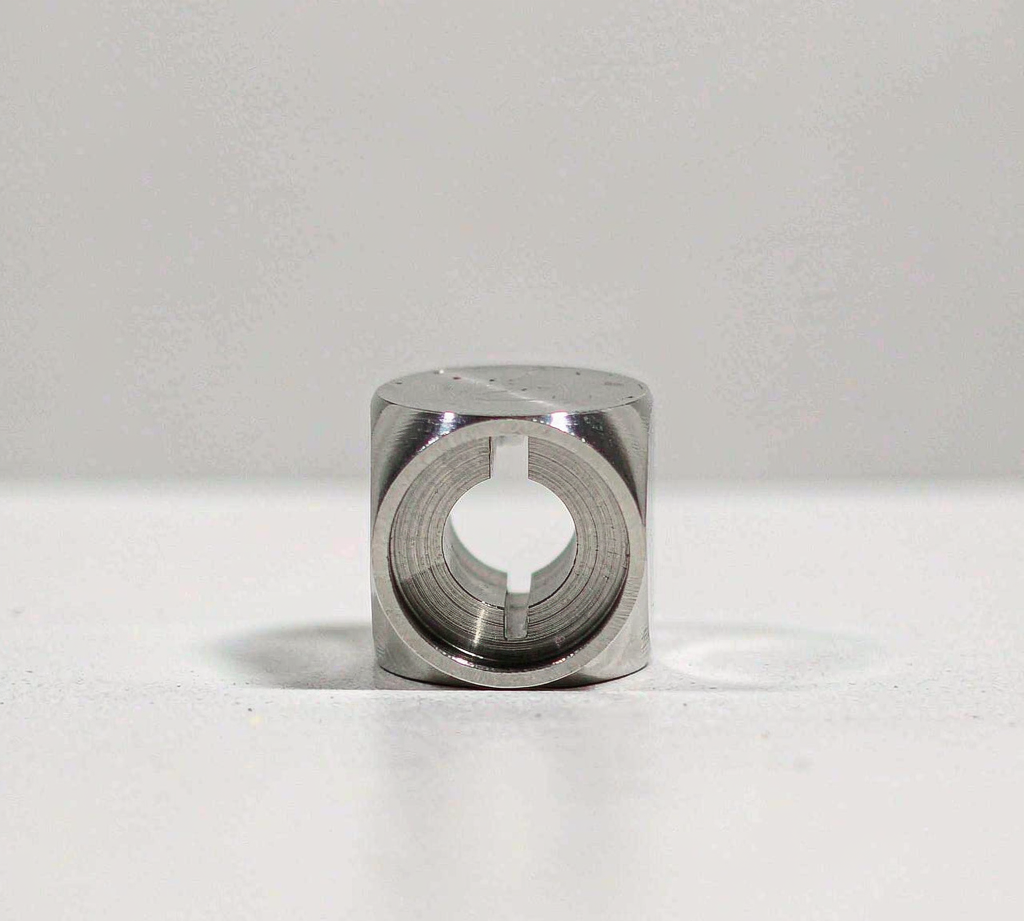
Customer Requirement
A machined component with tight concentricity on a bearing seat and a specified surface finish on a sealing face.
Part Type & Material
Turned and milled cylindrical component in a verified medical-grade alloy, supplied with material certificate.
Critical Dimensions & Surface
Bearing-seat diameter and runout held to the drawing; sealing-face roughness verified to the specified Ra.
Inspection Plan
First article inspected, then in-process checks on the bearing seat and final CMM verification of concentricity and position.
FAI & Final Inspection
FAI report issued for the new part number; final inspection on the released batch per the control plan.
Quality Documentation
Dimensional inspection report, material certificate and CoC provided according to the project quality agreement.
Medical CNC Inspection Reports & Quality Documentation
Documentation availability follows what Goldcattle can actually provide. Items not in our standard scope are not listed to look complete.
| Document | Availability |
|---|---|
| Dimensional Inspection Report | Available on request |
| Material Certificate | According to material / order |
| Certificate of Conformance | According to project requirement |
| FAI Report | Available for applicable projects |
| Surface Finish Report | Where specified |
| Traceability Records | According to project requirement |
| RoHS Documentation | Where applicable |
| Other Quality Records | Project specific |
PPAP, AS9102 FAIR, IQ/OQ/PQ and biocompatibility reports are not assumed. They are included only when the program scope and customer agreement explicitly require them.
Material & Production Traceability
A traceable part carries a record chain from stock to shipment. The depth of that chain is defined by the customer’s quality system, part risk and documentation needs.
Full lot-level traceability is confirmed on a project-by-project basis, not assumed for every order.
Medical CNC Manufacturing vs Medical Device Regulatory Compliance
A CNC component supplier and a finished device manufacturer carry different responsibilities. Confusing the two weakens credibility.
What a Component Supplier Does
Manufactures components to customer drawings, specifications and agreed quality requirements, with material verification, inspection and records as defined by the supply agreement.
Where Regulation Sits
Regulatory obligations for the finished device — including the U.S. FDA Quality Management System Regulation (QMSR), effective February 2, 2026, which incorporates ISO 13485:2016 — apply to the finished device manufacturer, not automatically to every component supplier.
Process Controls That Affect Medical CNC Quality
These are the engineering reasons behind the inspection results above — supporting context, not the page theme.
Tool Selection & Wear
Tool grade and condition are chosen for the material and feature; wear is monitored so critical dimensions stay stable.
Cutting Parameters
Speed, feed and depth are set for surface quality and dimensional stability rather than maximum removal alone.
Coolant & Workholding
Coolant control and stable fixturing reduce heat variation and movement that would otherwise shift dimensions.
Machining Sequence
Roughing, semi-finish and finish passes are ordered to manage residual stress and distortion on thin or long features.
Handling & Cleanliness
Controlled handling between operations protects edges and surfaces from scratches and contamination.
Why Listed Last
These controls explain how quality is achieved; the inspection, tolerance and documentation sections explain what is verified and proven.
Medical CNC Parts Quality Checklist
A practical checklist for buyers to use when reviewing a supplier’s quality capability.
Before Production
- Drawing reviewed
- GD&T identified
- Material grade confirmed
- Critical features identified
- Surface requirements defined
During Production
- Tool condition monitored
- Critical dimensions checked
- Fixturing verified
- Process records maintained
Before Shipment
- Final dimensions verified
- Burrs / surface defects checked
- Material documentation available
- Required inspection report completed
- Packaging requirements confirmed
Frequently Asked Questions
Related Medical CNC Resources
Request a Medical CNC Quality Review
Send your drawing, material grade, critical features, surface requirements, inspection scope and traceability needs. Our engineering team can review the manufacturing and quality requirements and propose a control plan.
- ✓ Drawing-based inspection
- ✓ FAI & CMM verification
- ✓ Material verification
- ✓ Agreed quality documentation
- ✓ Traceability per project
- ✓ ISO 9001:2015 system