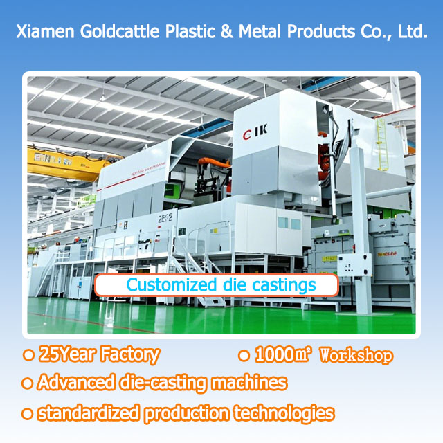
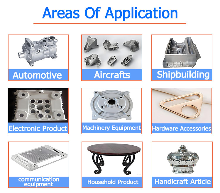
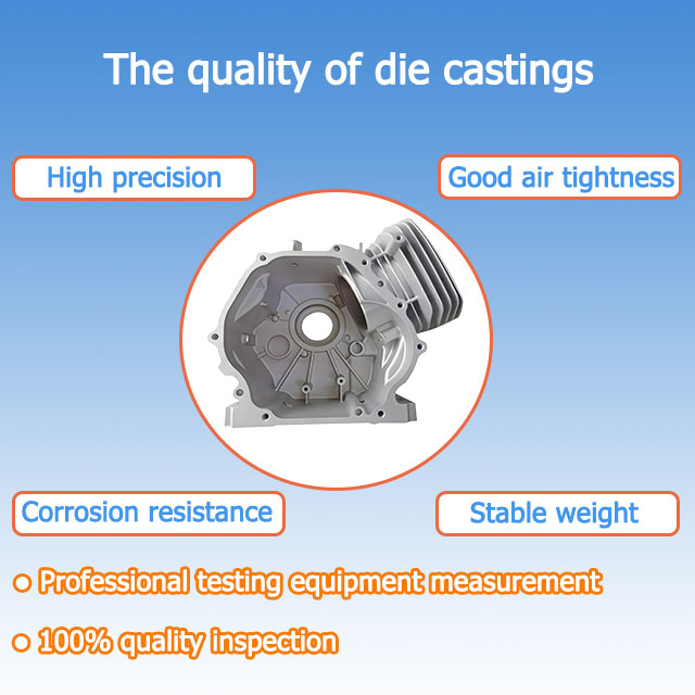
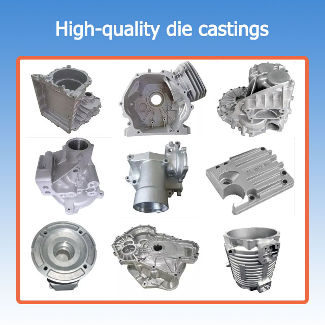
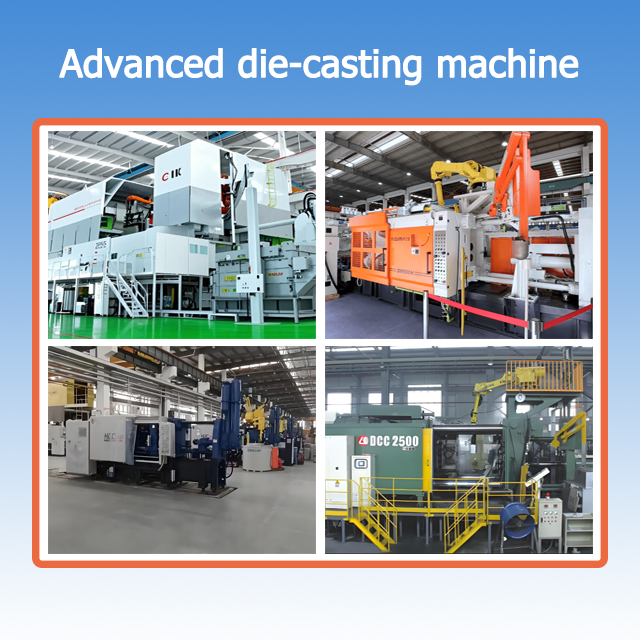
Aluminium Gravity & Die Casting Housings | A356/ADC12
Description
Custom Aluminum Cast Housings & Enclosures, Made to Your Drawing
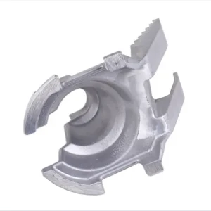
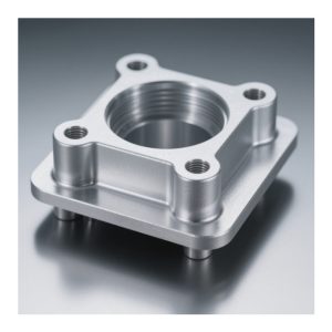
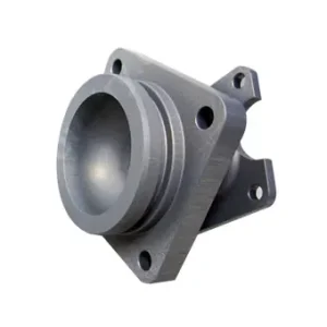
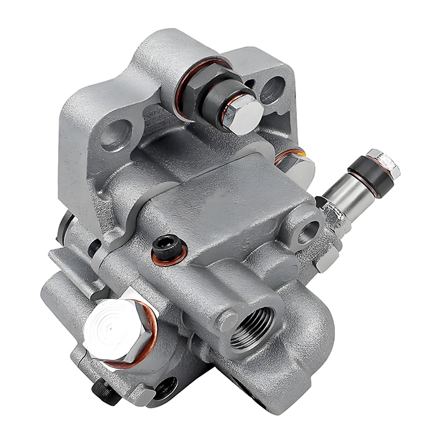
We make cast aluminum housings for pumps, motors, gearboxes, electronics and thermal equipment. The cast shape comes first. The sealing faces, bores and threads are machined after.
We review the casting route, the alloy, the machining allowance and the check plan before a tool is cut. You get one supplier for the casting and the finished interfaces.
Built from a 3D model and a 2D drawing. No standard catalogue. No stock sizes.
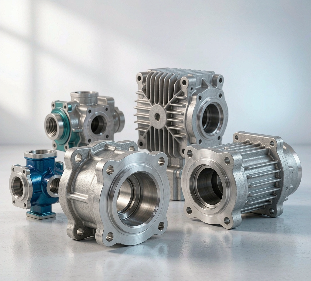
01 / One part
One drawing, one owner
We make the housing you designed. We do not offer a stock range of enclosures.
02 / Interfaces
Cast shape, machined faces
Sealing faces, bores, threads and mounting pads are finished after casting.
03 / Route
Process chosen for the part
Gravity, low pressure or high pressure casting is picked from your geometry and volume.
04 / Evidence
Checks agreed up front
The inspection plan is written from your drawing before tooling starts.
1 · What This Page Covers
Short answer: We make custom cast aluminum housings and enclosures from your drawing, then machine the faces that have to seal, locate or carry a load. We do not sell standard boxes, and we do not assign a pressure or ingress rating from the casting process alone.
A housing is not just a casting. It is a set of working interfaces. A pump housing has a port face and a gasket land. A gearbox housing has a bearing bore and a shaft opening. An electronics enclosure has a lid seat and a flat thermal pad. When one of these faces is wrong, the assembly leaks, binds or overheats even if the outside shape looks right.
That is why this page starts with the part you are buying, not with a list of machines. We describe the housing families we make, the design decisions that change the tool, the machining work that finishes the interfaces, and the records you can ask for.
From your CAD
A 3D model and a 2D drawing define the shape, the critical sizes and the finish. An approved sample can be used when a drawing is not complete.
Casting plus finishing
Casting, heat treatment where required, CNC machining, surface finish and the agreed checks are managed as one order.
What we do not claim
We do not state a blanket tolerance, a fixed lead time, a pressure class, an ingress rating or a certified system level for a cast housing on its own.
Read this before you compare quotes
Two quotes for the same housing can cover very different work. One may stop at the raw casting. Another may include machining, finishing and a first article report. Ask each supplier to list what is included. A lower casting price can hide a missing sealing face or a missing check.
2 · Six Housing Families We Make
Short answer: Pump and valve housings, motor and gearbox housings, industrial equipment housings, electronics enclosures, heat sink housings, and new-energy equipment housings. Each one puts a different demand on the casting and on the machining.
Pump and valve housings
Flanged ports, internal flow passages, threaded connections and a flat gasket land. The cavity and the sealing face decide the tool layout.
Motor and gearbox housings
Bearing bores, shaft openings, mounting feet and cooling ribs. Bore position and alignment matter more than the outer shape.
Industrial equipment housings
Mounting pads, thick bosses, lifting points and access covers. Local thick areas need attention to avoid shrinkage.
Electronics and electrical enclosures
Lid seats, gasket grooves, connector openings and flat thermal pads. Sealing faces must stay clean through coating.
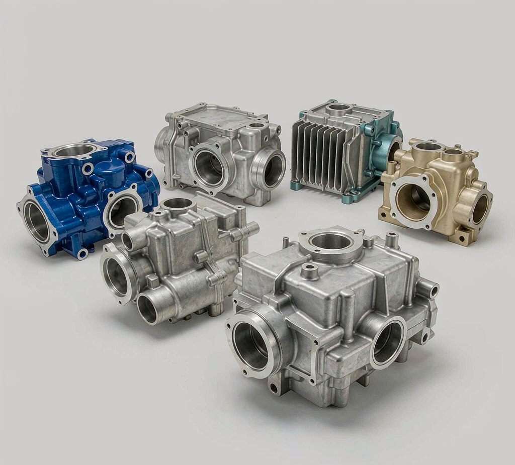
Heat sink and thermal housings
Parallel fins, a flat contact pad and a short heat path from the inside wall to the fins. Fin draft and fin spacing both affect the tool.
EV and new-energy equipment housings
Long shallow ribs, large flat covers and many fixing points. Flatness across a wide face is often the hardest part of the job.
What each family asks us to define first
Swipe the table to see all columns.
| Housing family | Faces that are machined | Main casting risk | Define in your RFQ |
|---|---|---|---|
| Pump and valve | Port face, gasket land, thread holes, bore | Internal cavity shape and core support | Medium, test plan, allowed leak |
| Motor and gearbox | Bearing bore, shaft opening, motor pad | Shrinkage around thick bosses | Bore sizes, alignment datum, heat treatment |
| Industrial equipment | Mounting pads, cover seat, tapped holes | Hot spots at thick to thin transitions | Load points, flatness, finish |
| Electronics enclosure | Lid seat, gasket groove, connector face | Warpage of a wide flat cover | Gasket type, masking, ingress test plan |
| Heat sink housing | Contact pad, fixing holes | Incomplete fin fill and fin draft | Fin direction, contact flatness, airflow side |
| New-energy equipment | Large cover face, fixing pattern | Flatness over a long span | Cover size, seal layout, inspection points |
These are product families, not stock parts. If your design sits between two rows, we treat it as its own drawing and review it on its own terms.
3 · Why a Housing Is More Than a Casting
Short answer: A casting gives you the shape. Machining gives you the working interfaces. Most housing failures show up at the joint between the two.
A buyer often receives a good looking casting that will not seal. The outside is fine. The gasket land is wavy, a bore is out of position, or a threaded hole breaks into a pore. These are not cosmetic issues. They stop the assembly.
Sealing faces
Flatness, surface texture and an unbroken gasket land. Coating must be masked off these faces.
Bores and datums
Bearing seats, dowel holes and pilot diameters set how the assembly lines up.
Threads and pads
Tapped holes and mounting pads carry clamp load. A pore under a thread is a leak path.
Thermal paths
A flat contact pad and a sound wall between the heat source and the fins.
A practical rule. Mark the faces that seal, locate or carry load on your drawing. We build the datum plan and the machining allowance around those faces. A casting drawing without marked critical faces gives the tool maker no priority to work to.
Cast state and machined state are not the same thing
Swipe the table to see all columns.
| Feature | How it leaves the casting | What machining changes | What the drawing should say |
|---|---|---|---|
| Sealing face | As-cast surface with draft and parting line | Flat land, controlled texture, groove where needed | Flatness, finish, groove width, masking |
| Bearing bore | Cored hole or solid boss | Bored size, roundness, position to datum | Size, position, datum reference |
| Fixing holes | Cored or as-cast boss | Drilled and tapped to a stated thread | Thread, depth, engagement, edge distance |
| Outer wall | As-cast, with draft | Usually left as-cast, then finished | Appearance standard, coating, visible faces |
| Thermal pad | As-cast or lightly machined | Flat contact surface for the mating part | Flatness and finish on the contact area |
We do not publish one tolerance for a whole housing. Cast sizes and machined sizes are reviewed on each feature from your drawing. A measuring machine accuracy is not the same as a casting tolerance, and we do not mix the two.
4 · Choosing the Casting Route for Your Housing
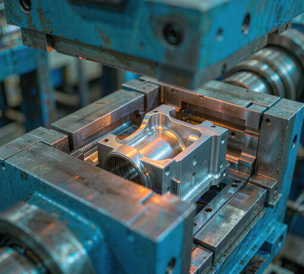
Short answer: Gravity die casting, low pressure die casting and high pressure die casting are three different routes. We pick one from your wall thickness, internal cavity, alloy, volume and drawing. We do not pour one process name over every housing.
Swipe the table to see all columns.
| Route | How the metal fills the cavity | Where it fits a housing | What to check on your design |
|---|---|---|---|
| Gravity die casting | Metal flows into a reusable steel mold under its own weight | Thicker walls, larger housings, cavities that suit a sand or permanent core, heat treatable cast alloys | Feeding, riser marks, wall transitions, machining stock |
| Low pressure die casting | Controlled air pressure pushes metal up into the mold | Housings that need a steadier fill and a sounder wall than a simple gravity pour | Fill path, gating position, porosity on sealing faces |
| High pressure die casting | Metal is injected fast into a steel die under high pressure | Thin walls, fine ribs, high repeat volumes, complex outside shape with simpler inside shape | Core pulls, trapped gas, draft on fins, machining allowance |
Each route has its own tool, its own alloy family and its own filling behaviour. A page that lists all three under one heading and then quotes one tolerance for all of them is not describing a real order. We agree the route in writing before the tool is cut.
Wall and cavity
A closed internal passage may need a core. A core needs support and a way out. This changes the parting line and the tool cost.
First order and repeat demand
A stable repeat order can justify a production die. A small or changing design often starts on a simpler route.
Soundness needs
If a face must hold a seal or a test pressure, we discuss the fill path and the check plan at the start, not after the first sample.
For a full explanation of each process, see our die casting services page. For alloy and design theory, see the aluminum die casting guide. For a process decision, see die casting versus CNC machining. This page stays with the housing you are buying.
5 · Alloy Families, Kept Separate
Short answer: Cast alloys and wrought alloys are not interchangeable. A356 and AlSi7Mg belong to gravity or permanent mold work. ADC12 and A380 belong to high pressure die casting. 6061 is a wrought alloy used when we machine a housing from solid stock instead of casting it.
The old version of this page put all of these grades into one material table. That is wrong. A casting alloy is chosen for how it flows, feeds and solidifies. A wrought alloy is chosen for how it cuts and how it behaves after rolling or extrusion. We confirm the grade we can actually buy for your project before we quote.
Swipe the table to see all columns.
| Alloy family | Used with | Why a buyer asks for it | What we confirm before quoting |
|---|---|---|---|
| A356 / AlSi7Mg / AlSi10Mg | Gravity die casting or permanent mold casting | Cast alloys that can suit heat treatment and sounder, thicker sections | Grade standard, supply, heat treatment state, test piece needs |
| ADC12 / A380 / A383 / A384 | High pressure die casting | Good filling behaviour for thin walls, ribs and complex outside shapes | Grade standard, supply, porosity plan on sealing faces |
| A360 / A413 | High pressure die casting | Chosen for particular corrosion, sealing or filling needs | Grade standard, supply, finishing compatibility |
| 6061 and other wrought grades | CNC machining from plate or billet, not casting | A housing that is better cut from solid than cast, often for small runs or a flat wide face | Plate thickness, distortion after cutting, finish |
We do not print property tables from a catalogue
Strength, hardness and elongation depend on the grade, the heat treatment, the section thickness and the test method. We give you values only when the material supplier document and the agreed test support them. Numbers copied from a general table are not evidence for your part.
We also do not claim a certificate we cannot show. If your order needs a material document, a composition check or a specific test report, say so at the enquiry stage. We then state what can be supplied for that material lot. Our materials overview explains how we describe standard grades and available grades across the site.
6 · Shape Decisions Before the Tool Is Cut
Short answer: Wall transitions, ribs, bosses, draft, parting line and machining stock decide most housing problems. These are drawing decisions, and they are far cheaper to change before steel is cut.
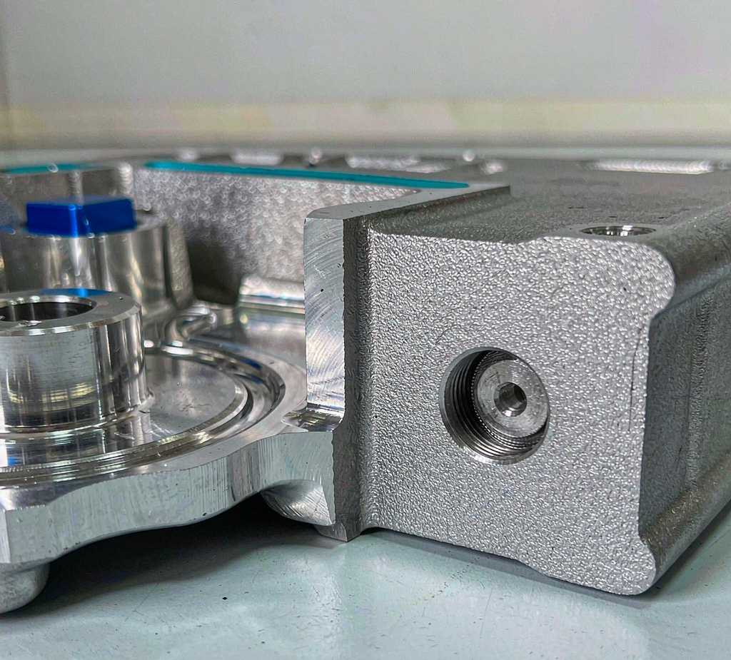
We review your model as a casting first. A shape that is easy to machine from billet can be hard to feed as a casting. A shape that casts well may leave no clean place to hold a seal. Both views are needed at the same time.
Our review looks at the fill path, where the metal will shrink, how the part leaves the tool, and where the cutters will later touch. We send back comments on the drawing. We do not quietly change a dimension to make the tool easier.
Send the model early. A small change to a boss or a fillet at this stage can remove a shrinkage risk. The same change after the tool is built means new steel.
Swipe the table to see all columns.
| Design area | What goes wrong | What we agree on the drawing | Who is affected |
|---|---|---|---|
| Wall thickness | Sudden thick to thin steps cause shrinkage and hot tears | Even walls, gradual transitions, blend radii | Tool design and casting yield |
| Ribs | A rib thicker than the wall creates a hot spot at the root | Rib to wall ratio, root fillet, rib direction | Filling and surface sink marks |
| Bosses | Heavy bosses stay hot and pull a shrink cavity under a thread | Boss size, coring, local feed, hole depth | Machining and leak paths |
| Draft | No draft traps the part in the tool or drags the surface | Draft direction and angle from the parting line | Tool life and as-cast finish |
| Parting line | A line across a sealing face leaves a step to machine away | Where the halves meet, where flash is trimmed | Sealing face and appearance |
| Cores and slides | An undercut inside a cavity may need a pull or a separate core | Core support, core prints, access for cleaning | Tool cost and internal passage quality |
| Ejector marks | Pin marks on a visible or sealing face | Pin positions, which faces stay unmarked | Appearance and sealing |
| Machining stock | Too little stock leaves as-cast skin; too much opens pores | Allowance on each machined face, datum targets | CNC setup and surface soundness |
None of these rows needs a number printed on a public page. The right value depends on the alloy, the route and the shape. We put the agreed values on the reviewed drawing, not in a general chart.
7 · Porosity and the CNC Interface
Short answer: Gas pores can sit just below the cast skin. Machining into that layer can open them on a sealing face. We reduce the risk with the fill design, the machining allowance and an agreed check plan. We do not promise a pore-free casting.
This is the single most misunderstood part of a cast and machined housing. A raw casting can look perfect. When the sealing face is milled, a line of small pores appears and the gasket will not hold. The problem is inside the wall, not at the machine.
Trapped gas and shrinkage
Fast filling can trap air. Thick sections can shrink as they cool. Both leave voids in the wall. The pattern depends on the route and the tool design.
After the cutter passes
Machined sealing lands, bored holes, tapped threads and thermal pads are the usual places. A coating can hide a pore but it will not seal it.
Swipe the table to see all columns.
| What you see | Likely cause | Review point before tooling | Check that can be agreed |
|---|---|---|---|
| Small holes on a milled face | Subsurface gas pores opened by cutting | Fill path, venting, depth of cut, face location | Visual standard, X-ray or CT on defined zones |
| A leak through a tapped hole | Pore linking the thread to the cavity | Boss design, thread depth, core position | Leak test with an agreed medium and pass rule |
| A dip near a thick boss | Shrinkage at a hot spot | Boss size, feeding, local wall transition | Section check on the first article |
| Pores under a plated or coated face | Finish applied over an unsound surface | Face preparation, masking, finish choice | Finish adhesion and surface check |
Some projects use impregnation to seal fine pores. That is a separate process with its own limits. We only discuss it when the part, the medium and the test plan make it suitable. We never present it as a standard feature of every housing.
We also do not quote one blanket dimensional tolerance here. The size we can hold on a machined bore is a different question from the soundness of the wall below it. Both are written into the drawing review.
8 · Sealing Faces, Grooves and Flatness
Short answer: A housing seals because the gasket land is flat, clean and continuous, and because the bolt pattern holds it evenly. The casting does not give you a seal on its own.
Start with the gasket. A flat sheet gasket, an O-ring in a groove and a liquid sealant need different faces. A groove needs a width, a depth and a clean corner radius. A flat land needs a surface texture that suits the gasket. Both need a bolt pattern that clamps evenly around the whole loop.
Swipe the table to see all columns.
| Seal feature | What the drawing should fix | What the tool affects | What machining delivers |
|---|---|---|---|
| Flat gasket land | Flatness, texture, bolt pattern, land width | Parting line, draft, ejector positions | Flat land with an agreed texture |
| O-ring groove | Groove width, depth, corner radius, gland fill | Whether the groove is cast or fully milled | Continuous groove with no step at the parting line |
| Port face | Port size, thread, face squareness to datum | Core position and support | Face, thread and bore in one setup where possible |
| Cover seat | Flatness over the full span, fixing points | Warpage of a wide thin cover | Skim cut or a straightening step if agreed |
| Masked areas | Which faces stay free of coating | Not applicable | Masking before finishing and a clean handover |
Ingress and pressure ratings are test results, not casting features
A cast enclosure does not carry an IP rating just because it has a gasket. It also does not carry a pressure class just because the wall looks thick. A rating needs a defined test method, a test medium, a pressure or exposure, a hold time and an agreed pass rule. We state a rating only when that plan and its result are part of the order.
If your housing must hold pressure or keep water out, put the requirement in the RFQ. We will then tell you which test we can run, what record it produces, and what has to be decided before the tool is made.
9 · Fins, Heat Paths and Thermal Housings
Short answer: A thermal housing needs a short path from the heat source to the fins, a flat contact pad, and fins that the casting route can actually fill. We do not publish heat loss figures from a general table.
Fins are a casting problem as much as a thermal one. A tall thin fin is easy to draw and hard to fill. A fin without draft sticks in the die. A fin that is too close to its neighbour traps air and leaves a short shot. The direction of the fin also has to match the airflow in the finished assembly.
Contact pad
The face the heat source sits on. It is machined flat so the mating part touches across the full area.
Wall behind the fins
A thick wall slows the heat path and adds a shrink risk. A thin wall can warp. We review both from the model.
Fin shape and draft
Height, spacing, root fillet and draft are set with the tool maker before the die is cut.
Tell us which side faces the airflow and where the heat source sits. If the housing also has to seal, the sealing face and the thermal pad both need a machining step. We plan the setup order so that one operation does not spoil the other.
Ask for a thermal test only if you need one. A calculated heat figure is not the same as a measured result. We agree the test method and the record before we quote it.
10 · CNC Machining After Casting
Short answer: We face mill the sealing lands, bore the bearing seats, drill and tap the fixing holes, mill grooves and spot face the pads. The datum plan comes from your drawing and from the as-cast shape.
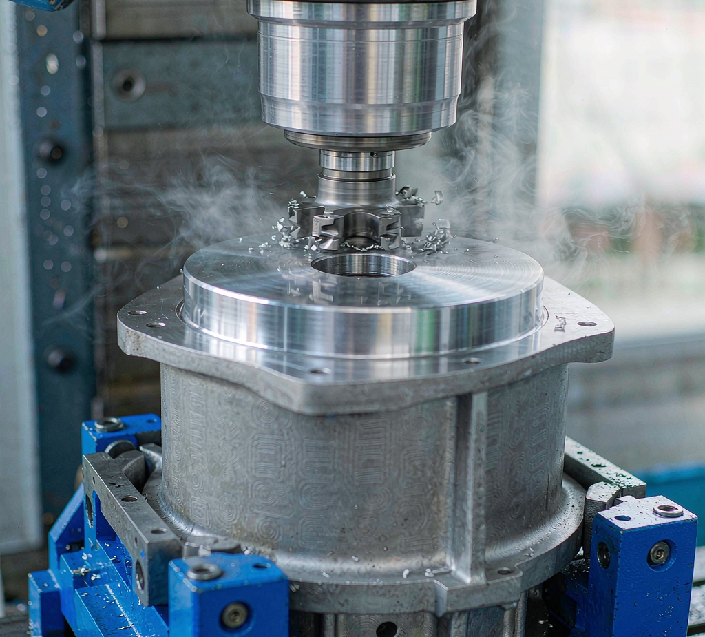
A casting has no flat, square reference until we create one. We pick stable as-cast points for the first setup, cut the primary datums, then hold the part for the remaining work. Where the shape allows, we group faces into one setup so related sizes stay together.
Swipe the table to see all columns.
| Operation | What it produces | Why the housing needs it | Typical check |
|---|---|---|---|
| Face milling | Flat sealing land or cover seat | A gasket needs a flat, continuous surface | Flatness and surface texture |
| Boring and reaming | Bearing seat, pilot bore, shaft opening | Alignment of the assembled shaft or rotor | Size and position to datum |
| Drilling and tapping | Fixing and port threads | Clamp load and connection to other parts | Thread gauge and hole position |
| Groove milling | O-ring groove or gasket channel | A controlled seat for the seal | Groove width, depth and continuity |
| Spot facing | Flat pad under a bolt head | Even clamp load on an as-cast wall | Pad flatness and position |
| Deburring and cleaning | Clean edges and clear passages | Loose chips and flash damage seals and flow paths | Visual check and passage clear check |
We do not say that every housing needs five axis work. Some parts are finished in three setups on a simpler machine. The goal is a stable datum plan and fewer re-clamps, not a longer machine list. Our precision CNC machining and 5 axis CNC machining pages describe the wider capability. This page stays with the housing interfaces.
11 · Surface Finishing for Enclosures
Short answer: Powder coating, painting, electrophoretic coating, conversion coating, anodizing and bead blasting are all possible. We choose from the alloy, the environment and the faces that must stay bare. We do not publish unverified temperature or salt spray numbers.
A finish changes sizes. A coated bore gets smaller. A painted gasket land loses its flatness. Threads fill up. That is why masking and check sizes are agreed before the part is coated, not after a buyer finds the lid will not close.
Swipe the table to see all columns.
| Finish | Why a buyer asks for it | What must be agreed | Faces at risk |
|---|---|---|---|
| Powder coating | Colour, outdoor appearance, a thick protective layer | Colour, masking, final check sizes | Threads, bores, gasket lands |
| Painting | Brand colour or a specific look on visible faces | Colour standard, visible face list, masking | Sealing faces, thermal pads |
| Electrophoretic coating | Even coverage on a complex outside shape | Coverage needs, masking, check sizes | Internal passages, threads |
| Conversion coating | A thin base layer or a simple protective treatment | Compatibility with the alloy and any later finish | Contact pads that need conductivity |
| Anodizing | A hard, coloured surface on a suitable aluminum grade | Alloy suitability, colour, final sizes after the layer | Bores, threads, press fits |
| Bead blasting | An even, clean as-cast look before a finish | Texture standard, which faces are blasted | Machined lands and bores |
Finish claims need test evidence
A coating thickness, a corrosion test result and a temperature limit are only meaningful with a stated test method and a record for that batch. We do not repeat general numbers from a supplier brochure as a promise for your housing. If you need a specific test, ask for it in the RFQ and we will state what we can supply.
12 · Inspection and the Records You Can Ask For
Short answer: We write a check plan from your drawing. It can cover a material document, a first article report, key dimensions, X-ray or CT on defined zones, a leak test and finish checks. We do not claim one blanket report for every housing.
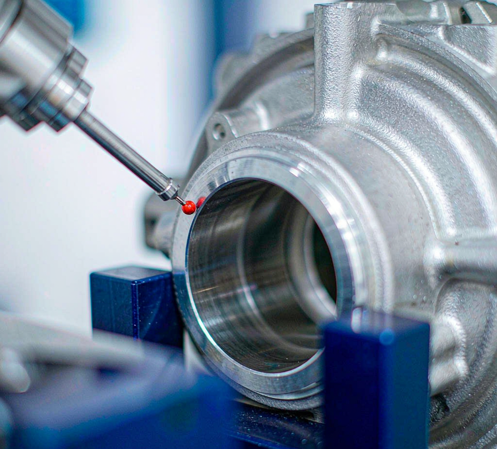
A buyer should know what will be measured, on how many parts, with which method, and what document will be sent. Those four lines prevent most arguments at the first article stage. We put them in the quote.
We also separate three things that are often mixed up: the capability of a measuring machine, the tolerance on a machined feature, and the soundness of a cast wall. A good report lists each one on its own line.
Ask for the records at enquiry. Adding a leak test or a radiographic check after the tool is built can change the tool design and the price.
Swipe the table to see all columns.
| Check | What it covers | When it applies | Record you can request |
|---|---|---|---|
| Material document | Alloy grade and the lot used for the casting | When the order calls for it | Supplier document for that lot |
| First article report | Key sizes on an early part from the agreed route | When the drawing defines the features | Dimensional report against the drawing |
| Dimensional check | Machined bores, lands, flatness, hole position | At the frequency agreed in the plan | Measurement record |
| X-ray or CT | Internal soundness in defined zones | When the seal or load path needs it | Images and an acceptance note |
| Leak or pressure test | Whether the housing holds under the agreed test | Only with a defined medium, pressure, time and pass rule | Test record with the test conditions |
| Finish check | Coating coverage, thickness where agreed, masking | When a finish is part of the order | Finish record and visual standard |
| Visual standard | Flash, trim marks, pores on visible faces | Agreed per part and per face | Acceptance note or sample boundary part |
We do not write that every size is checked on every part, or that every housing is radiographed. Those are decisions in the check plan. We also do not name a specific measuring machine brand or quote an instrument accuracy as if it were a part tolerance.
13 · From Sample to Repeat Production
Short answer: Drawing review, process and alloy plan, tool design, sample casting and machining, first article checks, then repeat orders under revision control. We do not print a fixed lead time or a fixed minimum order for every housing.
Drawing review
Mark the sealing faces, bores, datums and the check plan.
Route and alloy
Agree the casting route, the grade and the machining allowance.
Tool design
Fix the parting line, draft, cores, feeding and ejector points.
Sample parts
Cast, machine and finish a first batch against the drawing.
First article
Run the agreed checks and close any open points.
Repeat orders
Hold the drawing revision, the tool and the check plan together.
A sample route and a production route are not the same thing. A housing cut from billet may pass an early fit check but behave differently when cast. We say which route a sample came from, so a fit approval is not mistaken for a tooling approval.
Revision control matters on repeat orders. When you change a boss or a gasket land, the tool, the machining program and the check plan may all need an update. Send the new revision before the next batch, not after it.
14 · Tooling Ownership and Total Cost
Short answer: The tool, the machining setups, the finish and the check plan are the four cost drivers. We agree tool ownership in writing before we build it. We do not print a break-even number or a tool life figure that we cannot support.
Driver 01
The casting tool
Cores, slides, parting line and cavity size set the tool cost. A simpler cavity is cheaper to build and easier to keep running.
Driver 02
Machining setups
Every extra re-clamp adds time and a chance to shift a datum. Grouping related faces lowers both.
Driver 03
Finish and masking
Masked sealing lands, threads and thermal pads add hand work. Agree the mask list early.
Driver 04
Inspection plan
Radiography, leak tests and first article reports are real work. Ask for them in the quote, not later.
Tool ownership is a contract term, not a favour. Ask for it in the quote. We do not assume one rule for every project, and we do not use a tool built for one order on another order without agreement.
Compare total part cost, not just casting price
A cheap raw casting can cost more once you add a sealing face, a thread repair, a leak test and a rejected batch. Ask for the scope of each quote in one line: casting only, or casting plus machining plus finishing plus the agreed checks.
We do not publish mould life, yield, defect rates, minimum order sizes or fixed delivery days on this page. Those depend on the route, the alloy, the tool and the order. We state them in the quote for your part when we can support them.
15 · When Casting Is Not the Right Route
Short answer: Casting is not always the best answer. A small run, a very flat wide face or a simple open shape can be better made by CNC machining from billet or by sheet metal fabrication. We say so at drawing review.
Swipe the table to see all columns.
| Route | When it fits better | What you give up | What you gain |
|---|---|---|---|
| Cast plus CNC | Repeat volumes, a curved cavity, integrated bosses and ribs | A tooling step and a casting check plan | Near net shape, fewer machined hours per part |
| CNC from billet or plate | Small runs, changing designs, a wide flat sealing face, 6061 type alloys | More material removed, longer cycle time per part | No casting tool, fast design changes, sound wrought material |
| Sheet metal fabrication | A thin wall cover or an open box shape with simple sealing needs | Integrated bosses, thick pads and complex internal passages | Light weight, simple tooling, easy finishing |
See our die casting versus CNC machining page for a full cost and volume comparison, and our sheet metal fabrication page for formed enclosures. If you are not sure which route fits, send the model and we will answer against your part.
16 · Questions Buyers Ask First
Usually a pore is opened on the sealing face. The wall can hold gas just below the cast skin. Milling into that layer exposes it. We review the face location, the fill path and the check plan before the tool is made.
Related: porosity and sealing faces.
Not as a normal casting alloy. 6061 is a wrought grade. It belongs on the CNC from billet route. We keep cast alloy families and wrought alloy families in separate tables.
Related: alloy families and other routes.
Often no. A simple shape can be cut from billet or made on a short-run route. We tell you which route fits and we label the sample so it is not taken as a tool approval.
Related: sample to production.
Cooling and handling. A wide thin wall can warp as it cools, and a heavy skim cut can add stress. We review the wall, the ribs and the setup order from the model.
Related: design rules and CNC work.
Only with a defined test. We agree the method, the exposure, the hold time and the pass rule first. The casting process by itself does not give a rating.
17 · What to Send for a Quote
Short answer: A 3D model, a 2D drawing with critical faces marked, the alloy and finish, the quantities, and the test or record you need. The more of this you send, the fewer questions we have to ask later.
3D model STEP or IGES, with the latest revision noted.
2D drawing Sizes, datums, GD&T where used, and marked critical faces.
Application What the housing holds and how it is assembled.
Alloy and state Grade, heat treatment if needed, or a request for our advice.
Casting route Your preference, or ask us to propose one.
Part size Overall size, wall thickness range and approximate weight.
Sealing needs Gasket type, groove, medium and any leak test.
Finish Coating, colour, and which faces must stay bare.
Quantities First order size and expected annual demand.
Records Material document, first article, X-ray or CT, finish check.
Tool terms Ownership, storage and revision rules.
Delivery needs Packing, label, and the delivery window you are working to.
Send the housing drawing. We will answer against your part.
We will come back with the casting route we propose, the alloy family, the faces we would machine, and the check plan we can support. If a billet or sheet metal route fits better, we will say so.
What to expect in the reply
- A process route, not a list of machines.
- The open drawing questions that need your answer.
- The checks and records we can include in the quote.
- Tool ownership written as a clear term.
18 · Frequently Asked Questions
Do you keep standard aluminum housings in stock?
No. We make housings from your drawing or an approved sample. We do not sell a standard housing catalogue. The shape, the alloy and the checks are set by your part.
What should I send to get a quote?
Send a 3D model and a 2D drawing. Add the alloy, the part weight, the wall thickness range, the sealing faces, the critical bores, the finish, the first order size and the expected annual volume. Tell us if the design may still change.
Which casting process do you use for housings?
We choose between gravity die casting, low pressure die casting and high pressure die casting. The choice depends on the wall, the internal cavity, the alloy, the volume and your drawing. We agree the route before a tool is cut.
Is 6061 a casting alloy for these housings?
No. 6061 is a wrought aluminum alloy. It is not a normal gravity casting or high pressure die casting alloy. We use it when a housing is machined from solid plate or billet instead of being cast.
Can you machine sealing faces after casting?
Yes. Most housings need machined sealing faces, bores and threaded holes. We agree the machining allowance and the datum plan at drawing review, before the casting tool is made.
Can CNC machining open up holes inside the casting?
It can. Gas pores can sit just below the cast skin. Cutting into that layer may open them on a sealing face. We review the critical faces, the tool design and the check plan to lower that risk.
Do your cast housings carry an ingress or pressure rating?
Not by default. A rating needs a defined test, a test method and an agreed pass rule. We only state a rating when the test plan and the result are part of the order.
Can you leak test a housing?
Yes, when it is in the agreed check plan. We define the test medium, the test pressure, the hold time and the allowed leak with you first. We do not assume one test for every housing.
Which aluminum alloys can you supply?
Cast alloy families include A356, AlSi7Mg and AlSi10Mg for gravity or permanent mold work, and ADC12, A380, A383, A360 and A413 for high pressure die casting. We confirm the grade we can buy for your project before we quote.
Can I get a sample before a production tool is built?
Often yes. Simple shapes can be made by CNC machining from billet or by a short-run casting route. We tell you which route fits the shape at drawing review. A sample route does not replace a production tool.
Who owns the casting tool?
Tool ownership is agreed in writing before we build the tool. Ask for the term in the quote. We do not use a tool from one order for another order without agreement.
What inspection records can I ask for?
Ask at the enquiry stage. The plan can cover material documents, a first article report, key dimensions, X-ray or CT checks, leak test results and finish checks. We state what we can supply for your part. We do not claim one blanket report for every housing.
Still have a question about an alloy, a groove or a test? Send the drawing with the question. We answer against your housing, not against a general guide.
Related Capability Pages
This page is about cast aluminum housings and their machined interfaces. For wider process topics, see the pages below.
Xiamen Goldcattle Plastic & Metal Products Co., Ltd. Founded in 1998, we make custom parts from drawings or samples. Our work covers CNC machining, injection molding, mold making, 3D printing, die casting and sheet metal fabrication.