

Custom Plastic Electrical Controller Box Enclosure: Waterproof and Dustproof, Industrial Grade Durability
Place of origin : Xiamen, China
Brand Name : JSD
Model : IM-18
Product Material : Plastic
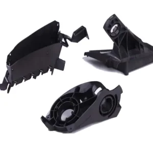
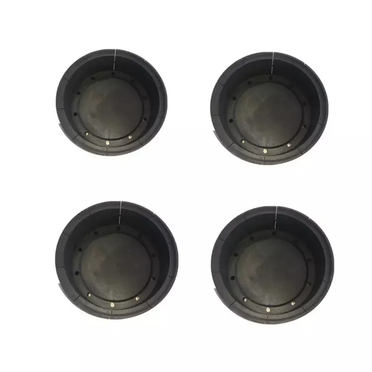
Product Name : Customized Plastic 3D Design Injection Mold Plastic Use Injection Mold Parts
Material : PP, ABS, PA66, PS……
Sample : Available
Features : Customized, high precision
Service : OEM
Certification : ISO9001
Description
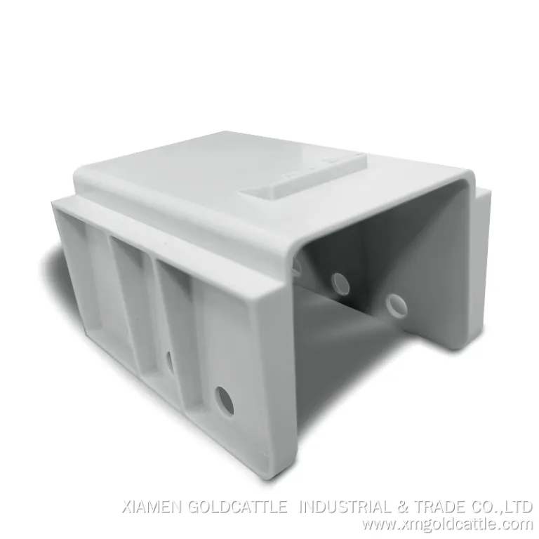
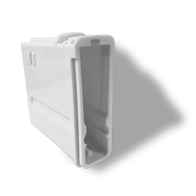
Custom Plastic Electrical Control Box Enclosure
A molded base and separate cover for industrial control, sensor and junction applications, tooled from your drawing. The gasket groove, screw bosses, PCB mounting bosses, ribs, cable entries and wall-mount ears are all formed in the mold rather than added afterwards — which is the only reason a plastic box can hold a seal across a production run.
- Injection molded
- ABS · PC · PC/ABS · PA66 · PP
- Base + cover
- Drawing-based tooling
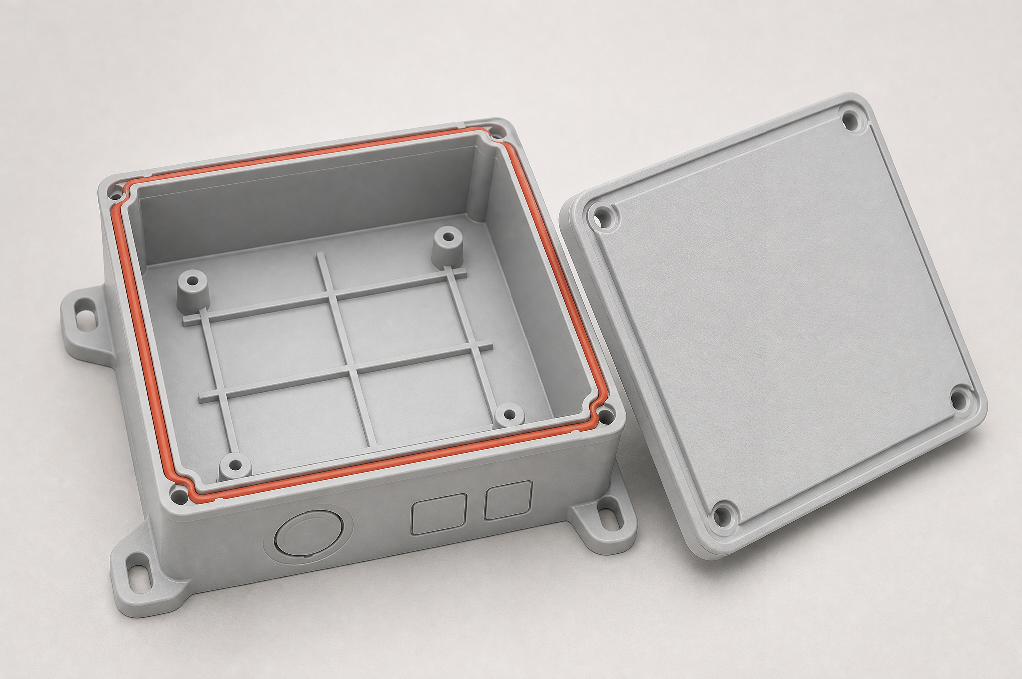
What This Enclosure Is, and What It Is Not
It is a two-part injection-molded box: a base with the internal mounting structure and the sealing flange, and a cover that closes it. What makes it a control box rather than a general-purpose container is that nearly every feature exists to locate or protect something inside it — bosses at the PCB hole pattern, a groove that takes a gasket, knockouts where the cable has to enter, ears where it hangs on a wall.
It is not a certificated enclosure. A molded part can be designed and manufactured to make a seal possible; the IP or NEMA rating belongs to the assembled unit with its gasket, glands and screws, and is established by testing that assembly. That distinction runs through this whole page, because it is the difference between a supplier who understands the standard and one who prints a logo on a data sheet.
1Industrial automation OEMs
Housing for a controller, I/O module or drive that mounts on a machine. The questions are boss positions against the PCB, cable entry direction, and whether the cover clears the tallest component.
Usually asks for: PCB drawing, internal clearance, DIN rail standard.
2Electrical equipment manufacturers
Junction, terminal and small distribution boxes. The recurring requirement is that the enclosure closes consistently and stays closed, which is a screw-spacing and flange-flatness problem more than a material one.
Usually asks for: sealing face flatness, screw torque, gasket material.
3Control system integrators
Small runs of enclosures for a specific project, often with a customer-specified color and legend. Volume is low but the drawing is fixed and the delivery date is not negotiable.
Usually asks for: low-volume tooling, marking, color match.
4Sensor and monitoring suppliers
Compact housings where the wall thickness, the boss height and the cable gland position are all set by a small board and a single connector, and there is very little room for error.
Usually asks for: tight boss tolerance, insert type, small-part handling.
Specification
Every row below is tagged, because only some of this is decided by us. Mold-defined means the feature is produced by the tool and follows a design rule we hold to. Drawing-defined means you set it and we cut to it. Project-confirmed means it is agreed per order and recorded in the quality plan.
- MoldProduct reference
- IM-18, custom enclosure series. The reference identifies the tool and the drawing revision it was cut to.
- MoldProcess
- Thermoplastic injection molding, single or multi-cavity, base and cover in one tool or two.
- MoldConfiguration
- Base with sealing flange + separate cover, tongue-and-groove seam, fastened by screws.
- DrawingMaterial
- ABS, PC, PC/ABS, PA66, PP or PS. Quoted against a named grade and its data sheet, not a family name.
- DrawingOverall dimensions
- A × B × C as specified on your drawing. The tool is cut to that envelope; no stock size is substituted.
- DrawingInternal usable depth
- Set by the overall height minus wall, rib and boss height, and by the cover's internal clearance.
- MoldWall thickness
- Held within ±10% of nominal, typically 2.0–3.0 mm on the walls of a control box. Uniformity matters more than the number.
- MoldRibs
- 0.5–0.7 × wall thickness, height ≤ 3 × thickness, with a fillet at the root to avoid a sink mark on the outside face.
- MoldScrew bosses
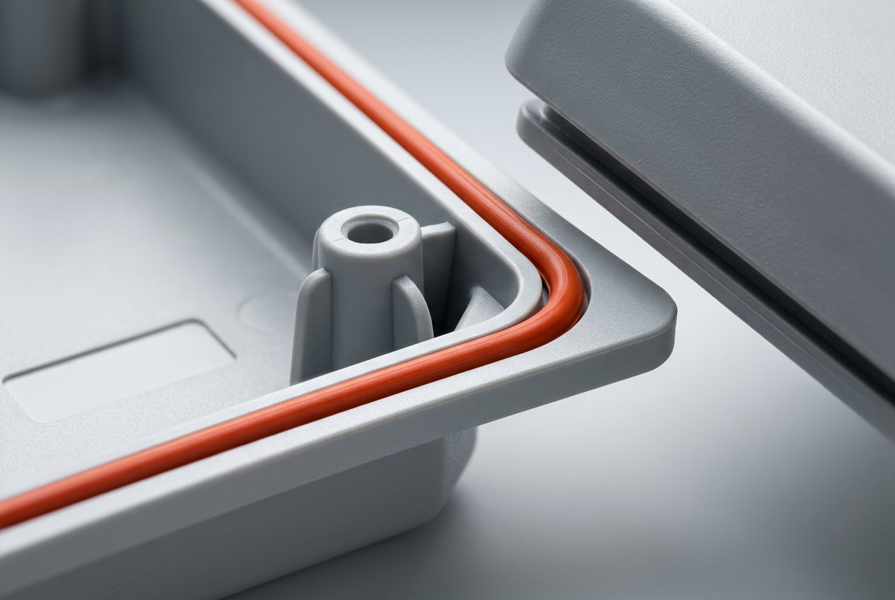
- Boss wall 0.75–0.9 × main wall, gusseted to the side wall and floor. Pilot hole for a self-tapping screw, or a bore for a metal insert.
- MoldGasket groove
- Continuous rectangular groove molded into the base flange, following the corner radii without a break. Section matched to the gasket cord the design specifies.
- DrawingCable entry
- Knockouts or open bores, quantity, diameter and position per drawing. Land left thick enough that the knockout tears cleanly.
- DrawingMounting
- Four corner wall-mount ears with slotted holes outside the seal line, or panel-mount flanges, or DIN rail pads inside.
- DrawingSurface
- Mold texture to a stated grade, or painted. Texture is cut into the tool, so it is a tooling decision as much as a finishing one.
- DrawingColor
- Masterbatch through the resin, or paint. RAL reference and gloss level on the drawing.
- ProjectProtection target
- Stated by you, achieved by the complete assembly, verified by test. The molding is designed to make that achievable.
- ProjectTooling
- New mold, or modification of an existing tool. Quoted as a separate line from the part price.
- ProjectInspection
- First article, dimensional report on the critical features, assembly fit check. Scope recorded in the quality plan per order.
Rows marked Mold-defined are the design rules this tool is built to, not measurements of a particular unit. Rows marked Drawing-defined cannot be stated until your drawing exists — and that is deliberate: a supplier who publishes a fixed dimension table for a made-to-order enclosure is describing a catalog item, not your part.
Structure: Seven Features That Decide Whether It Works
An enclosure looks like a box and behaves like a fixture. Each of the features below does one job, and each one has a way of going wrong that only shows up when the assembled unit is tested or when the first production run is being packed.
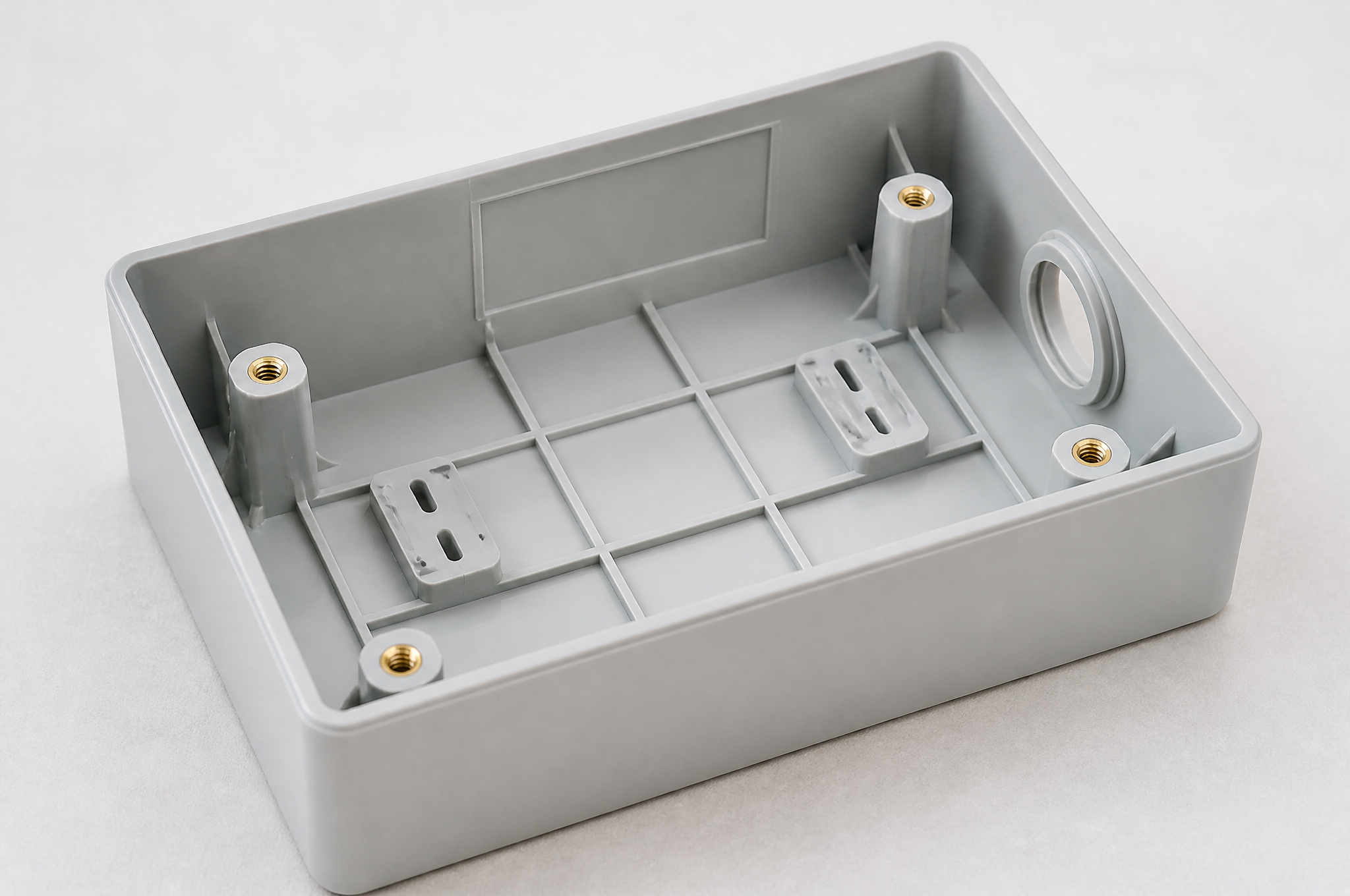
1Base flange and gasket groove
A continuous groove in the flange takes the gasket. The groove has to run unbroken around every corner radius, and its section has to match the cord the design uses — a groove sized for a 3 mm cord will not seal a 4 mm one, whatever the drawing says.
Fails when: the groove is interrupted at a boss, or the corner radius is too small for the gasket to turn without kinking.
2Cover tongue
The cover carries a matching raised tongue that enters the groove and compresses the gasket. The tongue also locates the cover laterally, which is what keeps the two halves aligned when the screws are tightened in the wrong order.
Fails when: the tongue is too shallow to enter before the screws pull, so the gasket is pinched instead of compressed.
3Corner screw bosses
Four bosses sit inside the seal line, gusseted to the wall and floor. Their spacing sets how evenly the gasket is compressed along a long side; on an enclosure over roughly 200 mm, four screws alone usually leave the middle of each side under-compressed.
Fails when: boss wall is too thin and the boss cracks at torque, or the spacing is stretched to save a screw.
4Reinforcing ribs
Ribs on the floor and walls restore stiffness without adding wall thickness. They are also the most common source of a visible sink mark on the outer face, which is why rib thickness is held at 0.5–0.7 × wall and the root is filleted.
Fails when: a rib is run at full wall thickness, and the outside face shows a shadow line on every part.
5Cable entries
Knockouts are molded as a thinned ring so the disc tears away cleanly, or left as an open bore for a gland. The land thickness and the disc diameter decide whether the knockout comes out as a clean hole or takes a piece of the wall with it.
Fails when: the knockout is placed where a gland body will foul an internal component, or the land is too thick to break.
6Wall-mount ears
Ears with slotted holes, molded outside the seal line so the fixing screw never has a path into the enclosure. Slots rather than round holes because wall fixings are never exactly on centers.
Fails when: a fixing hole is placed inside the gasket line, which creates a leak path that no gasket can close.
7Insert or pilot holes
Either a molded pilot for a self-tapping screw, or a metal insert for repeated assembly. The choice is driven by how many times the cover will come off in service and by the pull-out load the design needs.
Fails when: a self-tapping screw is specified into a boss that will be opened monthly, and the thread strips by the third service visit.
8Marking recess
A shallow molded recess on the inside or the lid gives laser marking or a label somewhere flat, protected and repeatable, instead of a curved surface where the print distorts.
Fails when: the recess is put on a face that is also a sealing or mounting surface.
What to Define on the Drawing
A made-to-order enclosure has no fixed dimension table, so the useful thing a product page can publish is the list of dimensions that must be defined — and which of them are constrained by the mold rather than free. The diagram below labels the seven that cause the most rework when they are left to the supplier to guess.
Top view and section. A, B and C set the envelope; P is taken from your PCB; G and t are set by the mold design; CE is where the cable enters.
- AOverall length. You set it. The tool is cut to your envelope.
- BOverall width. You set it, together with A. Both are cut into the cavity.
- COverall height from flange face to the outside of the base. Sets the usable depth.
- PBoss pattern. Comes from your PCB or component drawing, not from us. This is the dimension that most often causes a fit failure.
- tWall thickness. Design rule: uniform within ±10% of nominal.
- GGasket groove width and depth, matched to the gasket cord section you specify.
- CECable entry position, diameter, and whether it is a knockout or an open bore for a gland.
Sealing: What the Mold Decides and What the Assembly Decides
A gasket only seals if it is compressed evenly, and even compression is a geometry problem before it is a material one. The mold can guarantee the groove, the tongue, the flange flatness and the screw positions. It cannot guarantee that the gland was tightened, that the cover was closed in the right order, or that the box was not distorted by being bolted to a wall that is not flat.
| Statement | What it actually means | Who can make it |
|---|---|---|
| Sealing-capable design | The parts carry a continuous groove, a matching tongue, a flat flange and correctly spaced screws, so a gasket can work. | Us, from the drawing. This is a statement about geometry. |
| Tested assembly | A complete unit — enclosure, gasket, glands, screws at the specified torque — passed an ingress test to a stated method. | The party that assembles and submits the unit for test. We support it and can prepare the samples. |
| Certified product | The product is listed by a body to a standard, for a defined range of conditions. | The product owner, after the test report. Not a molder of a bare component. |
Where we stop, in plain terms: we do not describe any molded enclosure as waterproof. We describe it as designed and molded to sealing interfaces, and the rating is whatever the assembled unit achieves in test. If a supplier quotes you IP66 for a bare plastic box, ask which assembly was tested and to which clause.
The four things that actually cause a leak
| Cause | Mechanism | Control |
|---|---|---|
| Flange warpage | The sealing face is not planar, so the gasket is compressed at the corners and loose in the middle of each side. | Balanced wall, symmetric cooling, correct pack pressure, and a flatness check on the machined flange before assembly. |
| Screw spacing too wide | On a long side, the flange lifts between fasteners and the gasket relaxes. | Add screws or thicken the flange locally. This is a drawing decision, made before the tool is cut. |
| Gasket pinched at a corner | The groove radius is tighter than the cord can turn, so the gasket lifts out of the groove exactly where the sealing path turns. | Groove corner radius set from the gasket section, not from the enclosure corner radius. |
| Fixing inside the seal line | A mounting screw passes through the flange inside the gasket, opening a direct path. | Wall-mount ears outside the seal line. Check this on the drawing, not on the sample. |
Material: Chosen by Exposure, Not by Name
The four materials on this product's original data sheet were PP, ABS, PA66 and PS. That is a useful starting set, but a family name is not a specification. What you actually buy is a grade — ABS, ABS+PC, PA66-GF30, UV-stabilized, flame-retardant — and the grade is what the data sheet, the shrinkage figure and the UL listing refer to.
| Material | Choose it when | Watch for |
|---|---|---|
| ABS | Indoor industrial control boxes, good surface and color, predictable cost and tooling. | Standard grades are limited outdoors: UV yellows the surface and embrittles it over time. |
| PC | Impact and a wider temperature range are the requirement, or a transparent cover is wanted. | Higher melt viscosity, more stress in the part, and higher cost. Needs proper drying and a hot runner or generous gate. |
| PC/ABS | A blend of the two: better impact than ABS without the full cost and processing difficulty of PC. | Properties vary widely by blend ratio, so the grade data sheet matters more here than anywhere else. |
| PA66 | Stiffness and heat resistance, often glass-filled, for internal structures and brackets. | Absorbs moisture and moves dimensionally. Dry it before molding and allow for it in the tolerance. |
| PP | Chemical exposure, low weight, and living-hinge features. | Lower stiffness and higher creep. A large flat PP panel will bow unless it is ribbed. |
| PS | Low-cost indoor covers and light internal parts where impact is not a factor. | Brittle in general-purpose grades, and poor resistance to sunlight and many solvents. |
Protection and Compliance: Who Is Responsible for What
Most disagreements on an enclosure project come from a single sentence on a drawing — “IP66”, “NEMA 4X”, “UL94 V-0” — that reads like a material property and is not one. The table below is how we split it.
| Requirement | What we take responsibility for | What we do not |
|---|---|---|
| IP54 / IP65 / IP66 IEC 60529 | Groove geometry, flange flatness, screw positions, cable-entry land, and keeping the seal path unbroken through the mold. | Issuing a rating for a bare molding. The rating comes from testing the assembled unit. |
| NEMA Type 4 / 4X NEMA 250 | Molding to the dimensional and material requirements your design imposes. | Treating IP and NEMA as interchangeable. NEMA covers conditions — corrosion among them — that the IP code does not. |
| UL 94 V-0 / V-2 / HB | Molding a named flame-retardant grade at the wall thickness the listing covers, and supplying the material documentation. | Claiming a rating for “the enclosure” without a grade and thickness. The classification belongs to the resin, the color and the thickness tested. |
| UL 508A | Supplying enclosure parts and material data to the panel builder. | Certifying an industrial control panel. That listing covers the assembled panel, not the empty box. |
| IK07 / IK08 IEC 62262 | Wall thickness, rib layout, boss reinforcement and the material grade chosen to resist impact. | Publishing an IK number without impact testing the assembled unit. |
| CE marking | Material compliance data — RoHS and REACH statements for the grade supplied. | CE-marking a component on the customer's behalf. The declaration belongs to whoever places the finished product on the market. |
One line to remember: a molder can guarantee geometry and material documentation. A rating is a property of a tested assembly, and any supplier who blurs that line is telling you something about how they will behave when the assembly fails.
From Drawing to Production
The tool is the product. Everything that goes wrong in a molded enclosure was decided either in the DFM review or in the first trial, and both of those happen before anything ships.
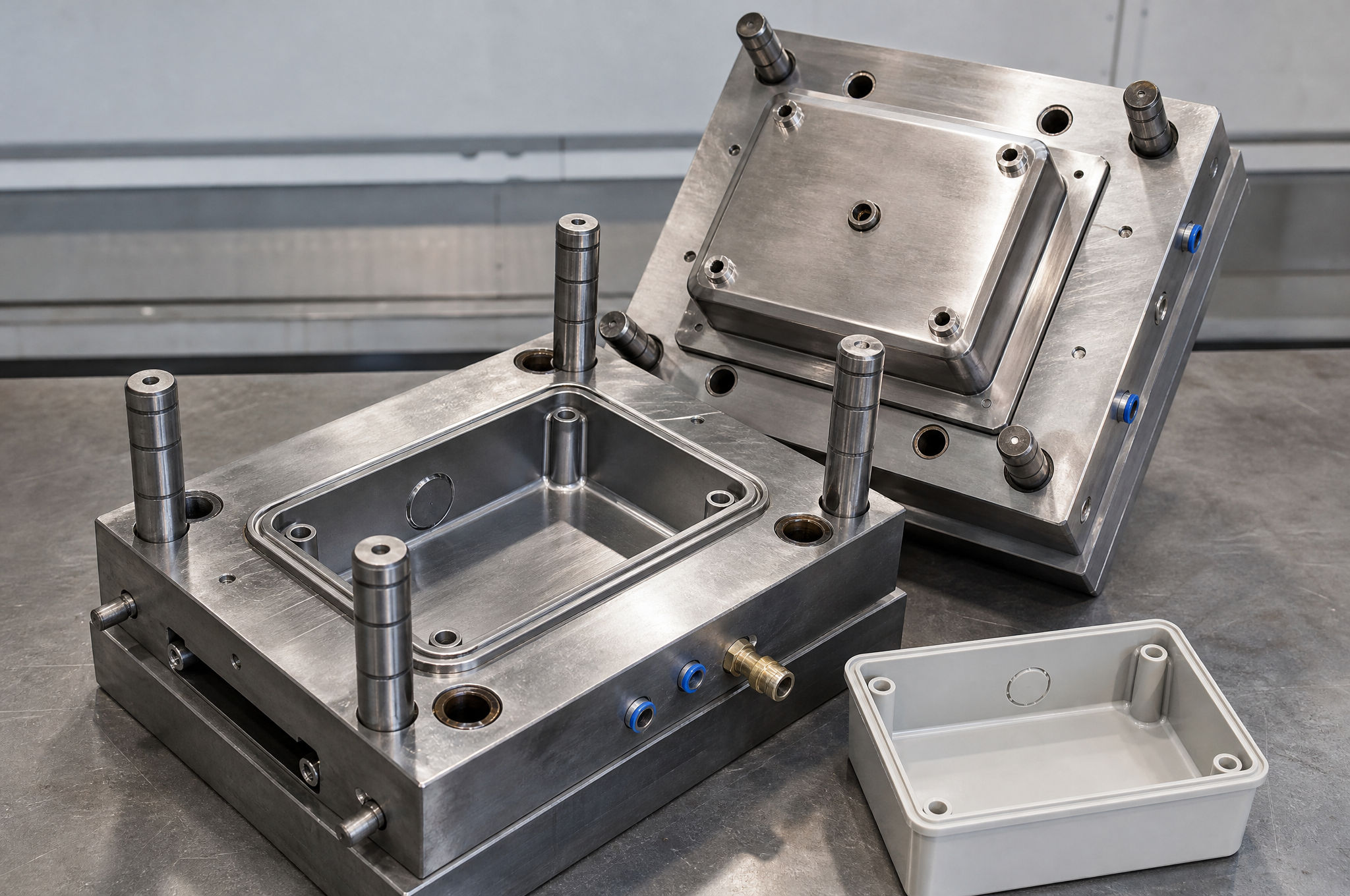
- Drawing and 3D review. Overall envelope, wall uniformity, boss and rib geometry, gasket groove section, internal clearances against the components.
- DFM and mold design. Draft on every vertical face, parting line, gate position, ejection, side actions for any undercut, cooling layout.
- Mold build. Cavity and core cut to the drawing revision, texture applied, water lines and ejector layout finished.
- T0 / T1 trials. First shots checked against the drawing and against the assembly, not just measured in isolation.
- Correction and approval. Steel adjusted where the trial showed it, sample submitted for approval with the dimensional report.
- Production. Molded on the approved parameters with the resin lot recorded, first-off checked each run.
- Finishing and packing. Secondary operations, final inspection, packing to the agreed method.
What drives the tooling cost
| Part size and envelope | Steel block size, machine tonnage and clamp force scale with the projected area of the part. |
| Cavity count | One cavity is cheapest to build; multiple cavities cut part price but multiply tool cost and tooling lead time. |
| Mold steel and life | Tool life is quoted in shots — commonly 100k to 1M+ depending on steel. A short-run tool is a different purchase from a hardened production tool. |
| Side actions | Any feature that cannot release on the parting line needs a slide or lifter, which adds cost and adds a maintenance point. |
| Gasket groove and texture | Fine groove detail and a specified mold texture both add bench work and both have to be cut before the first trial. |
| Trial iterations | Each trial costs machine time and, if steel has to move, toolroom time. A clean DFM review is the cheapest way to reduce them. |
Secondary Operations
Molding produces the box. These operations are what turn it into a part that arrives ready to build with.
Insert molding
Metal inserts placed in the tool and encapsulated during the cycle, for load-bearing threads and repeated assembly.
Ultrasonic welding
A permanent joint between base and cover where the enclosure is not intended to be reopened.
CNC opening
Connector cutouts and gland holes machined after molding where the position or size is not worth putting in the tool.
Laser marking
Model, rating and serial data in the molded recess, permanent and legible at small size.
Painting
Color outside the resin range, or a specific RAL matched to an existing product line.
Assembly and kitting
Gasket fitted, screws bagged, cover attached or packed separately to your build sequence.
Quality: What Gets Checked on This Part
An enclosure passes inspection twice — once as a molding and once as an assembly. The second one is the one that catches the failures a dimensional report cannot see.
| Check | What is measured | What it catches |
|---|---|---|
| Incoming resin | Grade, lot and drying condition against the approved material | A substitution that changes shrinkage, color or flame rating |
| First article | Full dimensional report on the critical features against the drawing | A tool cut to the wrong revision |
| Critical dimensions | Boss pattern, flange height, groove width and depth, overall envelope | The features that decide whether it assembles |
| Sealing face flatness | Planarity of the flange on a reference surface | A warp that would leak at the corners and nowhere else |
| Assembly fit | Cover on base, gasket seated, screws run to torque, sample components fitted | Interference, pinched gasket, boss misalignment |
| Appearance | Sink marks, weld lines, flash, color and texture against the approved sample | Cosmetic rejects found by the customer instead of by us |
Where This Enclosure Is Used
Industrial automation control
Controller and I/O housings mounted on machinery, with cable entry facing the machine and the cover facing the operator.
Sensor and monitoring units
Compact housings where a small board, one connector and a gland define the entire internal layout.
Junction and terminal boxes
Where the requirement is a reliably closed lid, consistent screw compression and a clean knockout for the cable.
Equipment control and pump panels
Wall-mounted boxes for control gear, with the mounting ears kept outside the seal line and the gland entries on the underside.
These are application descriptions, not customer references. We do not publish project names or logos without written permission, and we do not present another product's test results as evidence for this one.
Frequently Asked Questions
Can you mold a plastic control box enclosure from our drawing?
What is the maximum size of an enclosure you can mold?
Can the enclosure be designed for IP65 or IP67?
Which plastic should a control box enclosure be made from?
Can you supply flame-retardant housings to UL 94 V-0?
Can the enclosure include PCB bosses, DIN rail features and threaded inserts?
What drives the cost of a new enclosure mold?
What information do you need to quote an enclosure?
Send the Drawing, the Environment and the Volume
The review that matters happens before the tool is cut. Send the 3D model with the dimensioned 2D drawing, the components that go inside, the cable entry and mounting requirements, and the environment it has to survive. You get a DFM response on wall thickness, draft, boss geometry, groove section and parting line, with tooling and part price quoted as separate lines.
Request a Tooling QuoteDFM review before quotation · STEP, IGES, DWG or PDF drawings accepted