3-Axis, 3+2 Indexed or Simultaneous 5-Axis?
The Decision Framework We Use Before Quoting
Not every complex-looking part requires simultaneous 5-axis machining. Recommending it where 3+2 indexed — or even conventional 3-axis — would satisfy the drawing increases programming cost and cycle time with no dimensional benefit. This page publishes the decision framework our engineering team applies during RFQ review, so you understand exactly how we arrive at the recommended process and why.
The Short Answer
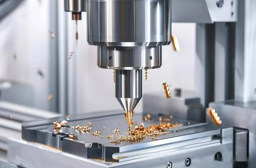
We select the process based on four geometric triggers, not on machine utilisation:
- Does any feature require continuous tool-axis change during cutting? (e.g., impeller blade profiles, turbine airfoil surfaces) → Simultaneous 5-axis is mandatory.
- Are there multiple machined faces at fixed compound angles? (e.g., angled ports on a valve body) → 3+2 indexed is usually sufficient and more cost-effective.
- Can all features be reached from one or two orthogonal directions with prismatic geometry? → Conventional 3-axis may be adequate — we will say so.
- Is the part fundamentally rotational? → CNC turning (or mill-turn) may be the better route, regardless of axis count.
If your geometry falls into category 2 but a supplier quotes simultaneous 5-axis, you are likely paying for capability the part does not require. If it falls into category 1 and someone proposes 3+2, expect visible step marks at index boundaries and potential surface-profile non-conformance.
The Three Options — What Each Actually Means
Understanding the mechanical difference between these modes prevents the most common sourcing error: paying for simultaneous 5-axis when 3+2 would hold the tolerance, or being told 3+2 is adequate when the geometry demands continuous interpolation.
Conventional 3-Axis Machining
The three linear axes (X, Y, Z) move during cutting. No rotary axes participate in the machining operation. The part orientation is fixed throughout.
When it is the correct choice
- Predominantly 2.5D features: pockets, bosses, shoulders, steps, drilled hole patterns
- All machined surfaces accessible from one or two orthogonal directions (top + one side flip)
- Moderate tolerances with no cross-face critical positional relationships
- Cost-sensitive parts where programming overhead directly affects unit economics
- Flat or prismatic geometries without compound-angle features
Limitations to recognise
- Each side flip introduces datum-transfer error (typically 0.005–0.015 mm per re-clamp on well-controlled setups)
- Deep cavities force long tool overhang → deflection, chatter, poor surface finish
- Undercuts and compound-angle features require special tooling (angle heads, extended drills) or additional setups
3+2 Indexed (Positional) Machining
The two rotary axes position the part at a fixed compound angle, lock in place, and then cutting proceeds as a rigid 3-axis operation. The rotary axes do not move during material removal.
When it is the correct choice
- Multiple machined faces at discrete, fixed compound angles (e.g., five-sided housing)
- Inclined bores, angled sealing faces, ported manifolds
- Features requiring shorter, stiffer tools via part tilt (deep pockets accessed at an angle)
- High flatness or perpendicularity requirements on angled faces (locked rotary axes provide full rigidity during cut)
- The majority of real-world multi-face precision components that are not impellers or blades
Why it is often the better engineering choice
- Rigidity: rotary axes locked = no vibration from rotary motion during cutting
- Simpler CAM programming: standard 3-axis toolpaths at each index position
- Lower machine-rate cost: simultaneous 5-axis commands carry a time premium on most platforms
- Easier to verify: each face inspected as a planar or cylindrical feature set
- Faster cycle times on prismatic geometry compared to simultaneous toolpath generation
Simultaneous 5-Axis Machining
All five axes (X, Y, Z plus two rotary) interpolate together in real time while the tool is cutting. The tool orientation changes continuously along the toolpath to maintain optimal contact conditions.
When it is genuinely required
- Continuously varying surfaces — impeller flow passages, compressor blade profiles, turbine airfoils, organic mould contours
- The tool axis must change during the cut to maintain cutting contact and avoid gouging adjacent surfaces
- Deep or side-entry cavities where tilting the tool enables significantly shorter effective tool length
- Surface continuity requirements that rule out zone-by-zone blending (visible step marks at index boundaries are unacceptable)
- Undercut geometries that cannot be reached from any single fixed orientation
What you are paying for
- Advanced CAM programming: tool-vector control, lead/tilt strategy, collision avoidance
- Full kinematic simulation of machine, holder, fixture and part before cutting
- Machine-specific post-processor validation (programs do not transfer between platforms)
- Higher machine-hour rate and typically longer programming lead time
Side-by-Side Technical Comparison
This table covers the engineering characteristics that matter for process selection. Use it to check which mode matches your part's requirements.
| Characteristic | 3-Axis | 3+2 Indexed | Simultaneous 5-Axis |
|---|---|---|---|
| Rotary-axis behaviour | None — part orientation fixed | Positioned and clamped, then stationary during cutting | Continuous interpolation with linear axes throughout the cut |
| Tool orientation during cut | Fixed (vertical or horizontal spindle) | Fixed for each indexing operation | Continuously variable along the toolpath |
| Best-suited geometry | Prismatic, 2.5D pockets, flat plates | Multi-face parts, inclined holes, angled sealing faces | Impellers, blades, continuous contoured surfaces, undercuts |
| Programming complexity | Low — standard 3-axis CAM | Moderate — multi-setup planning required | High — tool-vector control, collision avoidance, post-processor specific |
| Rigidity during cutting | High — all axes locked | High — rotary axes clamped during material removal | Moderate — depends on feed smoothing and axis synchronisation |
| Surface continuity across compound curves | Poor — requires multiple setups with visible seams | Limited — step-over marks possible at index boundaries | Excellent — smooth transition across compound curvature |
| Collision risk management | Straightforward — tool moves in predictable planes | Moderate — must verify clearance at each index attitude | Complex — requires full kinematic simulation of machine, holder and fixture |
| Datum transfer events | One per side flip (typically 2–6 per part) | One per index change (fewer than pure 3-axis for same geometry) | Minimised — more features completed under one datum system |
| Relative cost driver | Lowest programming and machine rate | Moderate — added setup planning, but lower than simultaneous | Highest programming, validation and machine-rate cost |
| When Goldcattle recommends it | Simple prismatic parts within 3-axis tolerance reach | Default for most multi-face precision components | Only where the geometry genuinely requires continuous interpolation |
Decision Flowchart — How We Classify Your Part
This is the sequence of questions our engineering team works through when reviewing your RFQ. Following the same logic lets you anticipate which process category your part will fall into.
Cost Implications: What Changes When You Choose the Wrong Mode
Over-specifying: Quoting Simultaneous 5-Axis When 3+2 Suffices
- Programming cost: 2–4× higher due to tool-path complexity, collision simulation and post-processor validation
- Machine rate premium: simultaneous 5-axis hour rates typically exceed 3+2 rates by 30–60% on equivalent platforms
- No dimensional gain: if the geometry does not require continuous interpolation, the extra cost purchases no measurable accuracy improvement
- Longer lead time: programming and simulation add days to the front-end schedule
Verdict: unnecessary cost with no return on complex-prismatic parts.
Under-specifying: Using 3+2 When Simultaneous 5-Axis Is Required
- Visible step marks: at each index boundary, a seam artifact appears where adjacent surfaces meet — both surfaces may pass individual inspection, but the transition line is a cosmetic and functional defect
- Profile tolerance failure: a 3+2 program on a continuous surface typically produces deviations of 0.03–0.08 mm at blend lines, depending on part size and index count
- Rework or scrap: hand blending or secondary finishing adds cost and risks dimensional drift
- Assembly risk: sealing faces and mating surfaces near blend zones may leak or misalign
Verdict: high risk of FAI failure, rework cost and assembly problems on contoured parts.
Real-World Classification Examples
These examples illustrate how the framework applies to actual parts we have quoted. The geometry — not the industry label or the buyer's initial assumption — determines the correct process.
Five-Port Hydraulic Manifold, Aluminium 6061
| Geometry | Angled bores on 5 faces at fixed angles; all bore axes are discrete orientations |
| Tolerance | Bore position ∅0.05 mm; sealing-face flatness 0.02 mm |
| Classification | 3+2 Indexed — each face fully machinable at a locked tilt angle |
| Result | Setups reduced from 4 (3-axis route) to 2; cross-face true position improved from ∅0.05 mm to ∅0.02 mm |
Closed Compressor Impeller, Aluminium 7075
| Geometry | Narrow blade passages (12 mm minimum width); continuous hub-to-blade curvature |
| Tolerance | Surface profile 0.03 mm to CAD nominal; blade thickness ±0.05 mm |
| Classification | Simultaneous 5-Axis — tool axis must change continuously through each passage |
| Result | Surface profile held within 0.03 mm; finish Ra 0.8 µm on flow surfaces; no blend-line artifacts |
Mounting Bracket, Stainless Steel 304
| Geometry | 2.5D pockets, through holes, counterbores; all features accessible from top face |
| Tolerance | Hole position ±0.1 mm; general dimensions ±0.15 mm |
| Classification | 3-Axis — no compound angles, no deep undercuts, no cross-face critical relationships |
| Result | Quoted as 3-axis; customer saved approximately 35% vs. 5-axis quote from another supplier |
Pump Housing with Contoured Internal Cavity, SS 316
| Geometry | External faces prismatic (bolt pattern, flange); internal volute is a continuous contoured surface |
| Tolerance | Flange bolt pattern ∅0.03 mm; internal profile 0.05 mm |
| Classification | Hybrid: 3+2 external + simultaneous internal |
| Result | External features machined in 3+2 mode for rigidity; internal cavity finished with simultaneous tool-axis control |
Frequently Asked Questions
Will quoting 3+2 instead of simultaneous 5-axis compromise quality on my part?
What is the typical cost difference between 3+2 and simultaneous 5-axis?
Can a part be machined partially in 3+2 and partially in simultaneous 5-axis?
How can I tell whether my current supplier is using the right process?
Does Goldcattle ever recommend against 5-axis machining altogether?
Not Sure Which Process Your Part Needs?
Upload your 3D model and 2D drawing. Our engineering team will classify your geometry against this framework, recommend the correct process, and explain the reasoning — before you commit to anything.
Response within 24 hours on business days. NDA available on request. All drawings treated as confidential.