
Factory-based custom plastic injection molding in Xiamen, China — from DFM and tooling to T1 validation, production molding, inspection and delivery.
- Founded in 1998
- 100+ Machines Across Six Processes
- DFM Before Tooling
- Prototype → Production
- Multi-Cavity Tooling
- ISO 9001:2015
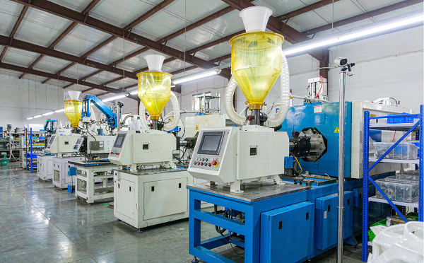
If you are here because someone mentioned Xiamen Goldcattle, this is the page that answers the practical question: are we a real factory, what can we actually mould, how do we build and validate the tool, who owns it, and what does it cost in time and money? We do not repeat general injection molding theory here — that lives on our injection molding services page. This page is the supplier record.
On This Page
Goldcattle Injection Molding at a Glance
The twelve questions a buyer asks before sending a CAD file — answered in one table.
| Buyer Question | Goldcattle |
|---|---|
| Location | Xiamen, Fujian, China |
| Legal entity | Xiamen Goldcattle Plastic & Metal Products Co., Ltd. — the single legal name used on this site, in our documentation and in our quality records |
| Business type | Factory-based custom manufacturer. All six core processes — injection molding, mold making, CNC machining, 3D printing, die casting and sheet metal fabrication — are performed in-house under one ISO 9001:2015 quality system |
| Service | Custom plastic injection molding: DFM, tooling, T1 validation, production molding, inspection and secondary operations |
| Tooling | In-house mold engineering and mold build — design, steel, CNC, EDM, fitting and assembly |
| Volume | Prototype · bridge · low volume · mass production |
| Materials | Commodity and engineering thermoplastics, including glass-filled grades and high-performance resins. Final resin selection is confirmed per application |
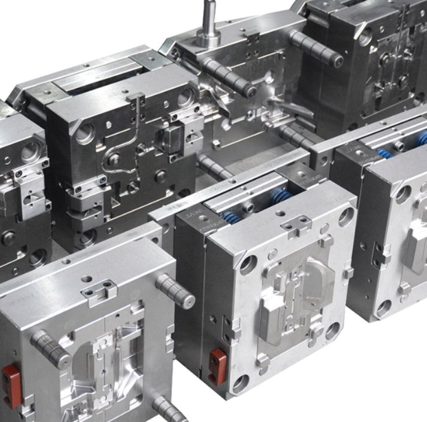
| Mold types | Single-cavity, multi-cavity, family molds, insert molding, overmolding and two-shot tools |
| Secondary operations | Finishing and assembly available; scope agreed per programme |
| Quality system | ISO 9001:2015 certified. Inspection scope, documentation and traceability are agreed per project rather than assumed |
| Quotation inputs | 3D CAD, 2D drawing, resin preference, annual volume and target timeline |
| Target markets | North America and Europe, plus other export markets |
Most supplier pages answer "what is injection molding". Very few answer "what will you actually do with my part, my tool and my volume". If you are comparing two or three moulders, the twelve rows above are the ones worth putting side by side.
Who Is Xiamen Goldcattle as an Injection Molding Supplier?
Founded in 1998 in Xiamen, Fujian — a factory, not a trading office with a catalogue.
Xiamen Goldcattle Plastic & Metal Products Co., Ltd. is an OEM/ODM manufacturer founded in 1998. Injection molding is one of six processes we run ourselves, and that detail matters more than it first appears.
A moulder that only moulds has to buy its tooling elsewhere. When a tool comes back late, or a gate needs moving, or a cavity has to be re-cut after T1, the moulder is waiting in someone else's queue. Because mold making sits in the same building under the same quality system, tooling changes are an internal engineering task rather than a purchase order. In practice this shortens the loop between "the sample does not fill" and "the tool is modified".
It also changes what we can tell you honestly. When we quote a tooling lead time, we are quoting our own machine shop's schedule. When we say a part needs a side-action, we are the people who would have to build it.
The other consequence of running six processes is that we have no commercial interest in forcing your part into molding. If your annual volume does not justify tooling, or your geometry is better machined, that answer costs us nothing to give — we also run CNC machining, 3D printing, die casting and sheet metal in-house.
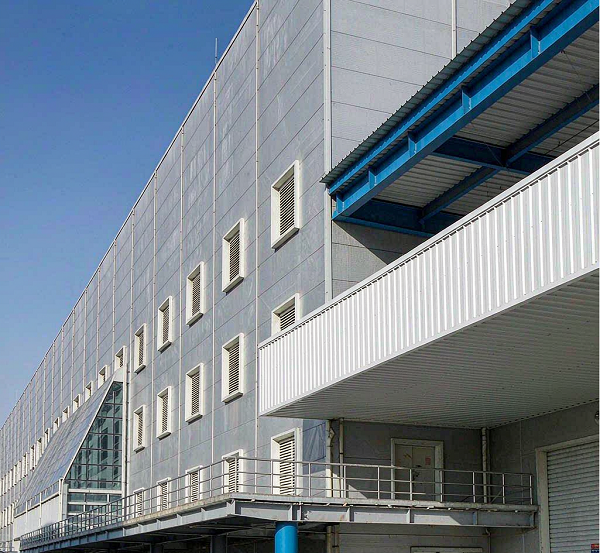
Our legal entity name is Xiamen Goldcattle Plastic & Metal Products Co., Ltd. This is the single name used on this page, in our quality documentation, on our certificates, in our structured data and in our quotations. If you encounter a different company name attached to our brand on a directory listing, a marketplace profile or a document, ask us to confirm it in writing before you rely on it — entity name consistency is exactly what a supplier approval process should check.
Our Injection Molding Capabilities
Nine distinct tooling and molding routes — each one exists because a specific commercial situation makes the others wrong.
A "we do injection molding" statement tells a buyer nothing. What matters is which tooling strategy fits your volume, your design stability and your unit-cost target, and what each strategy costs you in lead time and flexibility. These are the nine routes we run, and the honest case for and against each.
Rapid Tooling
Aluminium or soft-steel tooling built to get real parts in your hands fast — for design validation, fit checks, market testing and bridge production while the production tool is being built.
- Fastest route to moulded parts in the production-intent resin
- Tool modifications are cheap and quick
- Cavity count and cooling are usually simplified
- Expected shot life is stated per tool, per resin and per geometry before you commit
Production Tooling
Hardened tool steel, proper cooling circuits, hardened slides and lifters, and a tool built for a defined service life rather than for a first shot.
- Steel grade and hardness selected against your annual volume and resin
- Cooling layout designed for cycle time and dimensional stability
- Higher upfront investment, amortised over volume
- The correct choice once the design is frozen
Multi-Cavity Molding
More than one identical cavity per tool. Output per cycle multiplies, so the machine and labour cost per part falls — provided the cavities actually fill identically.
- Cavity-to-cavity balance is the engineering problem, not the cavity count
- Naturally balanced runner layout, or a balanced hot runner system
- Cavity identification lets you trace a defect to one cavity
- Tool cost rises roughly with cavity count; unit cost falls
Family Molds
Several different parts — typically the components of one assembly — in a single tool. One machine cycle produces a kit.
- One tool, one setup, one run: lower cost than several separate tools
- Fill behaviour differs between cavities; balance is harder
- If one cavity is damaged or modified, the whole tool stops
- Best when part sizes and shot volumes are comparable
Insert Molding
A metal insert — threaded bushing, contact, terminal, machined bracket — is placed in the tool and encapsulated by the plastic shot.
- Eliminates a post-moulding assembly or heat-staking step
- Insert placement repeatability drives cycle time and scrap
- Insert needs positive location so it cannot shift under injection pressure
- Automation is justified once volume covers the placement mechanism
Overmolding
A second, softer material — usually TPE or TPU — moulded onto a rigid substrate to produce a grip, a seal or a shock-absorbing surface.
- Bonding may be chemical (material compatibility) or mechanical (undercuts, through-holes)
- Substrate and overmould resin pair must be validated, not assumed
- Substrate shrinkage and heat resistance set the process window
- We confirm the material pair before tooling is committed
Two-Shot / 2K Molding
Two materials or two colours in one machine cycle, using a rotary or transfer mechanism. The part leaves the machine finished.
- Strongest bond, because the second shot meets a still-warm substrate
- Requires a two-shot capable machine and a considerably more complex tool
- Highest tooling investment of the multi-material routes
- Economical at volume; overkill for a short run
Thin-Wall Molding
Housings, enclosures, packaging and electronic parts where wall sections are reduced to save material, weight and cycle time.
- Requires high injection speed and pressure; not every machine is suitable
- Fill is dominated by flow length ratio — gate position becomes critical
- Venting and warp control decide whether the part is usable
- Rib design must avoid sink marks on the opposite face
Precision / Micro Molding
Connectors, small mechanical components and parts where the tolerance is demanding relative to the part size.
- Tooling accuracy and measurement method matter more than machine tonnage
- Shrinkage is resin-specific and fibre-orientation dependent
- Achievable tolerance is stated per feature after DFM review, not per material
- Inspection method agreed with you before the tool is cut
Capability Is Not the Same as Suitability
Having nine routes does not mean every part should be moulded. Thin-wall is the wrong answer for a part that will see impact loading; two-shot is the wrong answer for a 500-piece run; a family mould is the wrong answer when one component of the set is still changing design.
We would rather route your part to the correct process — including CNC machining or 3D printing, both of which we also run in-house — than quote a tool that will frustrate you by T1. See when injection molding may not be the best choice for the specific cases.
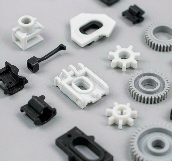
Injection Molding Equipment & Production Capacity
What we can state publicly, what we confirm per programme, and what we will put in writing for your supplier approval file.
Equipment claims are the easiest thing for a supplier page to inflate and the hardest thing for a buyer to check. Our approach is deliberately narrow: we publish what is stable and verifiable, and we confirm anything programme-specific directly, in writing, when you ask.
| Capability | What We Can State | Basis |
|---|---|---|
| Machine count | Part of the 100+ machines operating across our six in-house processes. The injection molding allocation changes with the production mix. | Current moulding machine count confirmed with your RFQ |
| Machine tonnage | Matched to part projected area and shot weight rather than quoted as a single generic band. | Confirmed per part — send the model and we name the machine |
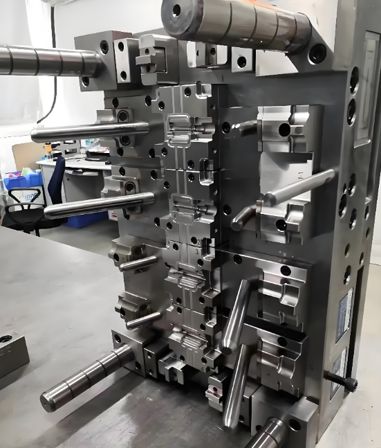
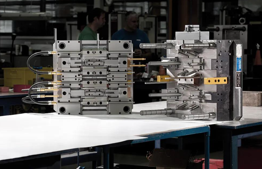
| In-house tooling | Yes. Mold engineering, mold design, CNC machining, EDM and mold assembly are performed in-house. | Published capability |
| Materials processed | Commodity and engineering thermoplastics, glass-filled grades, TPE/TPU, and high-performance resins including PEEK. | Published capability |
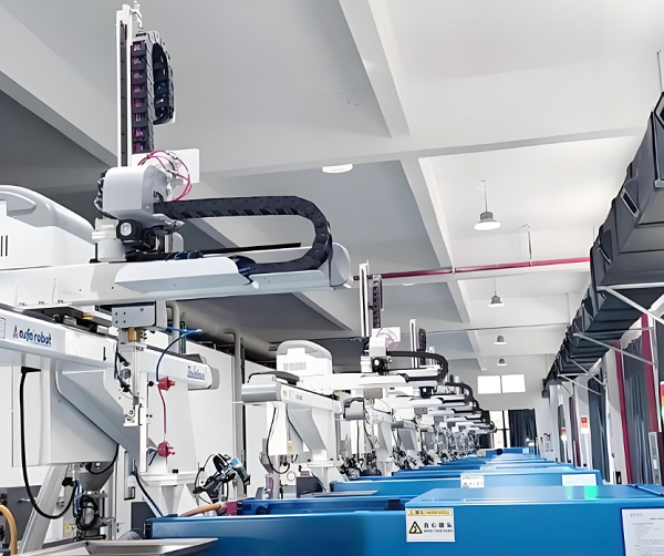
| Automation | Robot take-out and conveyor handling are used where cycle time and volume justify them. | Scope agreed at quotation, per part |
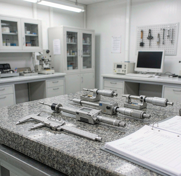
| Inspection | Dimensional inspection performed in-house with calibrated equipment. | Equipment list available on request |
| Production scheduling | Programme-dependent, set against tooling readiness and your delivery schedule. | Confirmed per programme |
| Quality system | ISO 9001:2015 certified. | Certificate copy available on request |
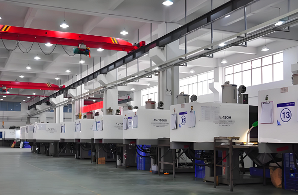
Machine Range
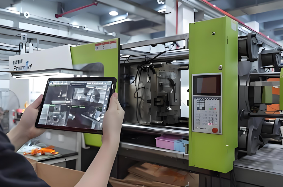
Clamp force is not a prestige number — it is a function of your part's projected area and the cavity pressure the resin and wall thickness will generate. A machine that is too small flashes; a machine that is far too large wastes energy and can make small shots harder to control. Because the right answer is part-specific, we size the machine from your model and tell you which press your part will run on, rather than quoting a headline range that does not apply to your geometry.
The related constraint is shot capacity and tie-bar spacing: a part can be within tonnage and still not fit between the tie bars, and a multi-cavity tool needs the platen area to carry it.
Automation
Automation is a commercial decision, not a badge. A robot take-out makes sense when it removes operator variability, protects a delicate part, or stabilises a cycle that would otherwise depend on manual removal. It does not make sense on a 300-piece bridge run where the setup time exceeds the benefit. We state whether your part will run automated at quotation, along with what that does to tooling cost and cycle time.
In-House Tooling
This is the single most consequential equipment question for a buyer, and the one most often dodged. We build our own molds: design, steel procurement, CNC milling, EDM, wire cutting, fitting, assembly and tryout happen in our own toolroom. The practical effects are that tooling lead time is a schedule we control, tool modifications are an internal job, and the engineers who design the tool are the ones who see it run at T1.
Inspection Capability
Dimensional inspection is performed in-house. What we will not do is imply that every part receives a full dimensional report — that would be untrue for us and for most moulders. The inspection scope — which features, at what frequency, to which method, and with what record — is agreed with you before production and priced accordingly. If you need full inspection on a critical feature, ask for it and it will be quoted.
If you are qualifying us as a supplier, ask for any of the following and we will provide current documents rather than marketing copy:
- Current injection moulding machine list with tonnage
- ISO 9001:2015 certificate copy, with certificate number and validity
- Inspection equipment list and calibration status
- Blank first article inspection report template
- Sample dimensional inspection report from a comparable programme
- Mold design output format (2D and 3D) and steel certification practice
- Production flow chart from goods-in to despatch
From CAD to Delivered Plastic Parts
Fifteen stages, each with a defined input, an action and an output — so you always know what happens next and what you are being asked to approve.
Most supplier pages describe the molding cycle: clamp, inject, cool, eject. That is a machine sequence, not a procurement process. What a buyer actually needs is the sequence of decisions and approvals between sending a file and receiving production parts — and, critically, which of those steps they own.
| Stage | Input | What We Do | Output | Your Sign-Off |
|---|---|---|---|---|
| CAD / Drawing Intake | 3D model (STEP / IGES), 2D drawing, sample if available | Check model integrity, units, datum structure and drawing completeness | Confirmed technical package | Yes — confirm the revision |
| Engineering Review | Confirmed package, annual volume, target markets | Assess manufacturability, process route and commercial fit | Process recommendation and budgetary indication | — |
| DFM Analysis | Model, resin, critical features | Report wall thickness, draft, ribs, bosses, gate and ejector options, sink and warp risk | DFM report with recommended changes | Yes — approve or reject changes |
| Material Selection | Application conditions, regulatory needs, target cost | Shortlist resins against load, temperature, chemical exposure, and compliance | Recommended resin with rationale | Yes — final resin confirmation |
| Mold Design | Approved DFM, resin, cavity count decision | Design cavity/core, runner, gating, cooling, ejection and venting | Mold design for approval | Yes — design approval |
| Tooling Build | Approved mold design | Steel procurement, CNC, EDM, wire cut, fitting, assembly | Completed mold, ready for trial | — |
| T0 / T1 Trial | Completed mold on a production machine | Internal trial (T0), then first formal shot (T1) with process parameters recorded | T1 samples and trial parameters | — |
| Sample Inspection | T1 samples, drawing, agreed inspection scope | Measure agreed features; record appearance and function checks | Inspection report | Yes — sample approval |
| Process Validation | Approved samples and parameters | Confirm the process window that produces conforming parts repeatably | Documented process parameters | — |
| Production | Validated process, released schedule | Run to order quantity against the validated parameters | Production parts | — |
| In-Process QC | Production run, control plan | Check critical features at the agreed frequency | In-process records | — |
| Final Inspection | Finished lot | Inspect to the agreed scope and accept/reject criteria | Final inspection record | — |
| Secondary Operations | Molded parts, finishing or assembly requirement | Deflashing, surface treatment, printing, assembly, packing to spec | Finished goods | Yes — where specified |
| Packaging | Finished goods, packing specification | Pack to your carton, labelling and pallet requirements | Packed, labelled pallets | — |
| Delivery | Packed order, Incoterms | Coordinate export documentation and shipment | Shipped order with documents | — |
DFM Analysis
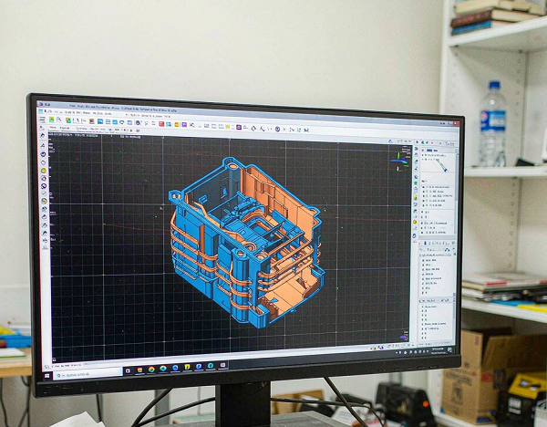
DFM is the highest-value stage in the whole programme and the one most often skipped because it costs time before anything visible happens. It is where a wall section that will sink, a boss that will crack, or a draft angle that will scuff gets found — while the fix is a model edit rather than a steel modification.
Our DFM report covers wall uniformity, draft on all vertical faces, rib-to-wall ratios, boss design, gate location options and their cosmetic consequence, ejector placement and the marks it leaves, venting at the last-fill area, and shrinkage-sensitive dimensions. We tell you what we would change and why. You decide whether to change it.
Mold Design
Mold design is where the commercial decisions get locked in: cavity count sets output and unit cost; runner type sets material waste and balance; cooling layout sets cycle time; steel grade sets tool life and therefore which volume the investment is amortised against. We present these as decisions with consequences, not as defaults you discover later.
Tooling Build
Because the toolroom is ours, the build schedule is one we control directly. Steel is procured against the agreed specification, cavity and core are machined and finished, slides and lifters are fitted, cooling circuits are pressure-tested, and the tool is assembled and checked before it goes near a moulding machine.
T0 / T1 Trial
T0 is our internal trial — we run the tool ourselves first and correct what we find. T1 is the first formal shot that produces the samples you receive. Confusing the two is how buyers end up receiving "first samples" that are really a debugging exercise. With us, what you receive at T1 has already been through internal correction, and the process parameters used are recorded so that production can reproduce them.
Production & In-Process QC
Production runs against validated parameters. In-process checks target the features that matter for fit and function, at a frequency agreed with you. This is a sampling and control approach, not a promise that every dimension on every part is measured — and we would rather say that plainly than imply something we cannot staff.
Secondary Operations
Deflashing, surface treatment, pad printing, ultrasonic welding, heat staking, insertion of hardware and sub-assembly can be carried out after molding. Every secondary operation adds handling, cost and a potential failure mode, so we quote it separately and only when it is actually needed.
Packaging & Delivery
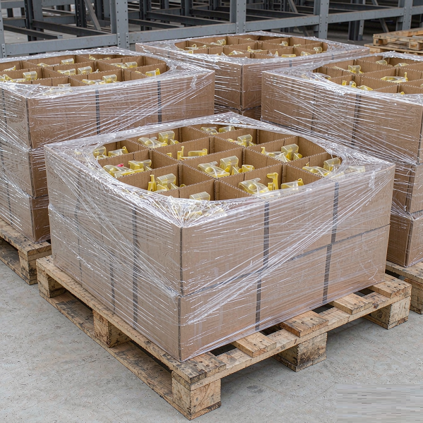
Packing is specified, not improvised: carton size, parts per carton, protection against scuffing, labelling and pallet configuration are agreed before the first production run. Export documentation and Incoterms are confirmed at quotation so that landed cost is not a surprise.
Prototype, Low-Volume and Mass Production
The right manufacturing process changes as volume, design stability and unit-cost pressure change. One part can legitimately travel through all four routes.
Prototype
The design is still changing, and the point is to learn something — about fit, about feel, about whether an assembly closes. Tooling at this stage is a liability, because every design change becomes a steel change.
- Best route: CNC machining or 3D printing, both in-house
- Moulded prototypes are viable when the resin behaviour itself is what you need to test
- Quantity is usually single digits to low tens
- Lead time is measured in days, not weeks
Bridge Production
The design is close to final, but the production tool is not ready or not yet justified. You need real parts in real material, in quantities larger than a prototype run, to support pilot builds, customer sampling or regulatory work.
- Best route: rapid or soft tooling — aluminium or soft steel, simplified cooling
- Parts are in the production-intent resin, which is the whole point
- Expected shot life is stated per tool, per resin and per geometry before you commit
- Keeps your programme moving while the hardened tool is built
Low Volume
Demand is real but modest, or the product is one of many variants. A high-cavity hardened tool would take years to pay back, but machining every part is too slow or too expensive.
- Best route: low-cavity tooling, often single or two-cavity, in a steel grade matched to the realistic lifetime volume
- Simpler tool, lower investment, higher unit cost
- Flexible when variants share a base tool
- The honest break-even point should be calculated, not guessed
Mass Production
The design is frozen, volume is forecastable, and unit cost dominates. Tooling becomes an investment with a payback calculation attached.
- Best route: multi-cavity hardened steel tooling, automation where justified
- Steel grade and cooling design driven by target shot life
- Cavity count set against annual volume and machine availability
- Highest upfront cost, lowest unit cost
Commissioning a production tool before the design is stable. The tool is the only thing in the programme that cannot be updated with a file transfer. If a dimension is still moving, prototype first — we will say so at quotation even though it delays the tooling order.
Injection Molding Materials
Not a material encyclopaedia — a selection guide organised around why a buyer picks each resin and what that choice costs elsewhere.
Resin selection is a compromise between mechanical performance, processing behaviour, regulatory position and price. The tables below give you the decision logic; the final choice should be made against your actual service conditions.
| Resin | Why Buyers Choose It | Typical Applications | What to Watch |
|---|---|---|---|
| PP (Polypropylene) | Low density, chemical resistance, fatigue resistance on living hinges, low material cost | Automotive interior, consumer goods, packaging, living-hinge closures | Higher shrinkage; poor dimensional stability under load at temperature; bonding and painting need treatment |
| ABS | Good stiffness-impact balance, excellent surface finish, easy to paint and plate | Housings, bezels, appliance panels, consumer enclosures | Limited chemical and UV resistance; not suitable for high-temperature service |
| PC (Polycarbonate) | High impact strength, transparency, heat resistance | Electronic housings, transparent covers, lighting, safety components | Notch-sensitive; stress cracking with certain chemicals; requires thorough drying before processing |
| PA (Nylon, incl. GF) | Strength, wear resistance, fatigue resistance; glass-filled grades add stiffness | Structural brackets, gears, mechanical components, under-hood parts | Moisture absorption changes dimensions; glass fibre causes anisotropic shrinkage and warp |
| POM (Acetal) | Low friction, good dimensional behaviour, fatigue resistance | Gears, bearings, sliding mechanisms, precision mechanical parts | Shrinkage is significant and crystalline; tight tolerances need process control |
| PEEK | High-performance engineering resin: temperature, chemical and wear resistance | Demanding components in aerospace, semiconductor, medical and industrial service | High material cost; requires high processing temperatures and specialised tooling considerations |
| TPE / TPU | Soft, flexible, elastic; bonds to rigid substrates in overmolding | Grips, seals, overmoulded handles, flexible connectors | Shore hardness selection drives both feel and tooling; substrate compatibility must be validated |
| PMMA (Acrylic) | Optical clarity, scratch resistance, weathering | Lenses, light guides, transparent panels | Brittle relative to PC; notch-sensitive |
How We Approach Resin Selection
We start from the service conditions, not from a datasheet comparison. Six questions decide most selections:
- Temperature — continuous and peak, under load
- Chemical exposure — oils, cleaners, solvents, body fluids
- Mechanical load — static, impact, cyclic, wear
- Dimensional requirement — which features are critical, and over what humidity and temperature range
- Regulatory requirement — food contact, RoHS, REACH, flame rating, or a medical-grade position
- Target cost — resin price plus the processing cost the resin imposes through cycle time and tool wear
That last point is the one buyers most often miss. A cheaper resin that needs a 40-second cycle can cost more per part than an expensive resin that runs in 22 seconds, once machine time is included. We compare resins on cost per acceptable part, not cost per kilogram.
Adding glass fibre raises stiffness and strength but makes shrinkage directional. Fibres align with flow, so the part shrinks differently along and across the flow path — which is the usual origin of warpage in a flat, ribbed component. If you are switching an unfilled resin to a filled grade, the tool may need gate relocation, and the tolerances you achieved before may not carry over. We flag this at DFM rather than at T1.
Injection Molding Quality Control
Eight control points, what is actually checked at each, and what record you receive.
"Quality is our lifeline" is not a quality system. A quality system is a list of control points, a defined check at each one, and a record that lets you trace a problem back to a batch. Here is ours.
| Control Point | What Is Checked | What You Receive |
|---|---|---|
| Incoming material | Resin identification against the purchase specification; packaging and lot integrity; inserts checked to drawing where supplied | Material lot record |
| Material verification | Grade confirmation against the specification; certificate review where the programme requires it | Certificate reference where applicable |
| Mold validation | Cavity and core condition, slide and lifter function, cooling circuit integrity, ejection | Tool status before trial |
| First article inspection | Agreed features measured on T1 samples; appearance and function checks | First article inspection report |
| In-process inspection | Critical features at an agreed frequency; process parameters monitored | In-process records |
| Final inspection | Dimensions, appearance and function against the agreed accept/reject criteria | Final inspection record |
| Documentation | Records assembled and retained per the programme requirement | Documentation package as agreed |
| Traceability | Linkage between part lot, material lot and production record, where the programme requires it | Traceability record on request |
Material Verification
Resin is verified against the specification before it goes into a hopper. Where a programme requires documented evidence — a certificate of analysis, a RoHS declaration, a specific grade certification — that requirement is captured at quotation so it can be sourced with the material rather than retrofitted afterwards.
Mold Validation
Before a tool runs for samples, it is checked mechanically: slides and lifters move freely, cooling circuits hold pressure, ejection returns fully, and cavity and core surfaces are in the condition they should be. A tool that has not been validated produces samples that tell you nothing reliable.
First Article Inspection
FAI is the formal measurement of the first parts off the tool against the drawing, covering the features agreed in advance. It is the moment where "the tool works" becomes "the tool makes parts to the drawing". We share the report and wait for your approval before scheduling production.
In-Process Inspection
During a run, checks target the features that govern fit and function, at a frequency agreed with you. This is a control strategy, not a blanket commitment to measure everything — and we would rather define it honestly than promise full inspection we cannot sustain on a production-priced part.
Final Inspection
Final inspection applies the accept/reject criteria agreed at quotation: which dimensions, which cosmetic standard, viewed from what distance and under what lighting. Cosmetic criteria are worth defining in writing — "no visible defects" means different things to different people.
Traceability
Where a programme requires lot-level traceability — linking finished parts back to material batch, machine and production date — we set that up as part of the quality agreement. It is confirmed on a project-by-project basis rather than assumed for every order, because the record-keeping it requires has to be built into the production routine from the first run.
We hold ISO 9001:2015 certification. We support IATF 16949 requirements and ISO 13485-aligned process controls where a programme calls for them, and we will state plainly which applies to your project. We do not claim certifications we do not hold. RoHS and REACH are material compliance declarations — they are not a quality management system and should not be presented as one. If your approval process needs current certificate copies with numbers and validity dates, ask and we will send them.
Tool Ownership, NDA & IP Protection
The questions buyers are often reluctant to ask, answered before you have to ask them.
Tooling represents a significant capital item that physically sits in someone else's building. That is an uncomfortable position if the terms were never made explicit — and a completely normal one if they were.
Mold Ownership
Tooling built for your programme is customer-owned. You paid for it; it is identified as yours, and it is used for your programme. This is stated in the quotation, not buried in a footnote.
NDA & CAD Confidentiality
We are able to sign a mutual NDA before you release files. CAD data is held within the engineering group working on your programme, and project files are not used for marketing or shown to other customers without written permission.
Tool Storage & Maintenance
Molds are stored in our toolroom when not in production, identified and logged. Routine maintenance — cleaning, lubrication, inspection of slides and cooling circuits — is carried out so the tool is ready to run when you reorder.
Tool Transfer
Because the tool belongs to you, it can be transferred — to you directly or to another moulder you nominate. We will release it and provide the design data that goes with it.
A moulder who is vague about tool ownership is telling you something. Make it a standard question with every supplier you evaluate: who owns the mold, where is it stored, who maintains it, and can it be moved? If the answer takes more than one sentence, that is the answer.
What Determines Injection Molding Cost?
Eight variables that move the number — and which ones you actually control.
| Factor | Why It Moves the Price | What You Can Influence |
|---|---|---|
| Mold complexity | Slides, lifters, unscrewing mechanisms and conformal cooling add design and machining hours | Geometry simplification during DFM — often the single biggest lever |
| Cavity count | Sets tooling investment and output per cycle, therefore unit cost | Realistic volume forecast; over-specifying cavities ties up capital |
| Material | Resin price per kilogram, plus cycle-time and tool-wear consequences | Grade selection against real service conditions, not worst-case assumptions |
| Annual volume | Determines how fast tooling amortises | Committed annual quantity rather than per-order quantity |
| Surface finish | Textured, polished or optical finishes require specific steel and additional handwork | Specify texture only where it is visible or functional |
| Tolerance | Tighter tolerances require more process control and more inspection | Tolerance only the features that affect fit and function |
| Secondary operations | Each added step adds handling, labour and a defect opportunity | Design assembly features into the moulding where possible |
| Automation | Higher upfront mechanism cost against lower running cost and less variability | Volume and part delicacy decide it; we will tell you if it is not worth it |
Trap one: comparing tooling quotes without comparing cavity count, steel grade and expected shot life. A cheaper tool that produces half the output per cycle and half the service life is not cheaper.
Trap two: tolerancing every dimension as critical. Global tight tolerances push a part from a standard process into a controlled one, and you pay for that in inspection time and scrap. Mark the five features that matter and let the rest be standard.
What Determines Injection Molding Lead Time?
Tooling lead time and production lead time are two different clocks. Conflating them is the most common source of a missed launch.
When a buyer asks "how long does injection molding take", the answer depends entirely on whether the tool exists. Before the tool exists, the clock is dominated by mold design and build. After the tool is validated, the clock is dominated by scheduling and quantity. These are different processes with different durations, and a supplier who gives you one number for both is hiding the detail.
DFM and Engineering Review
Duration depends on how much the design needs to change, and on how fast your team responds to questions.
Mold Design
Complexity-driven: cavity count, slides, lifters and cooling layout all add design time. This stage ends with your design approval.
Steel and Components
Procurement of the specified steel grade and standard mold components — a real calendar item, not an internal task.
CNC Machining and EDM
The longest single block in the tooling schedule, driven by cavity complexity and surface finish requirement.
Mold Assembly and Fitting
Slides, lifters, ejection and cooling fitted and checked by hand.
T0 / T1 Trial
Internal trial first, then the formal first shot. The number of iterations depends on the part.
Sample Inspection and Your Approval
This is the stage most often left out of supplier estimates — and it is on your side of the fence.
Mold Modification (if required)
Steel modification after sample feedback adds a second machining cycle. Good DFM reduces the chance of needing it.
Production Scheduling and Run
Once the tool is released, production lead time depends on order quantity and the current schedule.
We separate tooling lead time from production lead time in every quotation, and we identify the approval gates that sit on your side. That way a schedule slip is attributable rather than mysterious. Specific durations are quoted per project after DFM review — a generic number published on a page would not survive contact with your geometry.
Injection Molding Case Studies
Three representative programme types, described by engineering problem and approach rather than by headline numbers.
These are representative programme types drawn from the kind of work we run. They are anonymised — no customer names, part numbers or measured performance figures — because we do not publish customer-identifying information or results without written permission. What we can do is walk you through the engineering reasoning, and put you in touch with references where that is permitted.
Thin-Wall Enclosure for a Handheld Device
- Customer need
- A light, rigid enclosure for a portable electronic device, with a cosmetic outer surface and internal snap-fits.
- Part
- Two-part clamshell enclosure, wall sections reduced for weight and material saving.
- Resin
- ABS selected for surface finish and paintability; confirmed against drop and temperature requirements.
- Mold
- Production tooling in hardened steel, single-cavity per half with polished cavity surfaces.
- Key challenge
- Filling thin sections over a long flow length without short shots or visible weld lines, and keeping the cosmetic face free of sink marks opposite internal ribs.
- DFM solution
- Gate relocated to balance fill and move the weld line away from the cosmetic face; rib thickness reduced relative to the nominal wall to avoid sink; venting added at the last-fill area; draft increased on the cosmetic wall to prevent scuffing on ejection.
- Production
- Validated process parameters recorded at T1 and reproduced for production runs.
- Quality control
- Snap-fit dimensions and flatness inspected on first articles; cosmetic criteria agreed in writing before production.
- Result
- Parts released to production against the drawing, with the cosmetic standard documented so that later reorders were judged against the same criteria.
Glass-Filled Structural Bracket
- Customer need
- A load-bearing bracket where the original design was machined from aluminium, to be converted to moulded plastic for weight and cost.
- Part
- Ribbed structural bracket with metal threaded inserts at the mounting points.
- Resin
- Glass-filled PA selected for stiffness and strength; chosen against load case and service temperature.
- Mold
- Single-cavity production tool with hardened slides and insert loading provisions.
- Key challenge
- Glass fibre makes shrinkage directional, so a flat, heavily ribbed part tends to warp. Insert placement also had to stay accurate under injection pressure.
- DFM solution
- Rib layout reviewed for uniform wall and balanced orientation; gate position set to manage fibre orientation and warp direction; insert bosses designed with positive location features; steel and cooling selected for the abrasive filled resin.
- Production
- Insert loading method agreed before tooling, with cycle-time impact priced openly.
- Quality control
- Mounting-point geometry and flatness measured on first articles; insert pull-out performance checked against the requirement.
- Result
- A moulded part that met the load requirement at lower weight and unit cost than the machined original, produced in the same tool across repeat orders.
Two-Material Soft-Grip Handle
- Customer need
- A hand tool handle combining a rigid structural body with a soft, non-slip grip surface.
- Part
- Rigid substrate overmoulded with a soft elastomer in defined grip zones.
- Resin
- Rigid engineering substrate paired with a TPE in a specified Shore hardness.
- Mold
- Overmolding tooling with substrate location designed to prevent movement during the second shot.
- Key challenge
- Adhesion between the two materials, and keeping the boundary between hard and soft zones visually clean and consistently placed.
- DFM solution
- Substrate and TPE pair validated for compatibility before tooling; mechanical interlocks added so bonding did not rely on chemistry alone; shut-off geometry defined to hold a crisp material boundary; gate position chosen to keep flow away from the visible boundary.
- Production
- Process window established to hold adhesion within the cycle time required.
- Quality control
- Adhesion checked on first articles and monitored; boundary appearance inspected against an agreed cosmetic sample.
- Result
- A finished two-material part leaving the moulding cell without a secondary bonding or assembly operation.
How to Evaluate an Injection Molding Supplier
Ten questions worth asking every moulder you are considering — including us — and our answer to each.
The point of this section is not to flatter us. It is that these ten questions separate a factory from a broker, and a controlled process from a hopeful one. Use them on every quote you are comparing.
| Question | Why It Matters | Goldcattle's Answer |
|---|---|---|
| 1. Do they build molds in-house? | Determines who controls tooling lead time and who can modify the tool after T1. | Yes — mold design, steel, CNC, EDM, fitting and assembly in our own toolroom. |
| 2. Do they provide DFM before tooling? | The cheapest place to fix a part is the model, not the steel. | Yes, on every tooling programme, with a written report and your approval before steel is cut. |
| 3. Can they show T1 samples and the inspection record? | Samples without measurement tell you the tool runs, not that the parts conform. | T1 samples are measured against agreed features and the report is shared for your approval. |
| 4. Who owns the mold? | A capital asset sitting in someone else's building needs explicit terms. | Customer-owned. Identified, stored, maintained, and transferable on request. |
| 5. How is quality measured, and how often? | "Checked" is not a method. Frequency and features must be defined. | Inspection scope, features, frequency and records agreed per project before production. |
| 6. Can they provide inspection documentation? | You may need it for incoming inspection, audit or regulatory files. | FAI reports, in-process records and final inspection records available as agreed. |
| 7. What materials can they actually process? | Some moulders are set up for a narrow resin range; filled and high-temperature resins need experience. | Commodity through engineering thermoplastics, glass-filled grades, TPE/TPU and PEEK. |
| 8. What volume range can they handle? | A shop optimised for mass production is often poor at bridge volumes, and vice versa. | Prototype, bridge, low volume and mass production, with the route chosen to match your stage. |
| 9. What secondary operations are available? | Finishing and assembly affect cost, lead time and defect exposure. | Deflashing, surface treatment, printing, welding, hardware insertion and assembly, quoted per programme. |
| 10. How is IP protected? | Your CAD is the asset. Its handling should be explicit. | NDA available before file release; project files restricted and never used for marketing without permission. |
Why Source Injection Molding From Xiamen, China?
The reasons are logistical and industrial, not scenic.
Xiamen is on the south-east coast of Fujian, and the reasons a moulded part supply chain clusters there are practical ones:
Manufacturing Ecosystem
Tool steel suppliers, mold component makers, EDM and wire-cutting subcontractors, resin distributors and surface-treatment shops are all within short distance. When a programme needs a non-standard component or a specialist surface treatment, it is sourced locally rather than shipped across the country — which compresses the tooling schedule in a way that a low quotation from an isolated factory cannot replicate.
Port Connectivity and Export Logistics
Xiamen is a major container port with regular services to North America and Europe. For a moulded part programme, the practical effect is predictable transit and a choice of sailings, which matters far more than a marginally cheaper inland factory with a longer, less frequent route to the coast.
Multi-Process Concentration
Many programmes need more than molding — a machined insert, a die-cast bracket, a sheet metal chassis, a printed prototype before the tool. Having those processes in the same industrial region, and in our case in the same factory, removes interface risk between suppliers.
Engineering and Toolmaking Depth
The region has a deep bench of mold designers and toolmakers. Tooling is still a skilled trade, and the difference between a well-fitted tool and a poorly fitted one shows up in flash, in cycle time and in how many iterations T1 takes.
Why Goldcattle Specifically
- Six processes under one roof and one quality system. Injection molding, mold making, CNC machining, 3D printing, die casting and sheet metal fabrication are all performed in-house — so process recommendations are not steered by what we happen to own.
- Tooling built by the people who run it. Our toolroom designs, builds and tries out the mold. Tool modifications after T1 are an internal engineering task instead of a purchase order.
- DFM before quotation is final. You see what we would change and why, and you approve it before steel is committed.
- Tooling and production lead time quoted separately. No single vague number, and your approval gates are identified as calendar items.
- Customer-owned tooling, stated in writing. Identified, maintained, stored and transferable.
- Certifications stated accurately. ISO 9001:2015 certified; IATF 16949 and ISO 13485 alignment described as support and alignment, not as claims we cannot substantiate. Current certificate copies available on request.
When Injection Molding May Not Be the Best Choice
Four situations where we will tell you to use a different process — including ones we also run.
A supplier who says yes to everything is not giving you engineering advice. These are the cases where we would steer you elsewhere.
You Need One Part, Once
If the requirement is a single unit for a fit check or a design review, a mold is the wrong instrument. CNC machining or 3D printing will deliver it sooner and cheaper, and we run both in-house. Molding becomes rational when you need several parts, or when you specifically need the part in the production resin.
The Design Is Still Moving
Tooling freezes geometry. If critical dimensions are still under discussion, commissioning a production tool converts every future design change into a steel modification with a cost and a delay attached. Prototype first, freeze the design, then tool — in that order.
The Volume Cannot Amortise the Tool
Tooling is a fixed cost that has to be recovered across the number of parts you will actually make. Below a certain quantity, machining each part is simply cheaper, and any honest moulder will do that arithmetic with you rather than sell you a tool you do not need.
The Geometry Exceeds the Machine Envelope
Very large parts require clamp force and platen area that may exceed what is available or economic. Before we quote, we check the projected area and the machine fit. If your part is outside a sensible envelope, we will say so and discuss alternatives rather than quote a tool we cannot run.
In all four cases there is usually a better answer available in-house: CNC machining for low quantities and tight features, 3D printing for form and fit studies, or prototype tooling when you need moulded parts but not yet a production tool. We would rather place your part on the right process and keep the relationship than sell a tool that disappoints.
Frequently Asked Questions
Supplier qualification questions, not "what is injection molding" questions.
Xiamen Goldcattle Plastic & Metal Products Co., Ltd. is based in Xiamen, Fujian, on the south-east coast of China. The factory operates injection molding and mold making alongside CNC machining, 3D printing, die casting and sheet metal fabrication, and ships to customers in North America, Europe and other export markets.
Yes. Mold engineering, mold design, CNC machining, EDM, wire cutting, fitting and assembly are performed in our own toolroom. This is why we can quote tooling lead time as a schedule we control, and why tool modifications after T1 are an internal engineering task rather than a subcontracted purchase order.
On every tooling programme. The DFM report covers wall uniformity, draft, rib and boss proportions, gate and ejector options, venting, and shrinkage-sensitive features. You approve or reject the recommended changes before steel is committed.
Commodity and engineering thermoplastics including PP, ABS, PC, PMMA, PA (nylon, including glass-filled grades) and POM, elastomers including TPE and TPU, and high-performance resins such as PEEK. Final resin selection should account for temperature, chemical exposure, mechanical load, dimensional requirements, regulatory needs and target cost — we shortlist against your actual service conditions.
Prototype, bridge production, low volume and mass production. The route is matched to your design stability and volume: machining or printing while the design moves, soft tooling for bridge quantities, low-cavity tooling for modest demand, and multi-cavity hardened tooling with automation where the volume justifies it.
Yes. Rapid tooling in aluminium or soft steel is used for design validation, market testing and bridge production while a hardened production tool is built. Expected shot life is stated per tool, per resin and per geometry before you commit, so you know what you are buying.
Yes, including multi-cavity and family molds. The engineering work is cavity balance: ensuring every cavity fills identically, with a runner layout that does not favour one cavity over another, and cavity identification so a defect can be traced to its source.
Yes. We run an internal trial first (T0), then produce the formal first shot (T1) that generates the samples you receive. T1 samples are inspected against the agreed features and the report is shared for your approval before production is scheduled.
You do. Tooling built for your programme is customer-owned, identified as yours, maintained while stored in our toolroom, and transferable to you or to another moulder you nominate. This is stated in the quotation.
Yes, dimensional inspection is performed in-house. We define the scope honestly: which features, at what frequency, to which method. If you need full inspection on a critical feature, ask for it and it will be quoted rather than assumed.
Yes. First article inspection reports, in-process records and final inspection records can be provided as agreed before production. Documentation requirements are best raised at quotation so they can be built into the production routine from the first run.
Yes — deflashing, surface treatment, printing, ultrasonic welding, heat staking, hardware insertion and sub-assembly. Each operation adds handling and cost, so we quote it separately and only where it is genuinely required.
Yes. We can sign a mutual NDA before you release CAD data. Project files are restricted to the engineering group working on your programme and are never used for marketing or shown to other customers without written permission.
Yes, and it is the fastest way to get a useful answer. A 3D model (STEP or IGES), a 2D drawing with tolerances and critical features, your resin preference, annual volume and target timeline give us what we need. We accept a sketch or a sample part if the model does not exist yet.
We aim to respond within one working day. A complete technical package — model, drawing, volume and timeline — lets us come back with a real engineering answer rather than a request for more information.
Request an Injection Molding Quote From Xiamen Goldcattle
Send your 3D CAD, 2D drawing, resin preference, annual volume and target timeline. Our engineering team reviews moldability and recommends the appropriate tooling and production route before you commit to steel.
- DFM report before tooling
- In-house mold design and build
- T1 samples with inspection report
- Customer-owned tooling
- Prototype through mass production
- ISO 9001:2015
Related Pages
Where to go next, depending on what you are actually looking for.