Automation Parts Built to Drop Into Your Assembly
Goldcattle makes custom metal and engineering-plastic parts for automated equipment: fixtures, brackets, housings, motion components and sheet metal or molded parts. We review the drawing, the mating interface and the inspection requirement before a route is chosen, so a part is made to fit the assembly rather than adjusted at your plant.
Quick Reference
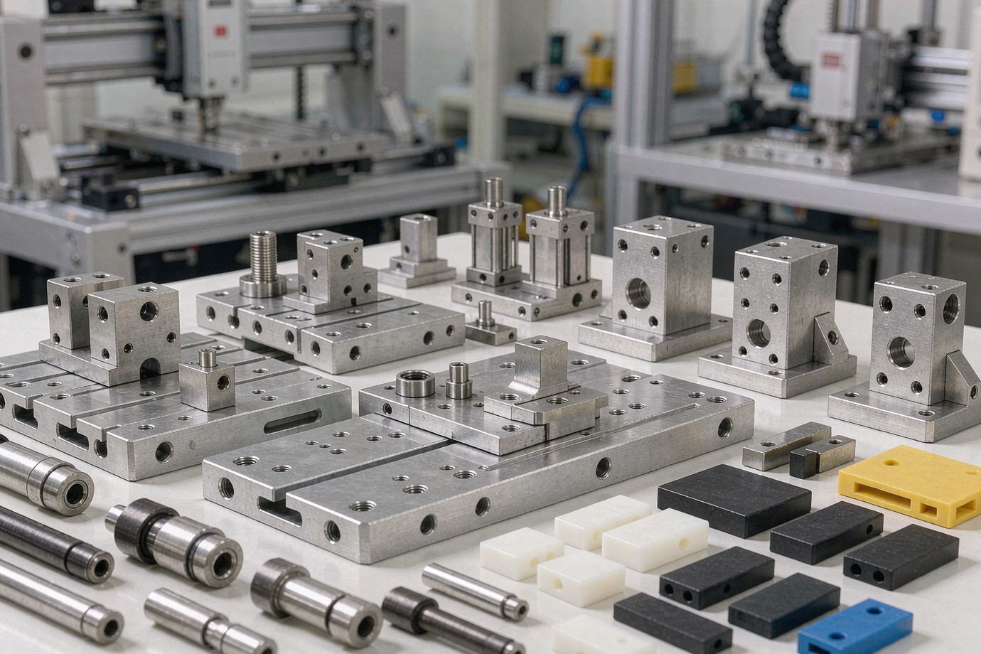
Xiamen Goldcattle manufactures custom industrial automation parts from drawings, 3D CAD models and approved samples. We make fixture plates, locating blocks, sensor and camera brackets, motor mounts, shafts, bushings, housings, sheet metal parts and molded or printed components for automated equipment. Six in-house processes are selected by part geometry, material, tolerance and volume. Each project starts with a review of the drawing, the mating interface and the inspection plan, with tight values applied only to functional features and batch consistency controlled against the approved revision.
Where Our Automation Scope Starts and Stops
This page covers mechanical components that go into automated equipment. It does not cover complete automation systems, controllers, sensors, drives, standard linear motion products or robot arms. If you need a standard stock part, a catalogue distributor is a better match; if you need a part made to your drawing, we are the right starting point.
For the wider set of machined parts, see CNC machining services.
Six Automation Part Families, Defined by the Job They Do
Buyers rarely search by material. They search for the part that has to work. These six families group components by the job they do in the machine, with the feature that usually decides whether the part assembles correctly.
- Fixtures & positioning partsFixture plates, locating blocks, locating pins, assembly and inspection fixtures, drill jigs and clamping blocks. The controlling feature is repeat location and the relationship between datum faces.
- Brackets & mounting partsSensor brackets, camera mounts, motor mounts, actuator mounts, connecting brackets, mounting plates and angle brackets. Hole position and mounting angle decide whether the part fits without forcing.
- Housings, covers & enclosuresMachine housings, motor and sensor housings, equipment covers, sheet metal enclosures and panels. The interface to internal parts and the cover joint matter more than the outside appearance.
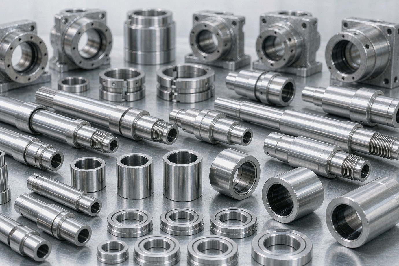
- Precision mechanical & motion partsShafts, shaft supports, bearing housings, bushings, spacers, coupling parts and interface blocks. Bore fit, concentricity and runout are the features that affect movement.
- Sheet metal & stamped partsBrackets, supports, connector plates, clips, retainers, panels and mounting plates. Bend angle, flange dimensions and hole location are checked against the flat pattern and the formed part.
- Engineering-plastic & printed partsWear blocks, guides, insulating parts, spacers, functional housings and prototype fixtures. Material behaviour under load and temperature decides the route as much as the shape.
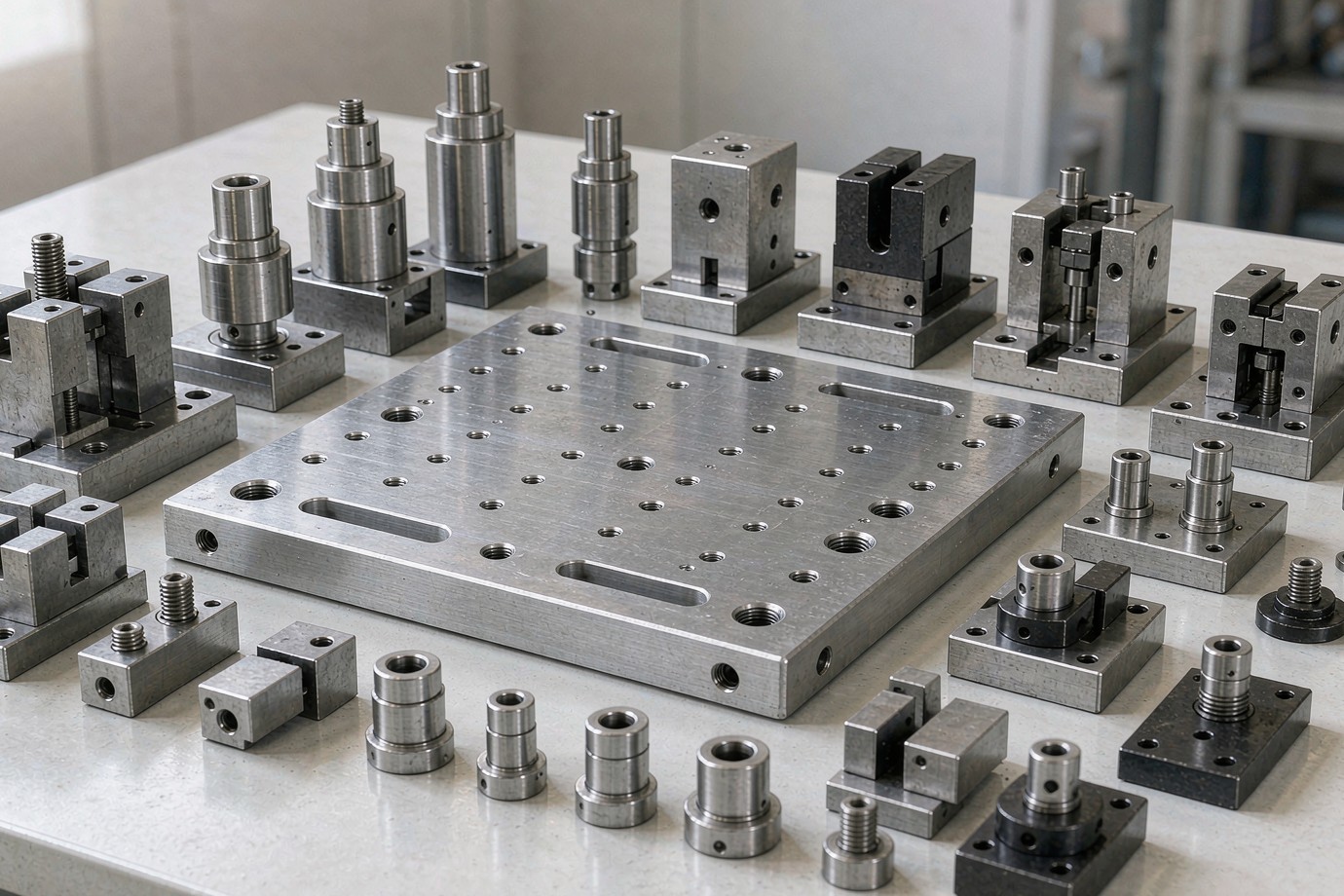
For dedicated detail on fixture design and locating principles, read custom CNC jigs and fixtures.
Which Automation Equipment These Parts Go Into
We describe applications by the parts actually made and the interface they have to meet. The equipment name is less useful than the drawing, the load and the mating component.
Fixtures and locating parts
Plates, blocks and pins that hold a workpiece in a repeat position through an assembly cycle.
Mounting and alignment
Camera brackets, sensor mounts and inspection fixtures where angle and position affect the measurement.
Mechanical interface parts
Brackets, mounting plates and connector parts made to the mechanical interface on the tool or fixture.
Structure, motion and covers
Shafts, supports, sheet metal structures and housings built to the machine builder's drawing.
Robot-side mechanical parts are covered in more detail on the robotic end effector parts page.
The Assembly Requirements Table: What Each Part Must Control
This is the section an engineer usually checks first. It connects a part type to the features that affect assembly and to the concern a buyer raises before ordering.
| Component type | Critical features | Typical buyer concern |
|---|---|---|
| Fixture plates | Flatness, hole position, datum relationships | Repeatable positioning across a shift |
| Locating blocks and pins | Pin position, fit, wear surface, hardness | Same location after a tooling change |
| Sensor and camera brackets | Hole position, perpendicularity, mounting angle | Sensor alignment without shimming |
| Motor mounts | Bore fit, mounting interfaces, flatness | Assembly compatibility with the gearbox or frame |
| Shaft supports and bearing housings | Bore diameter, coaxiality, perpendicularity | Smooth motion and even bearing load |
| Housings and covers | Mating faces, sealing grooves, thread quality | Assembly and protection of internal parts |
| Sheet metal brackets | Bend angle, flange dimensions, hole location | Stable mounting on a thin structure |
| Plastic wear parts | Material wear, dimensional stability, creep | Service life and easy replacement |
A feature listed here is a candidate for a controlled tolerance and a matching inspection method. It is not a claim that every dimension on the part is held to the same tight value.
Why Drop-In Fit Matters More Than a Lower Unit Price
In an automation project, a part that costs less but needs rework at the machine costs more by the time the line is running. A bracket slot that does not line up, a locating hole that is marginally out of position, or a cover that will not seat flat all consume build time and adjustment.
Parts arrive within a general tolerance but the mating features do not line up. The team reams a hole, shims a bracket or grinds a face during assembly.
The datum scheme, the mating interface, the functional features and the order of operations, agreed from the drawing before a price is settled.
Datums, Hole Position and Repeat Location
Most automation fit problems trace back to reference features. A drawing may follow ASME Y14.5 or ISO GPS conventions; the project names the standard. Naming a standard is not a certification claim.
| Feature | Why it matters in assembly | How we control it |
|---|---|---|
| Datum faces | Set the part's position in the machine | Agree the datum order, then plan setup and inspection around it |
| Mounting hole position | Decides whether the part fits without forcing | Machine in one setup where possible; check position against the datum |
| Flatness and parallelism | Affect contact and alignment of a mounted face | Check by surface and coordinate measurement on functional faces |
| Bore and shaft fit | Control movement and bearing life | Treat as a functional fit, not a general dimension |
| Repeat location | Keeps the assembly consistent after re-clamping | Use locating features and controlled tooling, with in-process checks |
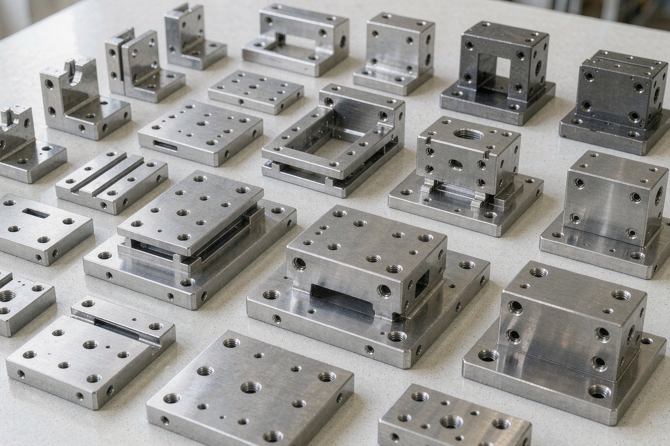
For the process behind tight functional features, see tight-tolerance CNC machining.
Choosing the Process by Part Geometry and Quantity
The same function can be made in several ways. The route follows material, shape, tolerance, working environment and volume - not a preference for one machine.
| Part situation | Route to evaluate | Procurement consideration |
|---|---|---|
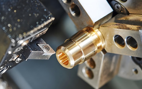
| Precise locating blocks, shafts, mounting plates | CNC machining | Tolerance, fit and inspection effort |
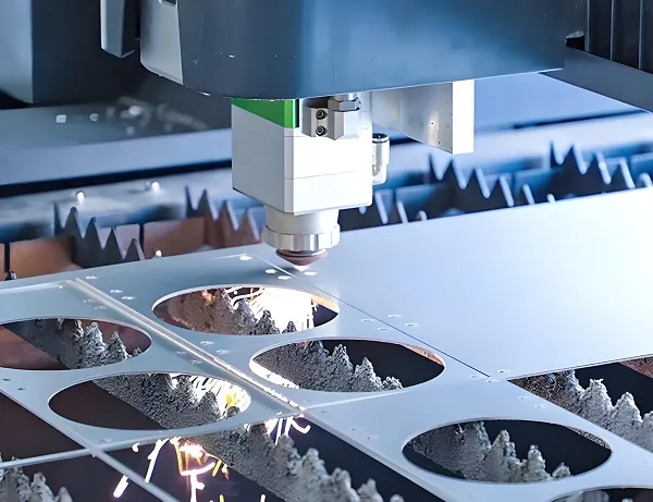
| Thin brackets, panels and covers | Sheet metal fabrication | Bend accuracy, hole position, finishing |
| Stable small metal parts at higher volume | Metal stamping | Tooling cost against unit cost |
| Complex metal housings at volume | Die casting with CNC finishing | Tooling investment and post-machining |
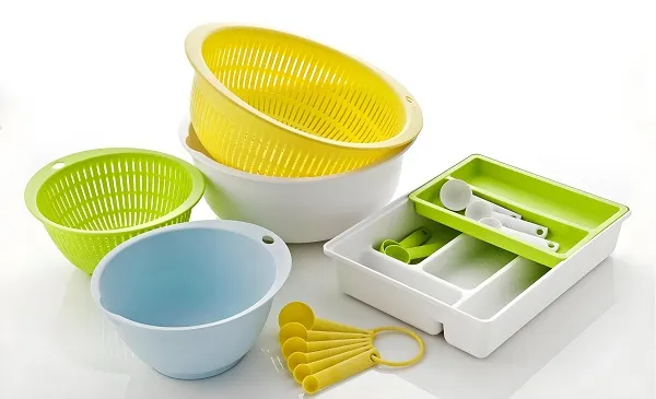
| Plastic housings and functional parts at volume | Injection molding | Resin, tooling and dimensional stability |
| Prototype fixtures and structural samples | 3D printing | Prototype speed and functional validation |
Related reading: CNC aluminum brackets, sheet metal fabrication and die casting services.
Materials for Motion, Wear and Working Environment
Material choice in automation is driven by the working condition as much as by strength. Tell us the environment and the required grade or condition, and we will confirm what is available rather than assign a grade from a list.
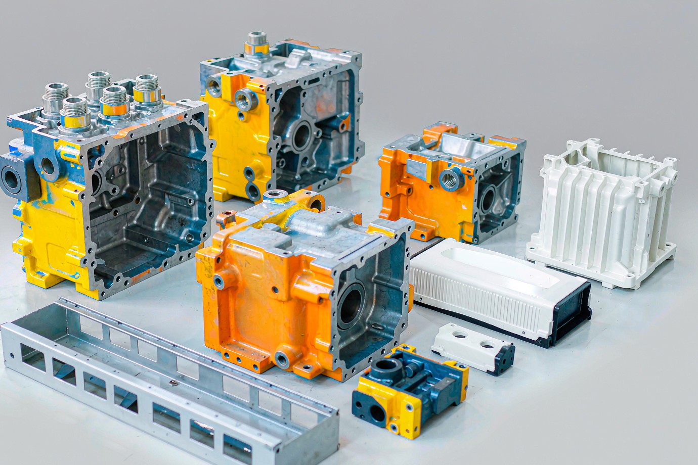
| Material group | Common grades | Points to confirm |
|---|---|---|
| Aluminum | 6061-T6, 7075-T6, 5052 | Strength, corrosion protection and anodizing effect on fits |
| Stainless steel | 303, 304, 316L | Medium, cleaning method and corrosion environment |
| Carbon and alloy steel | 1045, 4140 | Heat treatment, protection and dimensional change |
| Brass | C360 and other applicable grades | Grade and medium compatibility |
| Engineering plastics | POM, nylon, PEEK, PTFE | Moisture absorption, creep and temperature limit |
Finish and Fit: What Coatings Change at Assembly
Finishes are chosen for a function, then checked for their effect on dimensions. The operation name matters less than what happens to a fitted hole, a thread or a sealing face.
| Finish | Function | What to call out |
|---|---|---|
| Anodizing / hard anodizing | Aluminum surface and corrosion behaviour | Coating build-up on fitted holes and bores |
| Passivation | Stainless surface cleanliness | Standard and method defined by the project |
| Plating / electroless nickel | Steel corrosion and contact surfaces | Build-up on threads and close fits |
| Bead blasting / polishing | Appearance and roughness | Cosmetic reference by sample where needed |
| Heat treatment | Mechanical properties where specified | Distortion and finishing sequence |
Mark masking areas on the drawing and state whether critical dimensions are checked before or after finishing. If a face must stay bare for fit or contact, call it out explicitly rather than leaving it to the finisher.
Inspection Tied to the Assembly Requirement
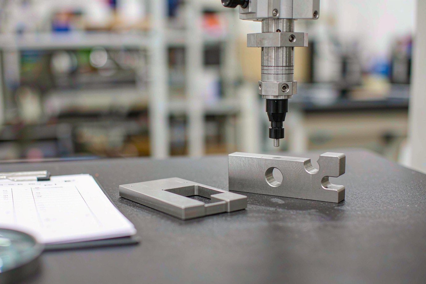
A useful report measures the features the drawing made critical, using a method that can see the stated tolerance. It is matched to the part, not applied as the same checklist to every order.
| Inspection item | What it answers | When it applies |
|---|---|---|
| Coordinate measurement | Critical dimensions, hole position and geometric relationships | Agreed functional features on the drawing |
| First-article inspection | Whether the first part matches the drawing and revision | New part or revised drawing |
| Material verification | Grade and batch information | Where traceability is required |
| Production batch checks | Whether repeat parts stay within the agreed limits | Repeat production runs |
One Supplier Across Part Families and Processes
An automation build often needs fixtures from one route, covers from another and plastic parts from a third. Coordinating them under one drawing review shortens the loop when an interface changes.
- Drawing review
- →
- Route by part
- →
- Agreed inspection
- →
- Repeat supply
All six core processes - CNC machining, injection molding, mold making, 3D printing, die casting and sheet metal fabrication - are performed in-house under one ISO 9001:2015 quality system. Founded in 1998, Goldcattle reviews each part against its own geometry and function, so a bracket, a housing and a locating block are routed and inspected on their own terms.
From Sample to Repeat Batch Without Rework
The risk in automation supply is not the first part. It is the fiftieth part in a later batch arriving with a slightly different interface. A controlled path keeps the approved definition stable.
- Engineering reviewDrawing, interface, route and inspection scope.
- PrototypeFirst parts from the agreed material and route.
- First-article checkCritical features against the approved revision.
- Drawing and sample approvalChanges confirmed before release.
- Repeat productionBatch checks against the agreed plan.
What to Send for an Automation Parts Quote
A review can only be as accurate as the information supplied. Send what you have; if a requirement is missing, we will ask rather than assume.
- 3D CADSTEP or IGES model of the part.
- 2D drawingPDF or DWG with dimensions, datums and GD&T.
- MaterialGrade and condition, or the requirement if you need a recommendation.
- QuantityOrder quantity; annual demand is helpful but optional.
- Critical featuresFits and tolerances that must be controlled.
- Surface finishFinish, masking areas and the acceptance point.
- InspectionFirst article, dimensional report or material documents.
- FunctionWhat the part does and what it mates with in the assembly.
- Target dateRequired delivery and any phased schedule.
Questions Automation Buyers Ask Before Ordering
What are industrial automation parts?
Which automation parts can be custom manufactured?
Can you make automation parts from drawings and 3D CAD?
How do you keep hole positions and datums consistent across batches?
Which process is best for automation brackets?
Can you supply both prototypes and repeat production?
What materials are available for automation parts?
How are automation parts inspected?
Do you provide first article inspection and material certificates?
What should I include in an automation parts RFQ?
Can one supplier make metal, sheet metal and plastic automation parts?
Do individual automation parts need product certification?
Send the Drawing and the Assembly It Fits
Share your 2D drawing and 3D CAD with the material, quantity and critical features. We review the interface, the route and the inspection scope before quoting, and tell you where a tolerance is worth paying for.
Send Your Automation Parts Drawing →Drawing-based custom manufacturing. Tolerances, finish and inspection are agreed per order. Founded in 1998.