Custom CNC Machined Equipment Covers and Cover Plates
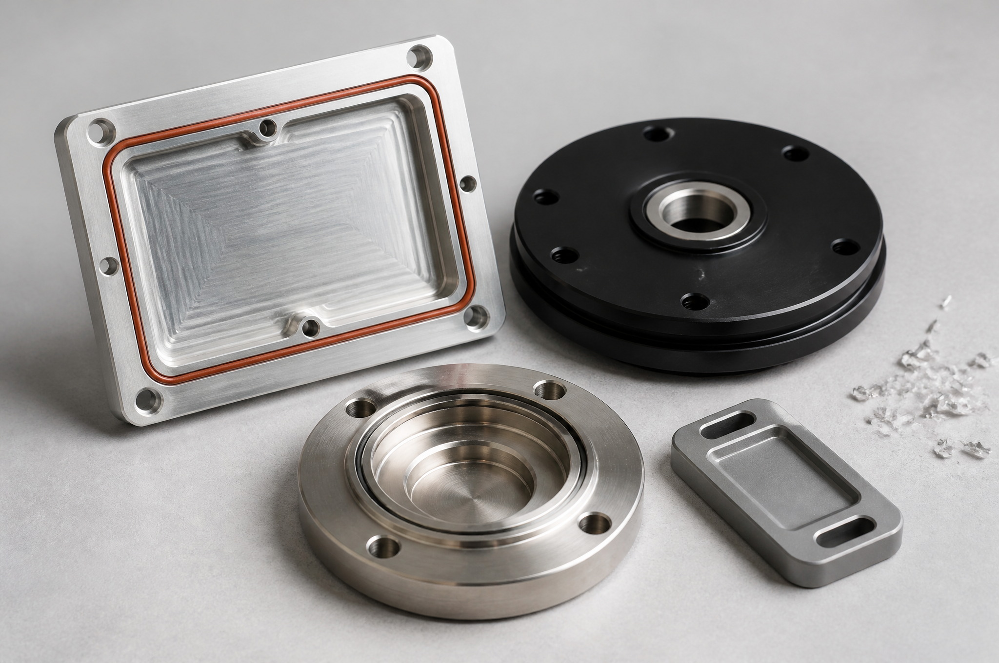
A cover is not a plate with holes in it. It is the joint that closes a boundary — oil, coolant, dust, water, air, or an electrical enclosure — and it is judged at that joint, not at its outline. Three features decide whether it works: the mating face that has to sit flat, the register that centers it on the housing, and the groove that holds the seal. All three live on the same side of the part, and all three have to be machined from one datum or they fight each other.
At a Glance
A machined cover works or fails at three fitted features, and they are all machined from one datum in one setup: the face that seats on the housing, the register that centers the cover on it, and the groove that carries the seal. If those come from three different setups, three small errors add up in the same direction and the cover sits cocked — the gap opens on one side, the O-ring is compressed hard on the other, and it leaks at the point where nobody measured. This is why the page spends more words on the mating side than on the outline, and why a drawing that gives overall size and hole positions but leaves out flatness, register diameter or groove depth is not yet a cover drawing.
Where This Page Fits
The site has several pages that touch covers from different directions. None of them treat the cover as a sealing joint, which is what this page does; everything else is handed back.
| Page | What it answers | What this page does about it |
|---|---|---|
| This guide | How machined covers are specified, machined, finished and proved, and what the buyer has to define | — |
| Bulldozer cover | Heavy equipment covers for earthmoving and mining: impact, abrasion, field replacement | No heavy-equipment section here; that page owns the application |
| Custom CNC parts | General machined components, materials and machining capability | No general capability list here |
| Sheet metal fabrication | Large thin-wall covers, guards, folded and welded enclosures | One comparison row in the routes chapter, nothing more |
| Enclosure injection molding | Plastic housings and plastic covers | Not covered here; a machined metal cover is a different purchase |
| Robotic end effector parts | Robot tooling: adapter plates, fingers, vacuum blocks | Different joint, different standard; see that page |
| Tight-tolerance machining | Achievable values by feature and material, and metrology | Which features to call out, not what the limits are |
| Die casting | Casting capability and tooling | One row in the routes comparison, for cast-then-machine covers |
A Cover Is a Joint Before It Is a Part
Every cover closes one of five boundaries. Which boundary it closes decides which machined feature is critical, and that decision should be visible on the drawing rather than left to the supplier.
| Boundary it closes | What the cover has to hold back | The feature that decides it | What is usually underspecified |
|---|---|---|---|
| Fluid under pressure | Oil or hydraulic fluid at working pressure | Sealing land flatness and finish, plus groove depth and bolt spacing | Bolt spacing relative to pressure: too far apart and the cover bows between screws |
| Oil or coolant splash | Splash, mist and drainage from a gearbox or machine tool | Gasket land and a drain path back to the sump | Where the fluid goes once it is inside the joint |
| Dust and water ingress | Airborne dust, washdown water, outdoor rain | Register fit, gasket compression, and the number of fasteners | Compression percentage: a groove that is too deep lets the gasket relax |
| Air or vacuum | Pressure difference across the cover | Face flatness and fastener preload; the cover is a diaphragm | Cover stiffness: a thin plate deflects between screws and lifts the seal |
| Electrical or EMI boundary | Dust, fingers, and conducted or radiated interference | Conductive contact faces, grounding bosses, and masked finish areas | That anodizing insulates, so a masked contact strip is needed for bonding |
Six Cover Families, Six Different Critical Features
These are not marketing categories. Each family fails in a different place, so each one has a different feature to control and a different inspection.
| Family | Where it is used | The feature that decides whether it works | Usual material |
|---|---|---|---|
| Cover plate | Closing an opening in a machine frame, a housing face or a gearbox side | Sealing land flatness and bolt-hole position; the plate's own stiffness between bolts | 6061-T6, 304, cast iron or aluminum |
| Motor end cover | Closing the drive or non-drive end of a motor or gearmotor | Bearing bore size and its relationship to the spigot that centers the cover on the frame | Aluminum for small frames, cast iron for large |
| Pump cover | Closing a pump casing, a valve body or a hydraulic manifold | Sealing land plus groove geometry, and bolt pattern relative to the pressure boundary | 316L, cast iron, bronze |
| Gearbox cover | End covers, bearing retainers and inspection plates on a gearbox | Bore position, seal groove, and a drain or fill port that lines up | Cast iron, aluminum, steel |
| Housing lid | Top or side lid of a machined or cast equipment housing | Mating face flatness and the register that keeps the lid from sliding | 6061-T6, 7075-T6, 304 |
| Inspection and access cover | Service openings that are opened and closed repeatedly | Repeatable location after refitting, plus a groove or gasket that survives being opened | Aluminum, stainless, steel |
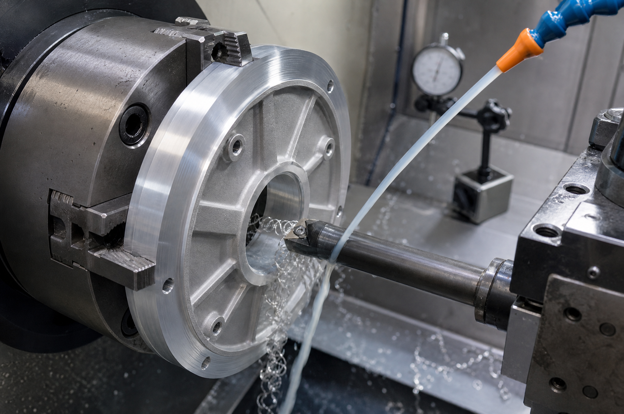
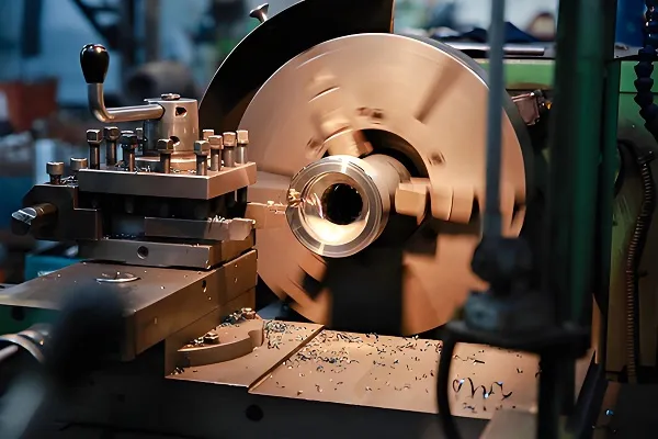
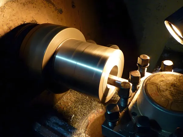
Two consequences follow from the table. The end cover and the pump cover are turned parts — bore, spigot, face and often the groove fall on one axis, so a lathe holds them in one chucking and the relationships survive. The cover plate and the housing lid are milled parts, where the problem is flatness across a face and hole positions in that face. Treating a turned cover as a milled one, or the reverse, is how a good part ends up with a bore that is not concentric to the spigot.
The Mating Side: Four Features, One Setup
Turn a cover over and the working side has four features, all of which refer to each other. Machining them in one setup is not a convenience; it is the only way the relationships hold.
| Feature | What it does | What goes wrong when it is loose | How to specify it |
|---|---|---|---|
| Mating face | Seats on the housing and carries the seal | The cover rocks, is pulled flat by the screws, and the seal gap opens on the opposite side | Flatness over the sealing land, measured free, and a surface finish if a gasket or O-ring needs one |
| Spigot register | Centers the cover on the housing bore or boss | The cover sits off-center; on an end cover the shaft is then off-center in the bore | A diameter with a fit and the face it is perpendicular to |
| Seal groove | Holds the O-ring or gasket at the compression it was designed for | Deep groove: the seal relaxes and weeps. Shallow groove: the seal is crushed and takes a set | Width and depth with tolerances, the seal section it is designed for, and the finish inside the groove |
| Bolt pattern | Clamps the joint and spreads the preload | The cover bows between widely spaced screws, lifting the seal in the middle of the span | Position and pitch, with a datum on the mating side — not from the outline |
The register is the feature buyers forget. A cover with a good gasket and a flat face will still leak if it is allowed to sit 0.2 mm off center, because the seal is then compressed unevenly all the way round. On a turned cover the register and the bore are cut in one chucking; on a milled cover the register and the bolt pattern are cut in the same operation as the face they sit on. Where a drawing puts them in separate views with separate datums, that relationship is lost before the first chip is cut.
Why a Flat Cover Still Leaks
Flatness is necessary and it is not sufficient. What seals a joint is compression of a seal at the right value, all the way round, staying there under pressure and temperature. A cover only supplies one of the inputs to that.
| Input to the seal | Who decides it | What a machined cover can and cannot do |
|---|---|---|
| Groove depth and width | Tool design, cut on the cover | Can hold it to the drawing and report the measured values |
| Seal section and material | The seal supplier and the design engineer | Cannot choose it; a groove cut for one section is wrong for another |
| Face flatness and finish | Machining and inspection | Can hold it, and can report it in the free unclamped state |
| Bolt spacing and preload | Housing design and assembly | Can hold hole positions; cannot control how the joint is tightened |
| Cover stiffness | Thickness and rib design | Can machine it as designed; cannot add stiffness that is not in the drawing |
| Pressure, temperature, fluid | The application | Cannot be inferred from a part that measures correctly |
This is why a supplier who says "our covers are IP67" is describing something they cannot test. An IP or UL rating belongs to an assembled enclosure, tested under a stated method, not to a machined part. What can be stated is narrower and more useful: the groove dimensions that were cut, the flatness measured free, the register fit, and — where the customer sends the mating housing — whether the pair actually seats.
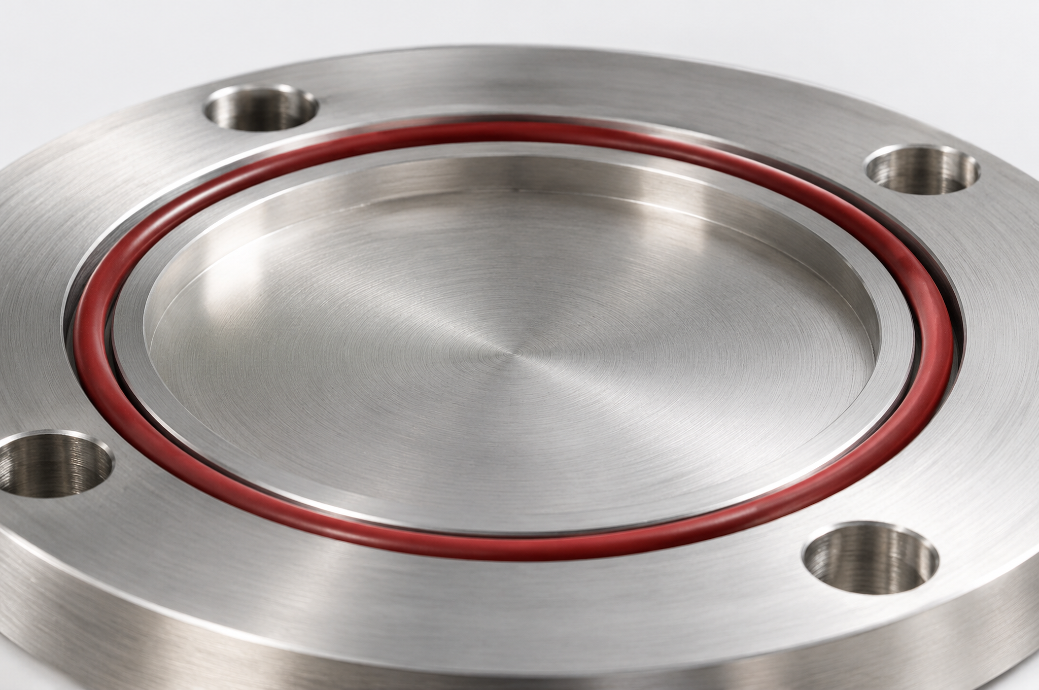
Groove Geometry: The Smallest Feature With the Most Effect
| Groove dimension | Why it matters | What the drawing should say |
|---|---|---|
| Depth | With the seal section, it sets the compression: too deep and the seal does not touch, too shallow and it is over-compressed and takes a set | Depth with tolerance, and the nominal seal section it was designed around |
| Width | Room for the seal material to displace when compressed; too narrow and the seal binds and wears | Width with tolerance, and the corner radii at the bottom |
| Floor finish | A rough floor creates a leak path under the seal, and a polished one can be as bad if it is wavy | Finish for the groove floor and walls, stated separately from the face |
| Position | Sets the seal line relative to the bolt circle and the register; wrong position compresses the seal off-center | Position from the register or the bore, not from the outside diameter |
| Continuity | A groove interrupted by a bolt hole or a slot is a leak path, unless it is designed to be | State whether the groove runs continuous, or where it is allowed to break |
The most common groove mistake is not a tolerance problem. It is a groove designed for one seal section and cut to a drawing that names a different one, or a groove whose depth was quoted for a static face gasket and then used with an O-ring. Both look correct on the bench and both leak in service. Where the seal is not yet chosen, say so — a groove can be quoted against a stated section, and cut once that section is confirmed.
Thin Walls, Distortion and the Order of Operations
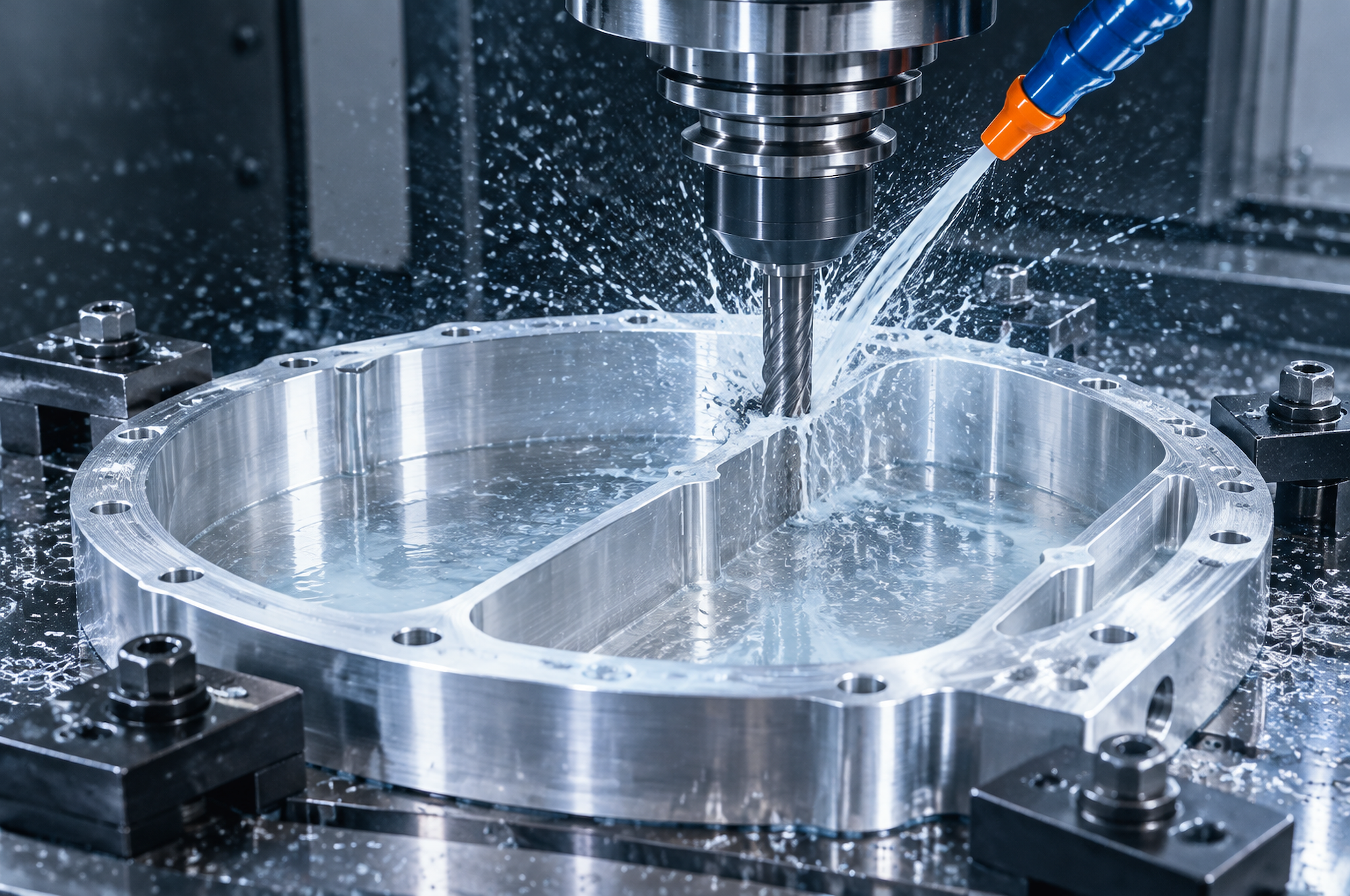
A cover is usually the thinnest part in the assembly, and it is expected to stay flat. Those two facts are in tension: removing metal releases stress, and clamping to remove metal adds stress. The sequence is what keeps the finished face from carrying both.
| Step | What happens | What it prevents |
|---|---|---|
| 1. Face the datum side | One face is made flat and true and becomes the reference for everything else | A part built from a wavy first face, which no later step can recover |
| 2. Rough the pockets | Most of the material is removed, leaving stock for finishing | Cutting to size and then discovering the part has moved |
| 3. Stress relief where it is needed | Between roughing and finishing, for parts where removal is heavy relative to wall thickness | Distortion that appears after the last cut, when nothing can be corrected |
| 4. Semi-finish and re-fixture | The part is re-seated on the machined datum, not on the raw edge | Clamp-induced error carried into the final cut |
| 5. Finish the sealing face | The face that meets the housing gets its final cut with the part relaxed | A flat face that springs when the clamps come off |
| 6. Cut register, groove and holes | All relative to the finished face, in the same setup | Relationships lost between operations |
| 7. Inspect unclamped | Flatness and groove depth measured free, on supports, not in the vice | Reporting a number that only exists while the part is clamped |
Two design notes that come out of this. Ribs are usually better than a thicker wall: a rib adds stiffness where the bending is, without adding mass across the whole face, and it does not need a deep pocket on the opposite side. And a thin wall is a machining conversation, not a single minimum number — what can be held depends on the material, the depth-to-thickness ratio, the cutter reach and how the part is supported, so it is confirmed per part rather than published as a rule for all covers.
Materials: What Each One Does to the Cover
Material choice on a cover is driven by three things in this order: what the boundary contains, how stiff the cover has to be, and what happens to the surface afterwards. Strength is rarely the deciding factor on a part this shape.
| Material | Where it earns its place | Where it bites |
|---|---|---|
| 6061-T6 aluminum | The default for machined covers: stable, machines cleanly, anodizes evenly, carries a good sealing face | Not a stiff material, so a large unsupported span needs ribs rather than thickness; threads need enough engagement |
| 7075-T6 aluminum | Covers that must be light and stiff at the same time, or that see higher loads | Less corrosion resistant, so it wants anodizing; less forgiving of sharp internal corners; costs more |
| 304 stainless | Covers exposed to washdown, cleaning agents or general damp industrial air | Work hardens and galls; deep pockets take far longer than in aluminum; threads and fits need care |
| 316L stainless | Chloride exposure: coastal, marine, chemical process, de-icing salt | Cost and machinability. It is not automatically right for every corrosion question, and passivation matters as much as the grade |
| Carbon and alloy steel | Structural covers, large covers where stiffness per cost matters, and covers that will be coated | Every cut edge and thread is a corrosion site unless the coating covers it; the finish becomes part of the design |
| Cast blanks (aluminum or iron) | Shapes with ribs and bosses that would waste most of a billet, in repeat quantities | Porosity and dimensional variation in the blank; the machined features are only as reliable as the cast datum |
On aluminum and heat: a machined aluminum cover does conduct heat, and it is often chosen partly for that. But heat transfer depends on the heat path, the contact area, the airflow and the surface, not only on the material. A cover that measures correctly and is made of 6061 is not thereby a thermal solution, and no dimension on a drawing proves it.
Four Ways to Make a Cover, and When Each One Wins
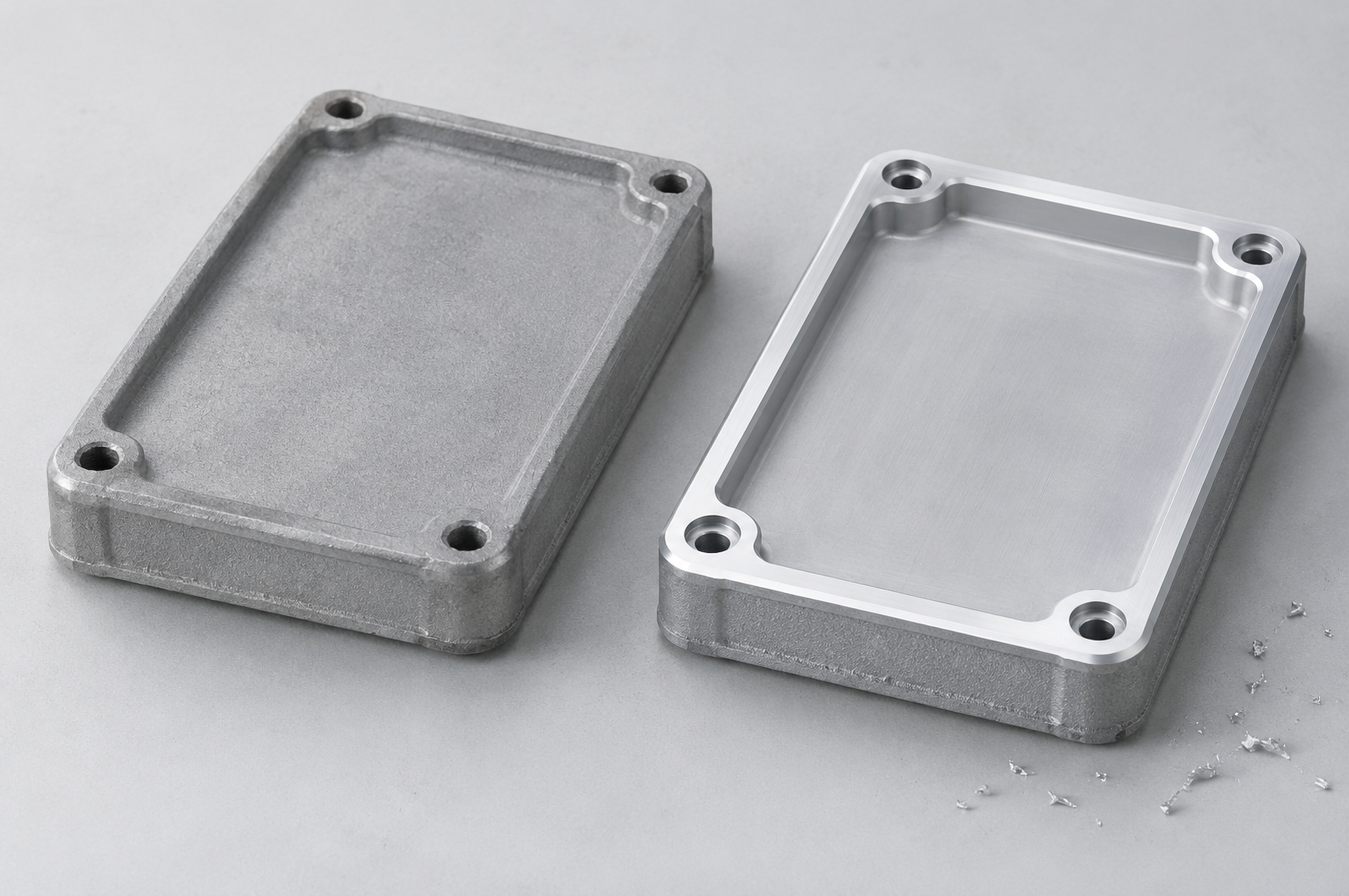
Covers are not all turned from solid. The right route depends on the shape of the part, the quantity, and whether the tooling investment can be carried. Quoting every cover the same way is how a buyer ends up paying billet prices for a shape that should have been cast, or tooling costs for two hundred pieces.
| Route | Right for | What you gain | What it costs |
|---|---|---|---|
| Machined from solid billet | Small and medium covers with complex internal geometry, prototypes, and quantities that cannot carry tooling | No tooling, free geometry changes between builds, and machined pockets, ribs and boss positions as designed | High material removal: a deep cover can start from a block several times its finished weight |
| Plate plus CNC | Flat cover plates, inspection and access covers, gasket-landed plates | The most economical machined option; the plate comes flat and only the features are cut | Not for deep three-dimensional inner geometry; a thick plate is still all material |
| Casting plus CNC finishing | Ribbed covers, end covers and housings in repeat quantities where the cast shape is close to the finished one | Low material waste per part, ribs and bosses formed rather than cut, better cost per piece at volume | Tooling and casting validation, porosity risk, and machining allowance that has to be designed in |
| Sheet metal plus local machining | Large thin covers and guards where the main structure is folded and welded | Efficient for large panels and enclosures; the folded form supplies stiffness cheaply | Dimensional control after folding and welding, and machined features only where they are added locally |
Tolerances: What to Call Out on a Cover
A cover drawing that carries one general tolerance and nothing else is under-specified in exactly the place that matters. The right approach is the opposite of a blanket number: mark the few features that decide the joint, and let the rest run on general tolerance.
| Callout | What it controls | Where it belongs on a cover |
|---|---|---|
| Flatness | Whether the sealing land can seat without being pulled flat by the screws | On the mating face, measured free, over the seal land |
| Perpendicularity | Whether the register stands square to the face it locates against | Register diameter to the mating face |
| Position | Whether the bolt pattern and the groove sit where the housing expects them | Holes and groove to the register or the bore, with a stated datum |
| Coaxiality or runout | Whether a bearing bore is concentric to the spigot that centers the cover | Bore to register, on end covers and bearing retainers |
| Size with a fit | Whether an O-ring boss or a spigot actually interferes or clears correctly | Register and bore with a fit designation, not a bare number |
| Groove dimensions | Compression of the seal | Width and depth, with the seal section named |
| Surface texture | Whether a gasket can seal on the land, and whether an O-ring slides or grips | On the sealing land and inside the groove, separately |
Why not one tight number everywhere. A blanket tight tolerance on a cover forces slower passes, extra setups, more inspection and often a stress-relief step, and it still does not tell anyone which feature decides the joint. It also creates a false impression on large covers: on a part several hundred millimeters across, the number that matters is the flatness of the seal land and the position of the holes, not the size of the outline. Which values can actually be held is a per-feature question — it depends on the material, the size, the geometry and how the feature will be measured, so it is agreed on the drawing rather than published as a page-wide figure.
Finish, and What It Does to the Interface
On a cover, a finish is not decoration at the end of the process. It is a dimension added to a fitted surface, and on some parts it is an electrical property as well.
| Treatment | What it does for a cover | What it changes | What to specify |
|---|---|---|---|
| Clear anodizing | Wear and corrosion protection with the machined look kept | Grows a film on every surface: bores tighten, spigots grow, grooves get shallower | Which features are masked, and whether the fitted dimensions are inspected before or after |
| Hard anodizing | Higher wear resistance on a cover that is opened often or slides | Adds more than clear anodizing, and reduces fatigue strength at sharp corners | Edge radii, masked areas, and the fit allowance for the thicker film |
| Passivation | Removes free iron from stainless after machining, so the passive layer re-forms | No measurable change to size; it is a chemical clean, not a coating | That it is required, and after which operations |
| Powder coating | Color and a barrier layer, mainly on steel covers | Adds film thickness on all faces: holes tighten, threads need masking, the sealing land may need protection | Masked threads, bores and seal lands, and touch-up for cut edges |
| Bead blasting | Even matte finish, hides tool marks | Rounds edges slightly and changes the roughness of a face | Whether a sealing land may be blasted at all |
| Electroless nickel | Hard, uniform, corrosion-resistant surface on steel or aluminum | Adds a uniform film, including inside bores and threads | Allowance on fitted features and thread gauging after plating |
Inspection: Part, Pair, System
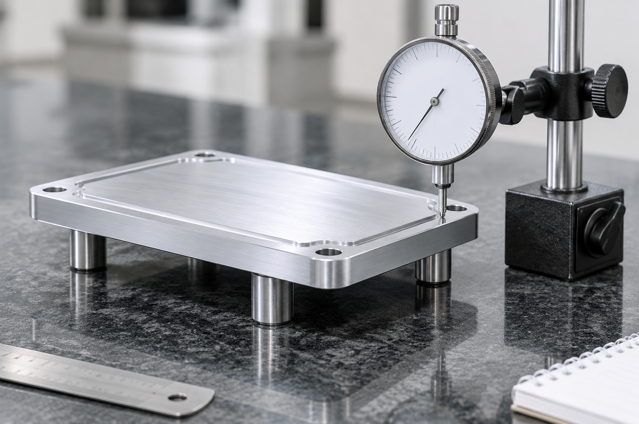
There are three levels of proof on a cover, and they answer different questions. Confusing them is how a supplier ends up promising something no inspection can show.
| Level | What is checked | What it proves | What it does not prove |
|---|---|---|---|
| 1. The part | Overall size, face flatness free, register diameter, groove width and depth, bore size, bolt positions, threads | That the features are where the drawing says, in a stated measurement condition | Whether it will seat on a real housing, or whether the joint will seal |
| 2. The pair | Fit against the mating housing or a check fixture: does it seat, does the register enter, do the holes line up, is the gap even round the seal line | That this cover fits that housing — the question most buyers actually care about | Anything about pressure, temperature or long-term relaxation |
| 3. The system | Leak or pressure testing of the assembled unit, by the customer or an agreed test house | Whether the assembled joint holds under the stated conditions | Nothing about the part alone; this is a design and assembly result |
Where a project needs level 2, the mating housing or a check fixture has to be available — that is the only way to check a joint. Where it needs level 3, the test is specified, witnessed and reported on the assembly, and it belongs to whoever builds the unit. A dimensional report on a cover is level 1 and nothing more; it is honest evidence, and it should not be dressed up as a sealing guarantee.
Documents That Come With a Cover Order
- Material certificate — grade and heat or lot, so a repeat order can be compared with the first.
- Dimensional inspection report — the characteristics marked on the drawing, with values, the instrument used, and whether each was measured clamped or free.
- First article inspection report — every characteristic on the drawing measured once before the run is released, which becomes the acceptance basis for repeats.
- Groove and flatness record — the two numbers that decide the seal, reported separately rather than buried in a table of general dimensions.
- Fit check record, where a mating part was supplied — what was assembled, and what the result was.
- Surface treatment record — what was applied, to which parts, in which batch, and what was masked.
- Batch traceability — which stock or casting a carton came from.
From Prototype to Repeat Production
Cover programs move in a predictable way: a prototype to prove the fit, a revision or two while the housing is being finished, then a repeat order when the machine goes into series. The process below is built so that the repeat is made to the same basis as the approved first article.
| Step | What happens | What you get back |
|---|---|---|
| 1. Drawing and model review | Geometry, datums, mating features, seal groove and boundary conditions are read together; unclear notes are listed | A question list, manufacturability notes, and the assumptions the quote is based on |
| 2. Route selection | Billet, plate, casting or sheet, chosen against shape and quantity | A stated route, and the features that carry the risk on that route |
| 3. Prototype machining | One or a few parts, to prove the fit on the real housing | Parts, and the inspection result agreed at quoting |
| 4. First article inspection | The drawing as finally approved is measured in full, with the flatness and groove record | An FAI record that becomes the acceptance basis for repeats |
| 5. Revision and adjustment | Changes found during assembly are folded in; the drawing revision is frozen | A confirmed revision, quoted and recorded as the new basis |
| 6. Repeat production | Runs to the frozen drawing, with material, finish and inspection records per batch | Parts with the same acceptance basis as the approved first article |
Legacy Machines: Replacement Covers Without a Drawing
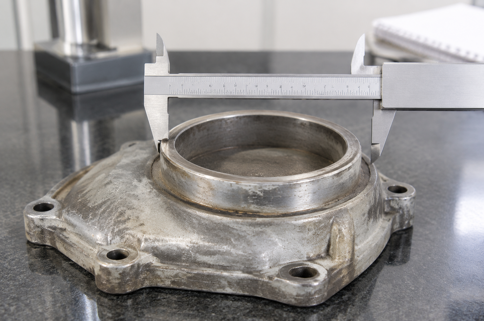
A large share of cover enquiries come from machines that are still running with no spare parts: the OEM has stopped supporting them, and the only drawing is the part itself. That is workable, but it has to be done in a strict order, because a worn part is evidence rather than a specification.
- Identify the functional datums first. The register that centers the cover, the face that seats it, and the bolt pattern that clamps it. These are reconstructed before anything else, because everything on a replacement is measured from them.
- Treat worn surfaces as worn. A bore that has run for years is oversize, a bolt hole that has been loose is oval, and a sealing face that has been compressed carries a mark. Copying those numbers reproduces the wear.
- Use the mating part as a cross-check. The housing, the shaft or the gasket tells you what the original part must have been; where it is available, measure against it rather than against the worn cover alone.
- Send the reconstructed dimension table for approval before cutting. A table of values with the worn ones marked as reconstructed is far cheaper to argue about than a finished part.
- Mark the reconstructed values in the report. A replacement part whose dimensions were inferred should say so, so that the next replacement is not built on an assumption that has quietly become a specification.
- Keep the confirmed drawing. The second replacement should be a repeat order from a filed drawing, not a second reverse-engineering exercise.
Where the original material is unknown, the grade is chosen against the environment rather than guessed from appearance: a cast cover that ran dry for twenty years may not need the same grade as one that ran in washdown. Changing the grade is a decision the customer should make with the reason stated, and it is recorded with the drawing.
What to Send for a Cover Quote
A cover enquiry stalls for one reason: the drawing shows a part, not the joint it has to close. These items turn a shape into a quotation that can be compared with another supplier's.
| Item | What to include | What goes wrong without it |
|---|---|---|
| 3D model and 2D drawing | STEP or IGES, plus a drawing with tolerances, datums and notes, at the current revision | The geometry is interpreted and the critical features are guessed |
| Mating housing drawing | The part the cover bolts to, or at least the interface dimensions | The joint cannot be checked, and the fit is discovered at assembly |
| What it must keep out | Oil, coolant, dust, water, air or vacuum, at what pressure and temperature | The groove and flatness are quoted to no target, and the seal is chosen by habit |
| Seal details | O-ring or gasket section if known, and whether the groove is designed around it | A groove is cut for the wrong section and leaks at the first test |
| Material and stock type | Grade, and whether the part will be cut from billet, plate, casting or sheet | The route is assumed, and the price is right for a different one |
| Wall thickness and internal features | Pockets, ribs, bosses and any minimum wall | Thin-wall distortion is discovered after the first part |
| Mounting and fastening | Hole pattern, thread standard and depth, counterbores, dowels, tool clearance | Threads arrive in the wrong standard, or with no room for the driver |
| Finish | Anodizing, passivation, powder coating, plating, and which areas must be masked | The finish is added later and closes a bore or insulates a grounding face |
| Quantity | Prototype, pilot and annual volume | The tooling decision is made on the wrong number |
| Inspection | Critical characteristics, reports required, and whether a fit check against the housing is wanted | The evidence arrives without the number that mattered |
| Packaging | Protection for a finished, possibly coated sealing face | A sealed face arrives marked, and the mark is a leak path |
Frequently Asked Questions
What are CNC machined equipment covers?
Which types of covers can you machine?
Can you manufacture covers with O-ring grooves?
How do you control the flatness of a cover plate?
What tolerances can you achieve on a machined cover?
Can you machine large covers and cover plates?
How do you stop thin-wall covers from distorting?
Should I choose billet machining, casting, or sheet metal for a cover?
Can machined covers meet IP67 or similar sealing ratings?
Can you check that a cover fits my housing?
Can you make replacement covers for obsolete equipment?
What information is needed for a cover quote?
Send the Drawing and the Housing It Closes
A 3D model or 2D drawing, the mating housing interface, what the cover has to keep out and at what pressure, the seal section if it is known, the material and quantity, and the finish. The review comes back with the route, the features that carry the risk, what will be measured free, and what can only be proved on the assembled unit.
Request a Cover QuoteSTEP · IGES · DWG · DXF · PDF · NDA on request
Where to Read Next
CNC machining services
Machines, envelopes, materials and lead times. Services
Bulldozer and heavy equipment covers
Heavy covers for earthmoving, mining and field replacement. Heavy covers
Tight-tolerance machining
Achievable values by feature and material, and metrology. Tolerance
Die casting
Cast blanks and tooling, for covers that repeat. Casting
Sheet metal fabrication
Large folded and welded covers, guards and enclosures. Sheet metal
Surface finishing
Anodizing, passivation, coating and what they change. Finishing
Stainless machining
Grades, corrosion behavior and cutting practice. Stainless
Material library
Grades, properties and stock availability. Materials
Quality and certifications
The quality system and the documents issued per project. Quality