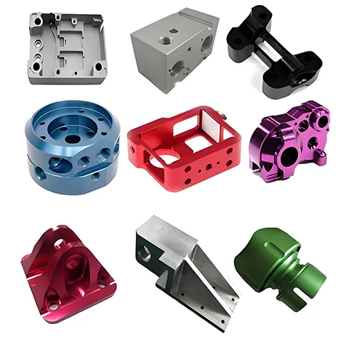


Custom CNC Machined Parts | Feature Relationships
Place of Origin : XiaMen, China
Brand : JSD
Model : CNC-44
Model : CNC customized parts
Material : Stainless steel, steel, aluminum, brass, titanium, steel special treatment sandblasting, anodizing, plating, polishing, etc.
Quality control : 100% inspection before shipment
Certificate : ISO9001
Key words : CNC machining parts CNC machining service
Name : CNC customized machining
Description
Custom CNC Machined Metal & Plastic Parts
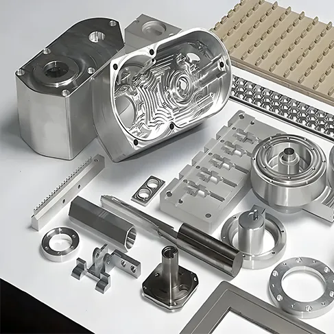
A machined part is not accepted because its dimensions are inside tolerance. It is accepted because the features that mate with something else are right relative to each other — the two holes that take a pin, the bore that has to be square to the face it seats on, the wall that must not move when the last clamp comes off. That set of relationships is what a drawing actually specifies, and it is what we machine to. This page is about the parts, the features and the evidence; the machines and the plant are on the services page.
- Milled · turned · 5-axis
- Aluminum · stainless · titanium · brass
- PEEK · POM · PEI · PTFE · PA
- CMM report · FAI · material certs
What This Page Answers, and What It Hands Back
This page covers the part
Part families and what distinguishes them; which machining route a geometry actually needs; material grades and what each one does badly; the features that decide whether a part is holdable; how tolerance is stated per feature rather than per shop; what a design review changes; finish by substrate; the documents that come with an order; and how the same part behaves at one piece and at ten thousand.
It is written for the person who has to release a drawing and defend it afterwards: a design engineer, a manufacturing engineer or a sourcing engineer at an OEM that has the drawing and needs the part.
This page does not repeat the plant
Spindle hours, floor area, machine list, company history and process photography live on the CNC machining services page, because that is the page a buyer reads when they are qualifying a supplier rather than releasing a part. Repeating it here would make two pages compete for the same query and neither one better.
What this page keeps for itself is the engineering conversation that happens after the supplier is qualified and before the first chip is cut.
| Question you actually have | Where it is answered |
|---|---|
| Does my geometry belong to a milled, turned or multi-axis family? | Below, on this page |
| Which material grade suits the load, the environment and the budget? | Below, plus the material library for full grade data |
| Which feature on my drawing is the one that will decide the price? | Below: the feature budget |
| How is tolerance stated, and what does ±0.005 mm apply to? | Below, plus the tolerance tables on the services page |
| What plant, equipment and capacity will make it? | CNC machining services |
| How is the part actually cut, step by step? | CNC milling and CNC turning |
Four Part Families, Distinguished by Geometry Rather Than by Material
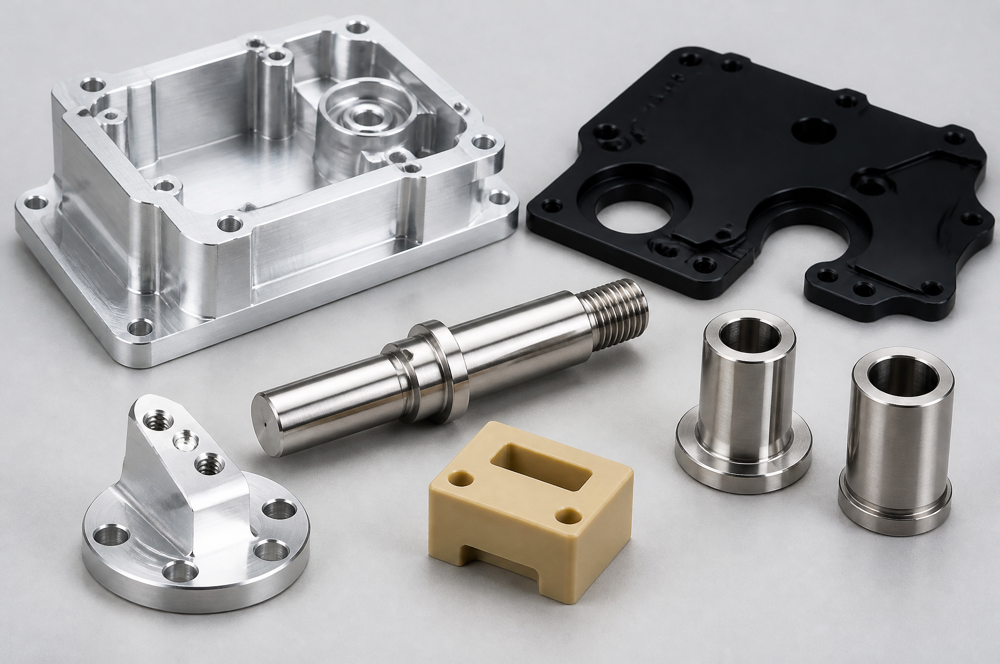
Part catalogues usually sort by material, which is the wrong axis for a buyer. Two aluminum parts can need completely different shops: a plate with a pocket on one face is a milling job, while a 300 mm shaft with three diameters, a thread and a cross hole is a turning job with a milling operation inside it. Sorting by geometry tells you what will actually be hard about your part.
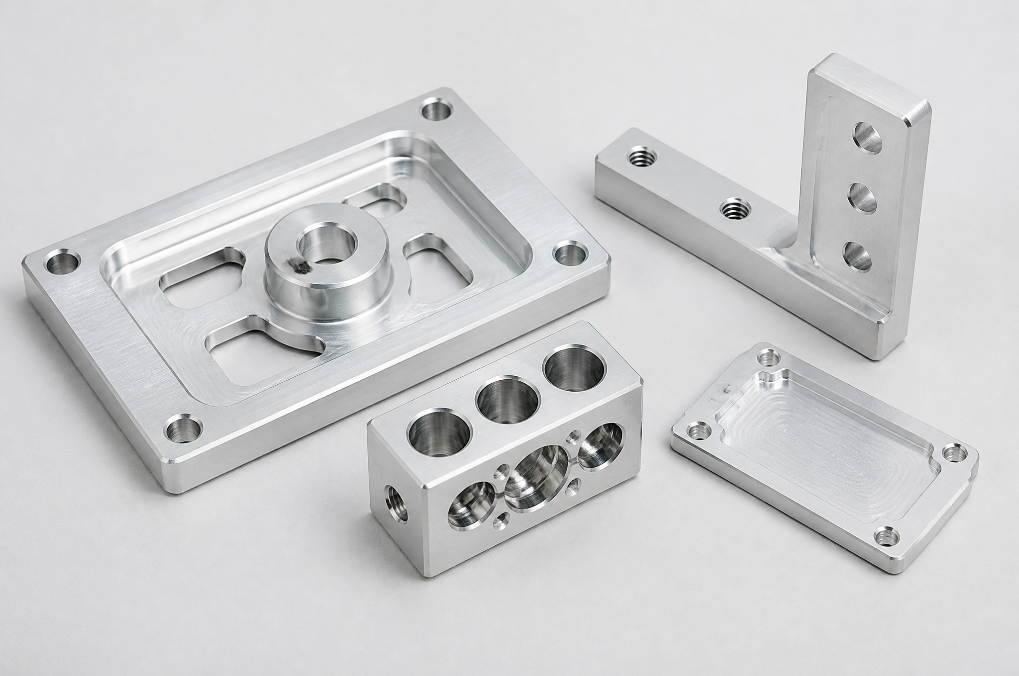
Milled components
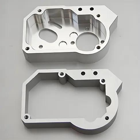
Prismatic parts: housings, plates, brackets, manifolds, covers. Features are pockets, slots, bolt patterns, tapped holes and open contours, cut from one direction where possible. The difficulty is almost never the outline — it is pocket depth against tool reach, and thin floors or walls that move when the part is unclamped.
Turned components
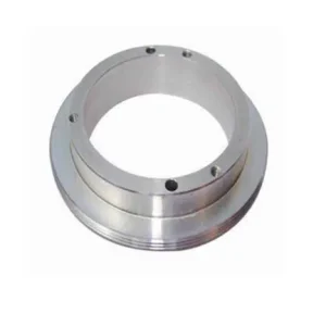
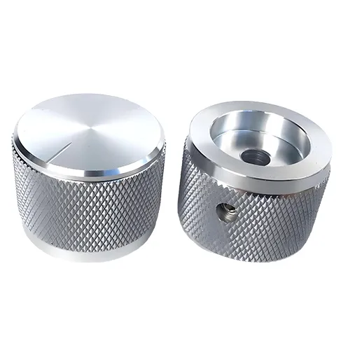
Rotationally symmetric parts: shafts, bushings, sleeves, spacers, threaded fittings, flanged pins. Features are diameters, grooves, threads, bores, chamfers and faces. The difficulty is diameter-to-length ratio, surface finish on a long unsupported section, and any feature that is not coaxial — a flat, a cross hole or a slot on a diameter turns the job into a second operation.
Multi-axis components
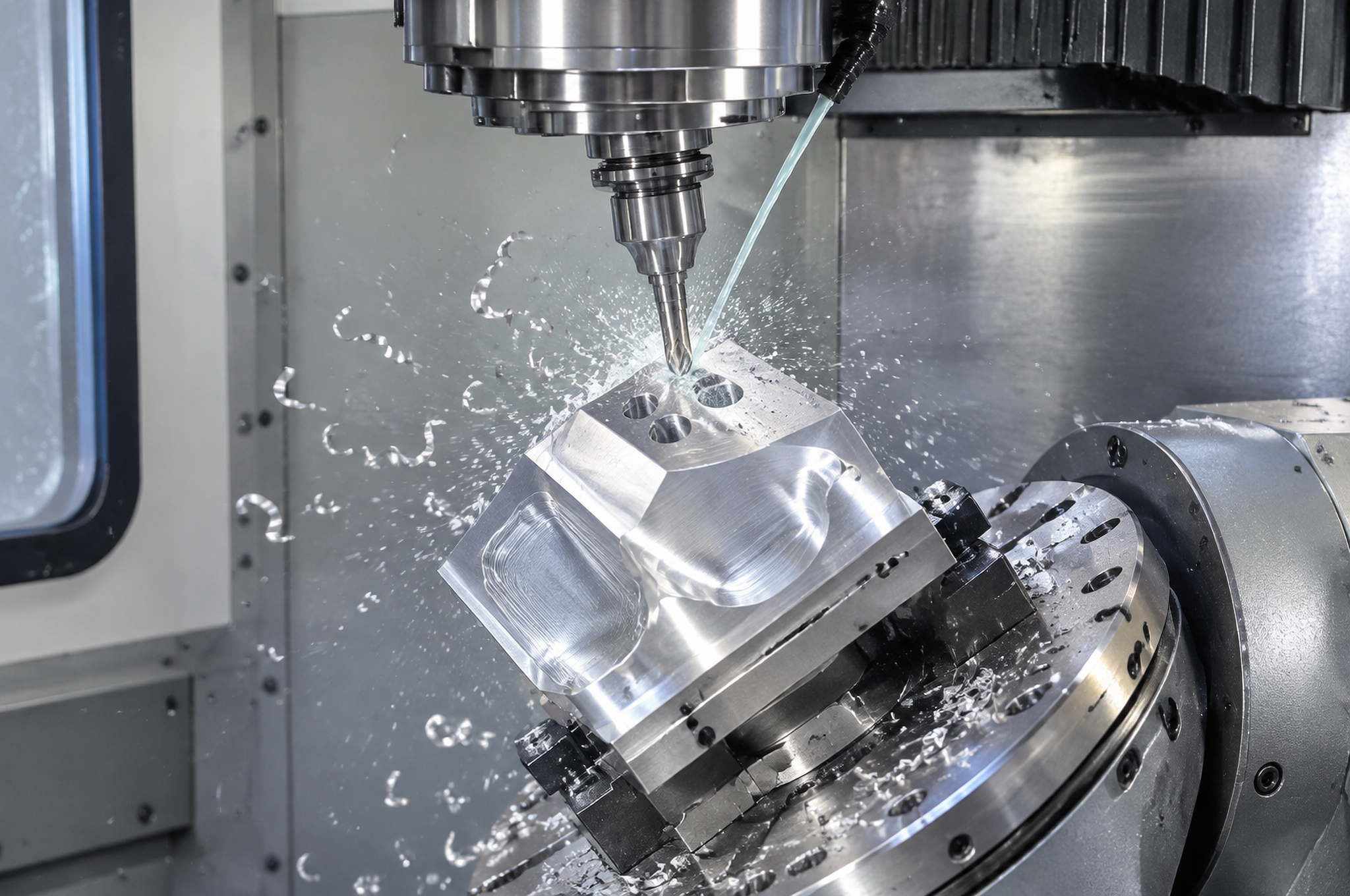
Parts with features on several faces, on inclined pads, or on a curved surface: angled ports, compound-angle holes, contoured bodies, impeller-like forms. The point of a fourth or fifth axis is not prestige — it is that the features keep their relationship to each other because they are cut without being released and re-clamped.
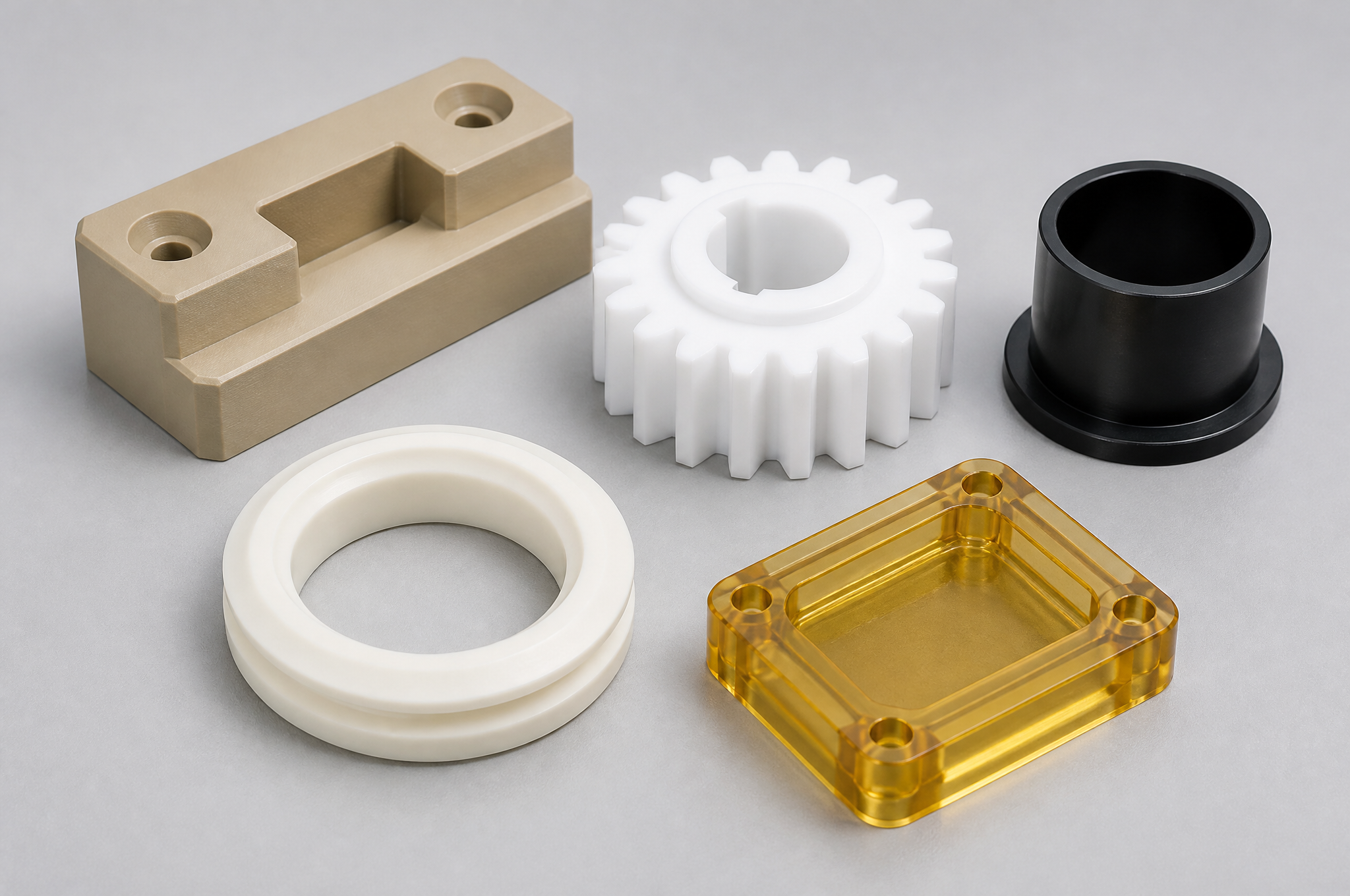
Engineering plastic components
Insulators, gears, bushings, seals, wear pads, fluid-handling blocks. Cutting is easy; holding is not. Plastics move after machining, absorb moisture, build internal stress when a skin is removed from one side only, and burr differently from metal — so the process has to be planned around the material's behaviour rather than around the cutter.
| Feature in your design | What it makes the part | What it costs you |
|---|---|---|
| All features reachable from one face | A single-setup milled part | Nothing extra — this is the cheapest geometry there is |
| Features on two opposite faces | A two-operation milled part | A second datum to establish, and a position error between the faces that no single feature's tolerance describes |
| An inclined pad with holes | A 3+2 or 5-axis part | Either a fixture on an angle or a machine that tilts; the fixture is cheaper once, the machine is cheaper at volume |
| A hole on a curved surface | Multi-axis, or a drilled flat spot | The drill walks on a curved entry unless the surface is spotted first, and the exit breaks out unevenly |
| A cross hole in a turned part | A turn-mill part | A second operation, or a machine with live tooling; either way the position is now a two-axis relationship |
| A flat or slot on a diameter | A milled feature on a turned part | Orientation becomes a controlled dimension, and it has to be measured against the diameter, not the end face |

Which Route a Geometry Actually Needs
Buyers often ask for five-axis machining because they assume it is better. It is better only when the part has a feature that cannot be reached, or cannot stay in relationship, from a fixed three-axis setup. On a part where every feature is reachable from one face, five axes add nothing and cost more per hour. The table is the decision we actually apply at review.
| Route | Trigger in the geometry | What it protects | When it is the wrong choice |
|---|---|---|---|
| 3-axis milling | Every feature reachable from the top face; depth within tool reach | Cost and lead time; one setup, one datum | The moment a feature moves to a second face, the setup count — and the error — doubles |
| 3-axis, multiple setups | Two or three faces, each simple | Simple geometry at low cost | Features with a mutual relationship across the faces: each face is accurate and the pair is not |
| 4-axis, indexed | Cylindrical or wrapped parts with features at angles around an axis | The angular relationship between features around the axis | When the fifth face also has to be cut: the index is a rotation, not an orientation |
| 3+2 (positioned 5-axis) | Inclined pads, compound-angle holes, a few tilted faces | Machining on an angle without a dedicated angle fixture | When the same setup also needs continuous simultaneous motion — positioned axes cannot follow a surface |
| Simultaneous 5-axis | Curved surfaces, deep contoured pockets, ports on a sculpted body | Surface continuity and a single datum across a curved form | Prismatic parts: the extra capability is paid for and not used |
| Turn-mill | A turned part with a cross hole, flat, slot or off-axis feature | The coaxial features and the off-axis feature in one clamping | Parts with no rotational symmetry at all — that is a milling job |
| EDM / wire EDM | Sharp internal corners, hardened material, thin slots a cutter cannot reach | Geometry a rotating tool cannot produce | As a substitute for a machining operation because of a design corner radius — changing the radius is cheaper |
| Grinding | Hardened parts, tight roundness or finish on a journal | Roundness, finish and size after heat treatment | Soft parts where milling or turning already meets the drawing |
Materials: What Each Grade Does Badly
Material tables usually list what a grade is good at, which is the part a buyer already knows. The useful column is the failure mode — because that is what turns into a rejected batch, a warped plate or a thread that strips on assembly. The grades below are the ones we machine routinely; full grade data sits in the material library.
| Grade | Chosen for | Where it bites | Typical parts |
|---|---|---|---|
| 6061-T6 aluminum | Machinability, corrosion resistance, anodizing response | Strength is modest; it galls against stainless threads and welds poorly after anodizing | Housings, plates, brackets, manifolds |
| 7075-T6 aluminum | Strength and stiffness per gram | Notch sensitive, poorer corrosion resistance, cannot be welded, and hard anodizing reduces fatigue strength | Loaded structural parts, aerospace fittings |
| 6082-T6 aluminum | European drawing convention; good strength with better forming than 7075 | Less common off the shelf, so lead time can be longer than 6061 | Structural parts, machine components |
| 304 stainless | General corrosion resistance, food-adjacent equipment | Work hardens under a dull tool and starts to chatter; not chloride resistant | Shafts, bushings, fittings, housings |
| 316L stainless | Chlorides, chemical exposure, medical and marine environments | Gummier to cut than 304, tends to smear and burr; low carbon grade is softer than people expect | Instrument parts, fluid fittings, marine hardware |
| Ti-6Al-4V | Strength-to-weight with corrosion resistance | Low thermal conductivity keeps heat in the cut, so tool life collapses without high-pressure coolant; springy, so thin walls deflect away from the cutter | Aerospace brackets, medical components |
| Brass C360 | Free machining, conductivity, good threads | Lead content restricts some applications; dezincification in certain waters | Fittings, terminals, small precision parts |
| Carbon steel 1045 | Strength at low cost | Corrodes immediately without a finish; machines well only in a consistent condition, so stock condition has to be stated | Shafts, pins, mechanical parts |
| Engineering plastic | Chosen for | Where it bites | Typical parts |
|---|---|---|---|
| PEEK | Temperature, chemical resistance, dimensional stability at temperature | Expensive per kilogram, so stock size and scrap matter; benefits from an annealing step before finish machining | Insulators, high-temperature bushings, fluid parts |
| POM (acetal) | Dimensional stability, low friction, good machinability | Internal stress in extruded bar releases when a skin is removed, so a thin section can bow hours later | Gears, bushings, wear pads |
| PEI (Ultem) | Heat resistance, electrical insulation, transparency in thin sections | Notch sensitive and brittle; sharp internal corners become cracks under load | Insulating covers, electrical components |
| PTFE | Lowest friction, broad chemical resistance | Cold flows under sustained load, so a press fit relaxes; very soft, so holding it without marking is the machining problem | Seals, rings, insulating parts |
| PA6 / PA66 nylon | Toughness, wear resistance, impact strength | Absorbs moisture and grows; a part machined dry to a tight tolerance may not fit after a week in a humid warehouse | Gears, rollers, mechanical parts |
| ABS | Cost, impact resistance, machinability | Low stiffness and heat resistance; solvent and UV sensitive | Housings, covers, prototypes |
Three material rules that come up on nearly every project. Aluminum plate is not stress free. A part machined from the middle of a thick 6061 plate can bow after the clamps come off, because removing material releases the balance inside the plate; a stress-relieved grade, or a rough-and-finish sequence with a pause between, is cheaper than tightening the flatness call on the drawing. Lock the condition, not just the grade. “6061” does not define a temper, and “1045” does not define whether the bar arrived annealed or normalized. Plastics need to be machined in the condition they will live in. A nylon part dimensioned to a tight tolerance, machined from dry stock and shipped into a humid plant, will be a different size on arrival.
The Feature Budget: Which Call on the Drawing Decides the Price
Every part has one or two features that set its cost, and they are rarely the features the designer worried about. This table is the one we use to explain a quotation, because it maps a drawing dimension to the physical reason it is hard — and to the cheapest honest way to make it easier.
| Feature | What makes it hard | Practical limit worth designing to | Cheaper alternative |
|---|---|---|---|
| Thin wall | The wall deflects away from the cutter, then springs back and is cut oversize; clamping closes it before the cut | Wall height to thickness ratio is the number that matters, not thickness alone | Add a rib, reduce wall height, or accept a rougher finish on the non-functional face |
| Deep pocket | Tool reach: a cutter long enough to reach the floor is thin enough to chatter | Pocket depth against cutter diameter, roughly four to five times diameter before it gets expensive | Widen the pocket base, change the corner radius, or accept a stepped floor |
| Sharp internal corner | A rotating cutter leaves its own radius; the corner cannot be sharper than the tool | Corner radius at least equal to a standard cutter radius for the pocket depth | Specify a radius, or move the corner out of the load path |
| Deep or small hole | Drill wander and chip evacuation; length-to-diameter ratio governs both | Beyond roughly five times diameter, hole position and straightness both degrade | Drill from both sides, use a larger diameter, or accept a position tolerance that reflects the depth |
| Thread near an edge | The wall around the thread is thin and the minor diameter is close to the outside face | Engagement length and wall thickness around the thread, not the thread call itself | Move the thread inboard, add a boss, or use an insert |
| Flatness on a thin plate | Release of internal stress and clamping distortion, not the machining | Flatness over the part's longest dimension, referenced to how it is supported | Stress-relieved stock, or a rough-and-finish sequence with a pause |
| Concentricity over a long overhang | Deflection of the workpiece or the tool between supports | Length to diameter of the feature, and whether a steady or tailstock is used | Reduce overhang, add a center, or split the feature into two shorter ones |
| True position on a bolt circle | Every hole is dimensioned from a center that has to be established first | Hole count and circle diameter; more holes at the same tolerance cost more inspection time | Use a positional tolerance with a maximum material condition bonus where the function allows |
| Surface finish on a bore | Reach, tool rigidity and the finish left by the last pass | Ra achievable falls as bore depth and diameter ratio worsen | Specify finish only on the sealing or bearing length, not the whole bore |
Two conclusions follow, and both are worth raising before a drawing is released. First, tolerance is not free but it is not the main cost either — the number of setups, the number of features and the amount of material removed usually dominate. Second, the cheapest drawing change is almost always a radius, a wall thickness or a hole position, and the most expensive is a flatness or concentricity call added “to be safe” on a feature that carries no load.
Tolerance: A Number per Feature, Not a Number per Shop
The most misleading thing on a machining website is a headline tolerance. “±0.005 mm” printed on a page, without saying which features on which material at which size, is a promise nobody can keep across a catalogue — and a buyer who plans around it will eventually be disappointed by a part that was made correctly. We publish the capability, then we qualify it in the same breath.
| What the drawing specifies | How it is normally stated | What makes it achievable |
|---|---|---|
| Linear dimensions | General tolerance block, plus individual calls on critical lengths | Datum scheme and whether the dimension crosses a setup |
| Hole diameter and position | Diameter with a limit, position as true position from stated datums | Boring or reaming after drilling, and cutting related holes in one setup |
| Threaded features | Thread standard and class, depth, and the face it starts from | Whether the thread is cut or formed, and the wall around it |
| Flatness | On a named datum face, with the support condition understood | Stress-relieved stock, sequence, and how the part is rested when measured |
| Parallelism / perpendicularity | Relative to a datum that is actually machined | Cutting both faces in one setup, or measuring the relationship rather than the faces |
| Concentricity / runout | On rotating features, referenced to an axis | Turning between centers, or a single clamping |
| Surface roughness | Ra on named surfaces only | Finishing pass, tool condition, and access to the surface |
| GD&T profile | Profile of a surface against a full datum reference frame | Simultaneous multi-axis cutting, and a CMM program that reproduces the same frame |
The measurement has its own tolerance, and it is not the part tolerance. A CMM in a temperature-controlled room can resolve far finer than most parts need, and that capability says nothing about what a milling machine can hold on a thin wall. The two numbers to keep separate are the instrument's uncertainty and the process capability on that feature; a report that shows a dimension at the edge of tolerance is telling you about the process, not about the CMM.
There is also a geometric trap worth knowing about, because it changes how a tolerance should be written. A position tolerance quoted as a diameter defines a circular zone; a tolerance quoted as plus-or-minus defines a square one. The square's corners lie outside the circle, so a part can pass a ±0.05 reading and still fail a Ø0.1 position requirement. If the function is “the pin must pass”, specify the circular zone and let the machinist and the inspector work to the same shape.
What a Design Review Actually Changes
Design for manufacturability is often sold as a checklist. In practice it is a short list of decisions that change the route, the price or the risk, and it is only useful if it happens before the program is written. These are the eight we raise, in the order they matter.
| Check | What we look for | What we propose |
|---|---|---|
| Datum scheme | Whether the drawing's datums are machinable faces, or whether they are theoretical | A datum that exists after the first operation, and a callout that follows it |
| Setup count | Features that force a second or third clamping | Reorient the part, or accept a 4th-axis index, so related features are cut together |
| Wall and floor thickness | Ratio of wall height to thickness; floor under a deep pocket | A rib, a shallower pocket, or a rough-and-finish sequence with a stress-relief pause |
| Tool access | Pocket depth against cutter diameter; corner radii smaller than a standard cutter | A larger corner radius, a wider pocket base, or a stepped floor |
| Hole design | Length-to-diameter, breakout on a curved surface, holes breaking into each other | Spot-face the entry, drill from both ends, or accept a realistic position tolerance |
| Threads and inserts | Thread depth against hole depth; wall thickness around a thread | Deeper engagement without a through wall, or a threaded insert where the substrate is soft |
| Material condition | Whether the grade, temper, form (plate, bar, extrusion) and stress state are stated | A specific condition, and stress-relieved stock where flatness matters |
| Finish compatibility | Whether the specified finish suits the substrate, and what it does to dimensions | An alternative finish, or a pre-finish allowance on features that must stay in tolerance |
Surface Finish, Chosen Against the Substrate
Finish is where a machining quotation most often changes after the fact, because the finish a buyer names is sometimes incompatible with the material, or changes a dimension that was toleranced before it was chosen.
| Substrate | Finishes normally applied | What it does to the part | What to watch |
|---|---|---|---|
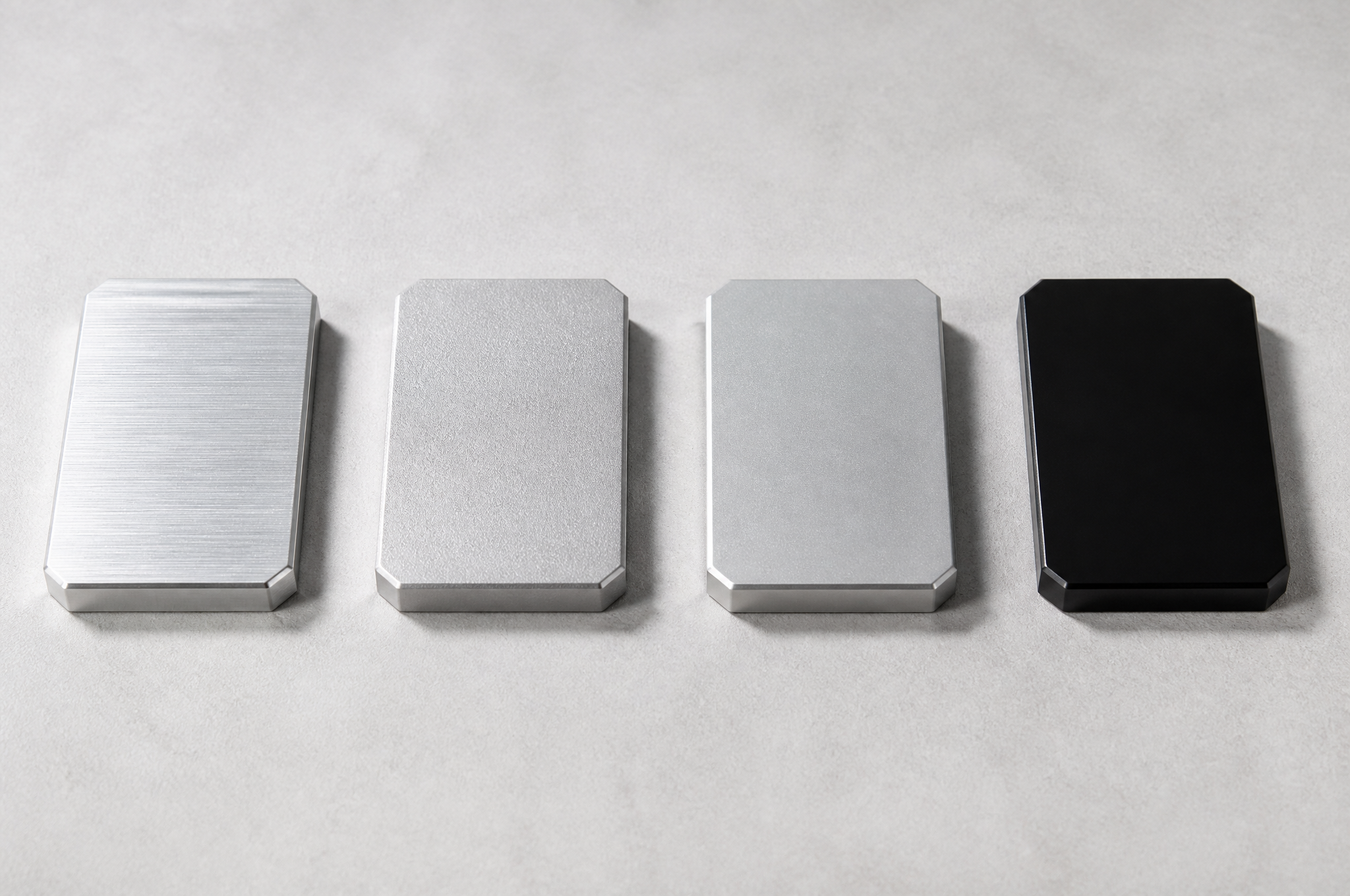
| Aluminum | As-machined, bead blasting, Type II anodize, Type III hard anodize, chromate conversion, powder coat | Anodize adds 10–25 µm per surface (Type II) or 25–50 µm (Type III) and grows both outward and inward, so a bore closes by twice the film | Mask threads and bores that must stay in tolerance; hard anodize reduces fatigue strength on a loaded part |
| Stainless steel | As-machined, bead blasting, passivation, electropolishing, mechanical polishing | Passivation removes free iron and does not move dimensions; electropolishing removes material, so bores grow and edges round | Do not tolerance a bore and then electropolish it without an allowance |
| Carbon steel | As-machined, black oxide, zinc or nickel plating, powder coat | Plating adds a film of a few to tens of micrometers; black oxide barely moves dimensions | Hydrogen embrittlement risk on high-strength plated parts; edges plate differently from faces |
| Brass | As-machined, polishing, plating, bead blasting | Cosmetic improvement; plating builds on threads | Soft substrate marks during handling; specify protection for visible faces |
| Titanium | As-machined, bead blasting, polishing, specified anodizing | Anodizing on titanium is a thin oxide, largely cosmetic and dimensional-neutral at normal thickness | Color is process-dependent; a physical sample is a better reference than a color name |
| Engineering plastics | As-machined, deburring, tumbling, polishing, laser marking where specified | No coating in most cases; finish is a cutting result | Solvent-based cleaners can craze PEI and polycarbonate; a machined finish is the honest spec |
Inspection, and the Documents That Come With It
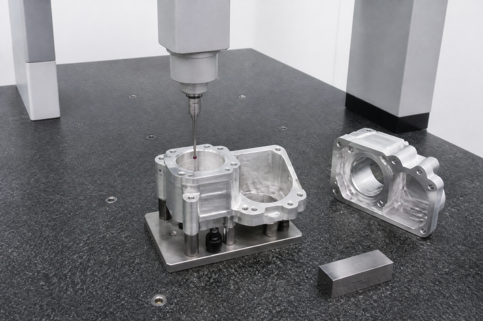
“100% inspection” is a sentence that means nothing until it says which characteristics were measured, against which drawing revision, with which instrument. What we can commit to is narrower and more useful: the characteristics that affect fit and function are measured and reported, and the document set is agreed at quotation rather than discovered at shipment.
| Document | What it proves | What it does not prove |
|---|---|---|
| Material certificate | The grade and heat number of the stock that went into the part | That the finished part meets the drawing — a correct material can still be machined wrong |
| Dimensional inspection report | The measured values of the characteristics in the agreed plan | Anything outside that plan, and anything not measurable with the method used |
| CMM report | Position, form and orientation against a stated datum frame | A capability claim on a feature the CMM was not programd for |
| First article inspection (FAI) | That the first part of a run was verified against the drawing in full | That every subsequent part is identical — that is process control, not FAI |
| Surface roughness record | Ra on the surfaces that were measured | Finish on a surface the instrument could not reach |
| Visual / cosmetic record | That the agreed cosmetic criteria were checked | Subjective acceptance criteria that were never written down |
Two standard numbers cause more confusion than any other on a purchase order, and neither is a machining certification. AS9102 is the aerospace standard for the format and content of a first article inspection report: it tells you how an FAI is documented, not that a shop is approved to make aerospace parts. EN 10204 3.1 is a type of material inspection certificate, issued by the mill or by the stockholder with traceability to the heat: it describes a document, not a product certification. Our quality management system is certified to ISO 9001:2015; anything beyond that is agreed per project and, where a customer's industry requires a certified special process, resolved at supplier approval rather than implied on a web page.
One Piece and Ten Thousand: What Actually Changes
Buyers often ask for a prototype price and a production price in the same enquiry, then find the two numbers hard to compare. They are different products, because the work behind them is different. Below is what changes at each stage — and, importantly, what does not.
| Stage | What the buyer needs from it | What we do differently | What does not change |
|---|---|---|---|
| Single prototype | To prove the design and hold it in their hand | Program and setup spread over one part; stock may be cut from plate or bar rather than ordered to size | The drawing review — a prototype made to a weak drawing proves the wrong thing |
| Engineering validation | To test function, fit and life | Material condition and finish become fixed, because a finish can change a fit | Datum scheme and critical features |
| Low-volume production | A first batch for a customer build | Fixture and soft jaws justified; first article inspected and reported | The measurement plan |
| Pilot production | To prove the process before committing tooling | Process frozen, in-process checks added, stock size and supplier settled | Program and fixture, which now have to be controlled documents |
| Repeat production | Consistency across orders | Program, fixture and inspection plan held against the drawing revision; changes to any of them treated as a change | The revision the part is made to — unless the customer issues a new one |
What makes a part cheaper at volume is not the machine getting faster. It is that the setup, the program, the fixture and the first-article inspection are paid for once instead of per piece, and that stock can be ordered in the right size instead of cut from a larger one. What makes it dearer at volume, unexpectedly, is a drawing that was never frozen: a revision that arrives mid-run invalidates the program, the fixture and the inspection plan together.
What the Drawing Has to Carry, and How Confidentiality Is Handled
A 3D model defines the shape; it does not define what is acceptable. The drawing does that, and a drawing that omits the items below will always be resolved by somebody's assumption — usually the shop's, which is the wrong party to be deciding it.
| Item | Why it is not optional |
|---|---|
| Revision and part number | The only way a shop and a customer can be sure they are discussing the same geometry |
| Datum reference frame | Position, orientation and form are all meaningless without it, and the CMM alignment depends on it |
| General tolerance block | Without it, every untoleranced dimension becomes a negotiation |
| Critical characteristics flagged | So the inspection plan can be built around the two or three features that actually decide acceptance |
| Material grade, temper and form | Plate, bar and extrusion behave differently; temper decides strength and machinability |
| Finish, and the surfaces it applies to | A finish named without a scope will be applied to threads it should not touch, or skipped on an interior face |
| Quantity and expected repeat | Decides fixture investment and stock strategy, which is most of the price difference between one and a thousand |
| Thread standard and class | “M6” is not a specification; the class and depth are |
On confidentiality: drawings arrive under whatever arrangement the customer needs. We work under NDA on request, keep files inside the project rather than in open circulation, and treat a drawing revision as a controlled document — the shop floor works from the released revision, not from a photograph of a screen. If your IP process requires a specific handling statement, say so with the enquiry and it becomes part of the quotation rather than a discussion after the order.
Frequently Asked Questions
Can you machine parts directly from a STEP file?
What is the difference between CNC milling and CNC turning for my part?
Which materials can be CNC machined for industrial components?
What tolerances can you achieve on machined parts?
Is 5-axis machining necessary for complex metal components?
Can you produce both a single prototype and a production run of the same part?
What information do you need to quote a CNC machining project accurately?
How are machined parts inspected before shipment?
What is the difference between a material certificate, EN 10204 3.1 and AS9102?
Which surface finishes are available for aluminum and stainless steel parts?
How can I reduce the cost of a CNC machined part?
How are customer drawings and intellectual property handled?
Send the Drawing, the Model and the Revision
STEP or IGES with a dimensioned PDF, the material grade and condition, the quantity you expect, the critical features, the finish and the documents you need. The review comes back with the route we would take, the features that will decide the price, and anything on the drawing that cannot be made or cannot be measured as called — before a program is written.
Upload Your Drawing and Request a QuoteSTEP · IGES · X_T · DXF · DWG · PDF · NDA on request
Related Capability Pages
CNC machining services
The plant, the machine list, the published tolerance tables and the process photography. Machining capability
CNC milling services
Pocketing, profiling, drilling and multi-face work, and how each setup is established. Milling
CNC turning services
Shafts, bushings, threads and bores, including slender work and live-tooled operations. Turning
5-axis machining
Positioned and simultaneous five-axis work for multi-face and contoured components. Five-axis
Aluminum machining
6061, 7075 and 6082 in plate, bar and extrusion, with anodizing and hard anodizing. Aluminum parts
Titanium machining
Ti-6Al-4V components where heat, tool life and deflection set the process. Titanium parts
Surface finishing
Anodizing, passivation, plating, blasting and polishing, with the dimensional effect of each. Finishing
Quality and certifications
What the quality system covers, which documents are issued, and what is not claimed. Quality
Prototype to production
How a part moves from a first-off sample to a controlled repeat process. Prototype to production